Another CNC Machine waiting to be designed and made?
I noticed a post on “Ships of Scale” in which a ship modeler had made a prototype of a simple small rolling mill for bending wooden model ship’s planks. His innovation was to coat the metal rollers with rubber, which increased the grip on the planks and reduced the possibility of marring them.
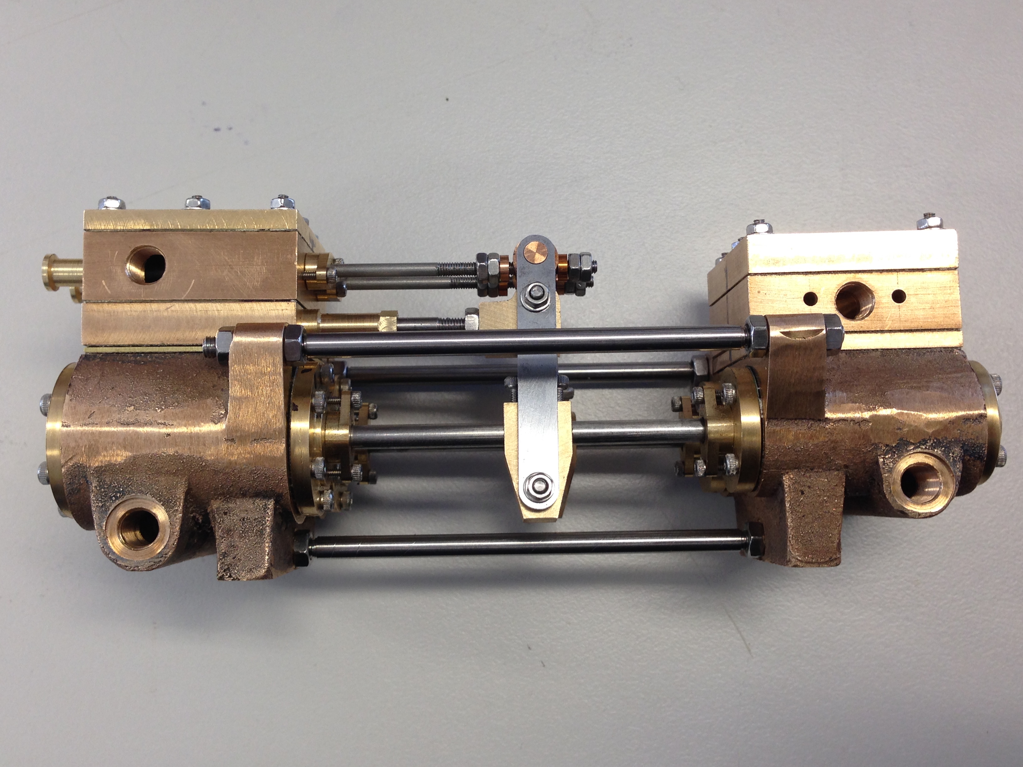
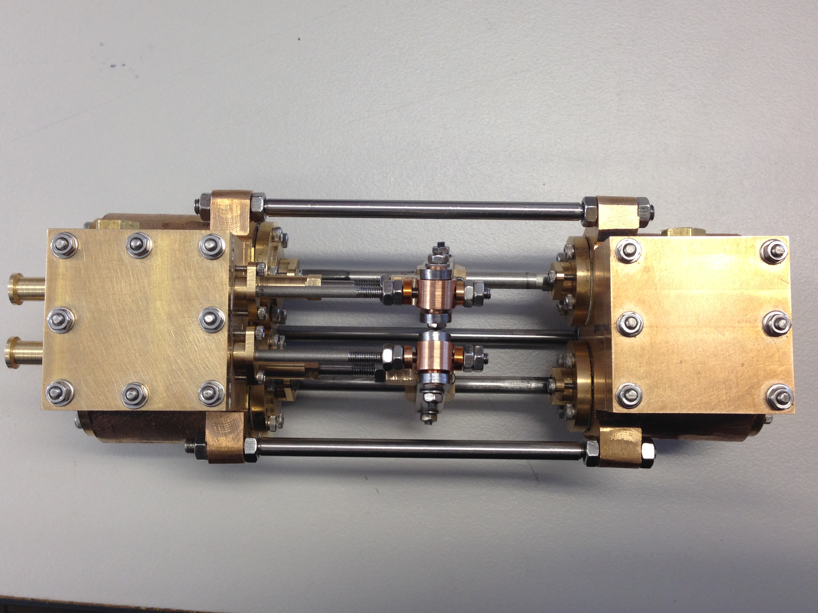
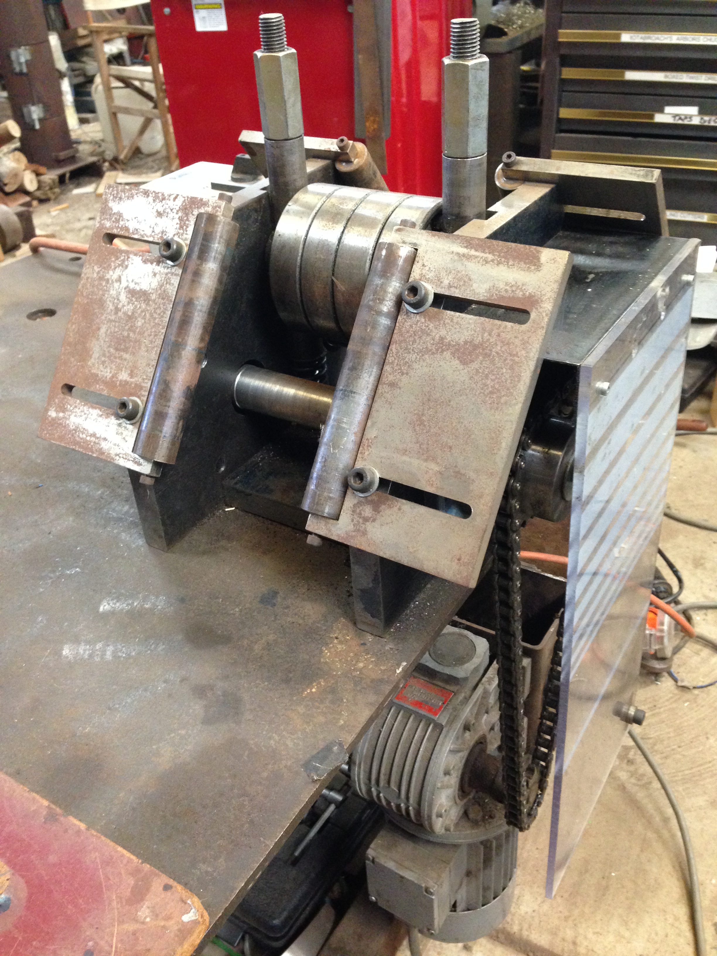
Some years ago I made a rolling machine for putting curves into steel bar up to 13mm thick and 100mm wide. It is electrically powered and reversible, and has been used on many occasions, including some where it was used to its physical limits. https://johnsmachines.com/2018/05/23/home-made-ring-roller-and-first-attempts-at-bronze-brazing/
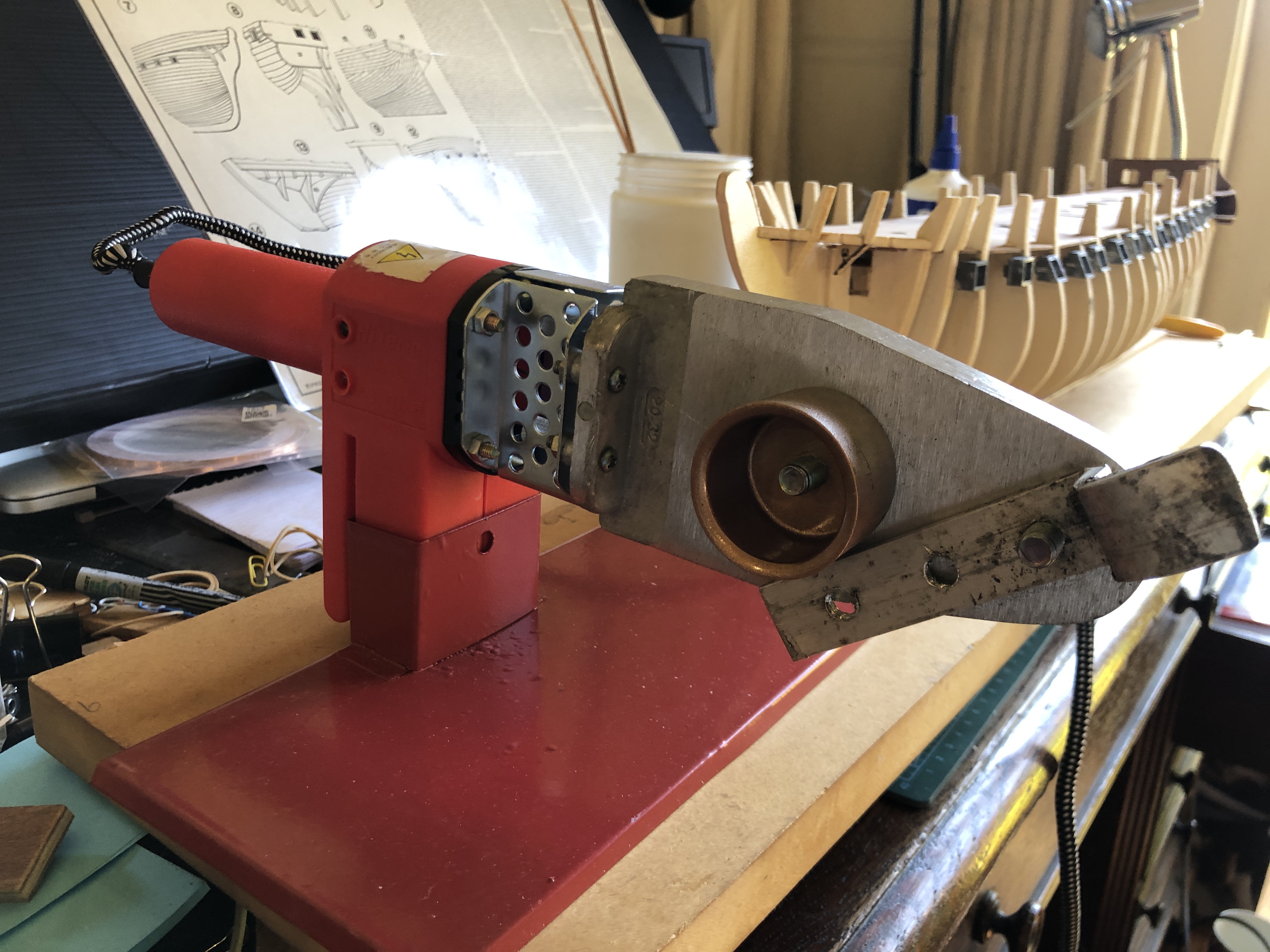
With that experience behind me, I started thinking about how I would approach the issue of bending strips of wood 0.5 – 1mm thick, and typically 5mm wide, an up to 1 meter long. I had previously also adapted a PVC welding machine to the same end, but the idea of a rolling machine has appeal.
It would have 3 rollers, probably with a compressible surface like rubber or plastic. All rollers would be driven so there would be no slippage. And it would be electrically driven, reversible, and small. The rollers would probably be only 10mm diameter and maybe 25mm long.
Then a further thought….
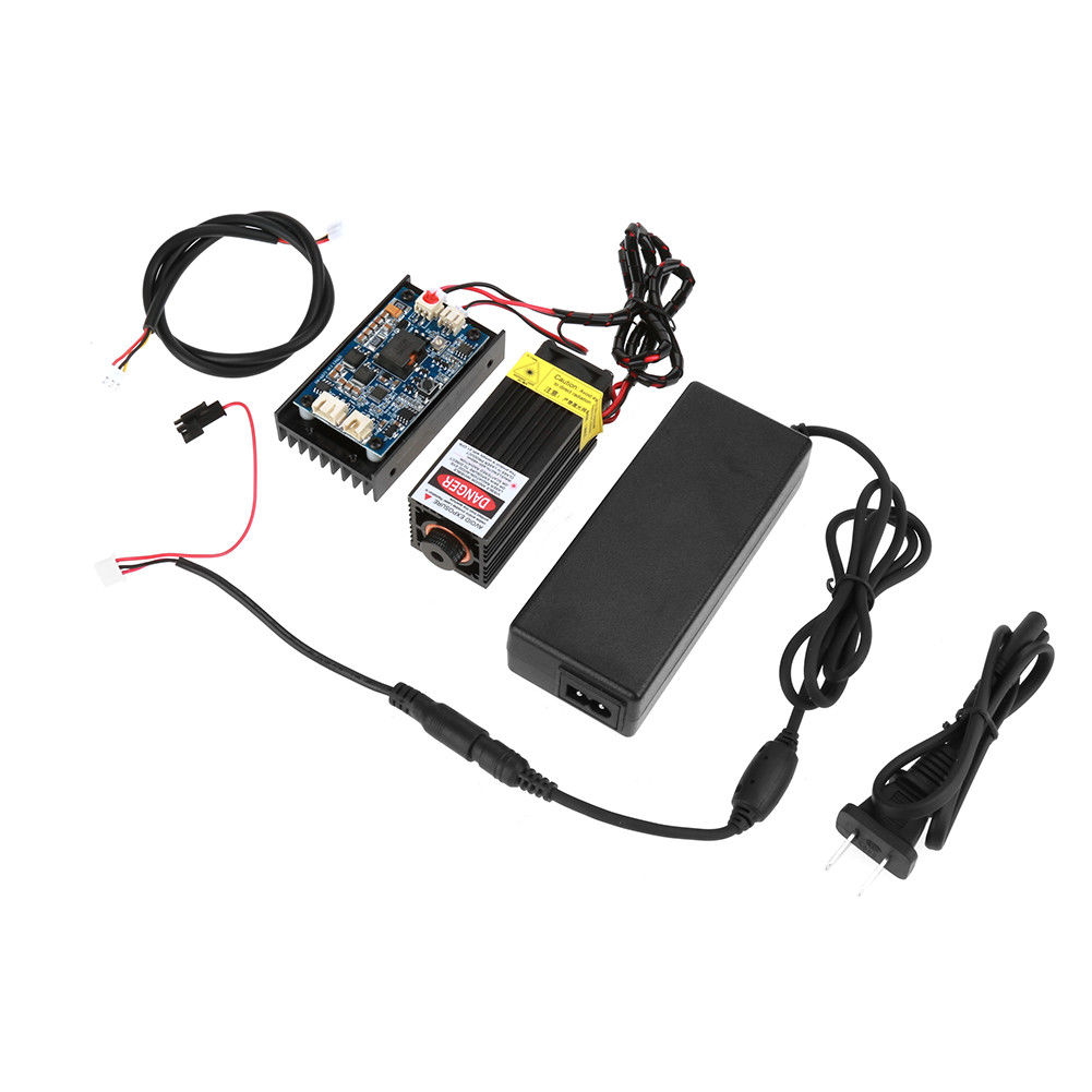
Why not make it CNC controlled, and using small, cheap, controllable Nema 17 motors, or smaller?
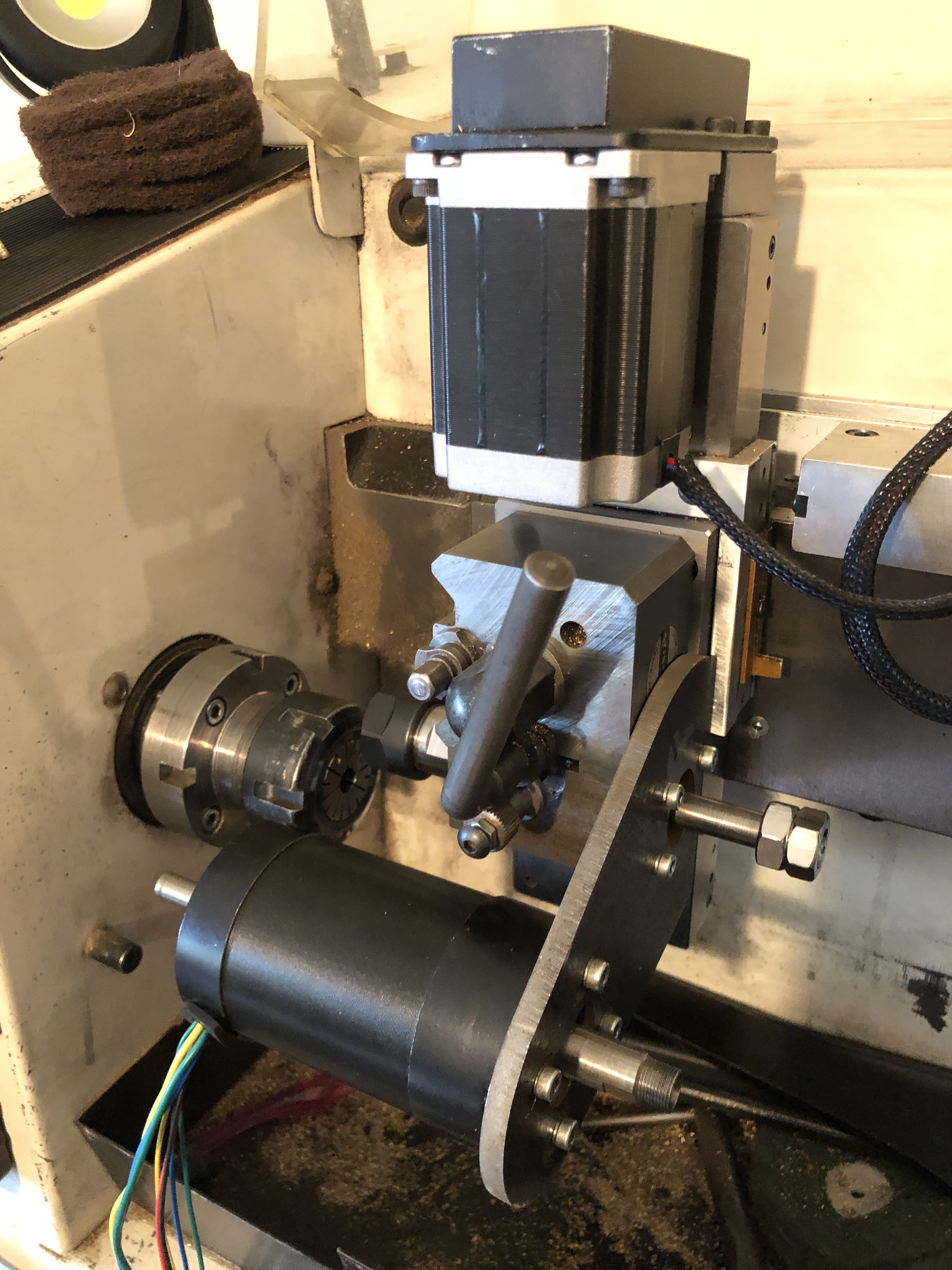
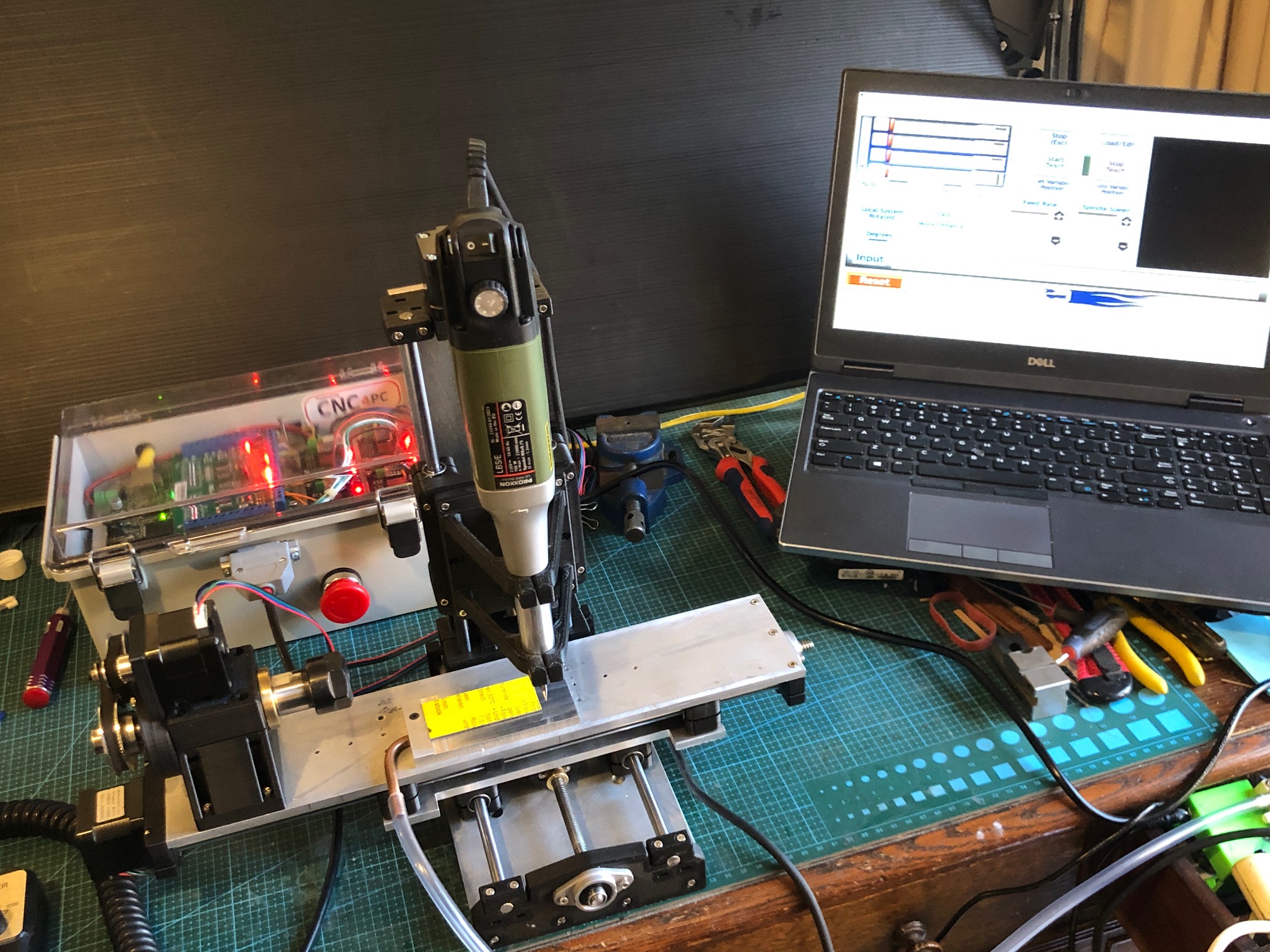
The CNC controller already exists, being used for my tiny CNC mill and CNC seizing/serving machines. The controller was the most expensive part of those machines. Why not use it with small stepper motors to control the speed of pushing the strips of wood through the machine, the direction of the passage, the radius of the bend in the wood, the number of passe?. AND varying the radius of the bend along the length of of the planks!!
It would require a stepper motor to drive the 2 lower rollers, and another stepper motor to drive the top roller in the reverse rotation. And a third stepper to change the degree of separation of the top and bottom rollers, thus varying the radius of the bend.
There would need to be some new programming of G codes. But I reckon that it would do the job, more quickly, smoothly and repeatedly and controllably than any other existing method.
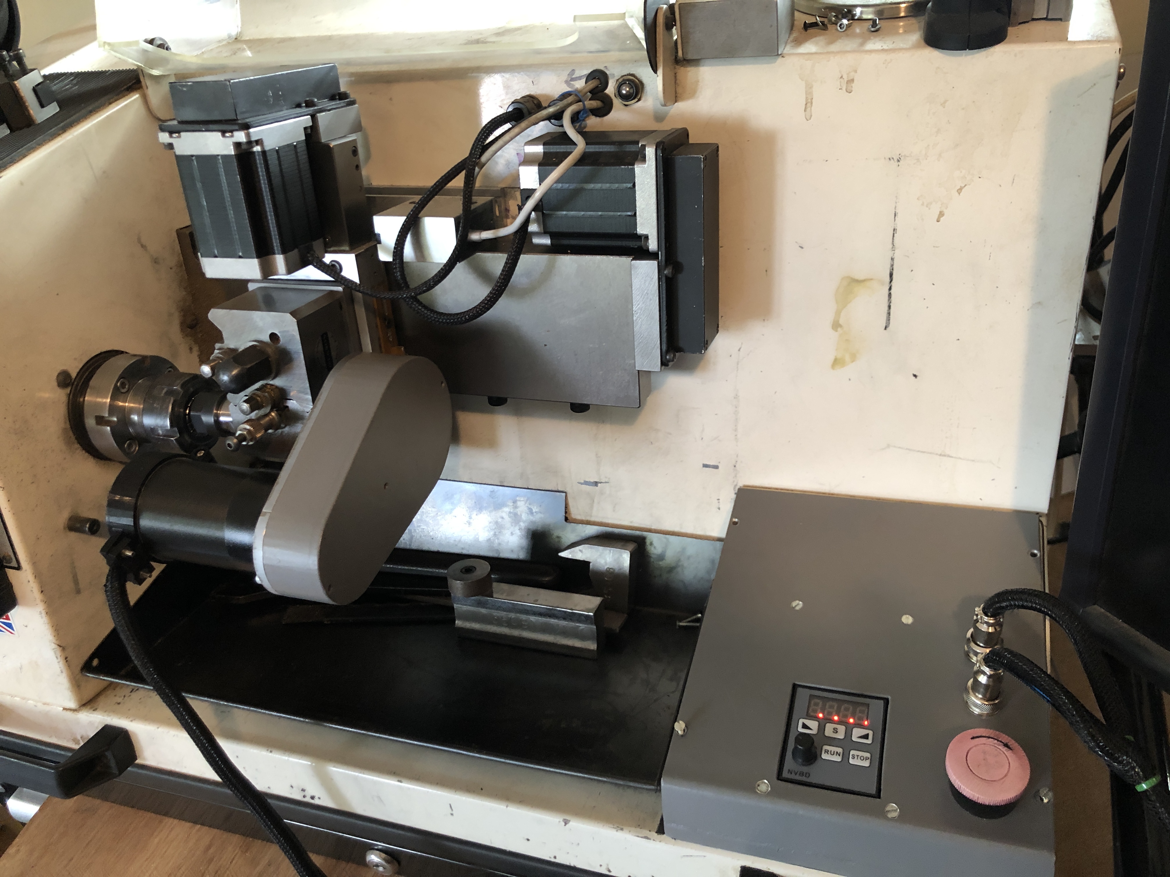
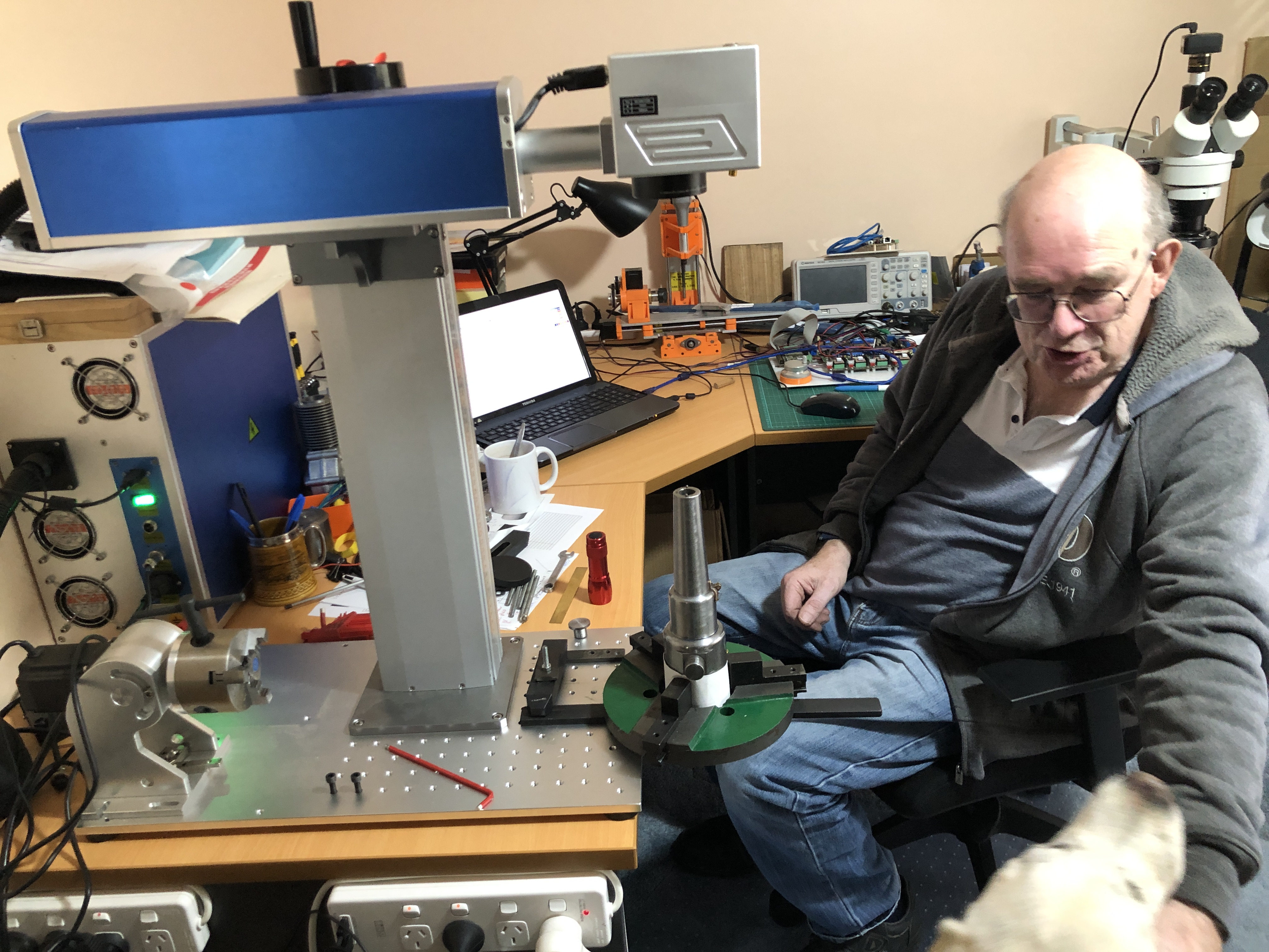
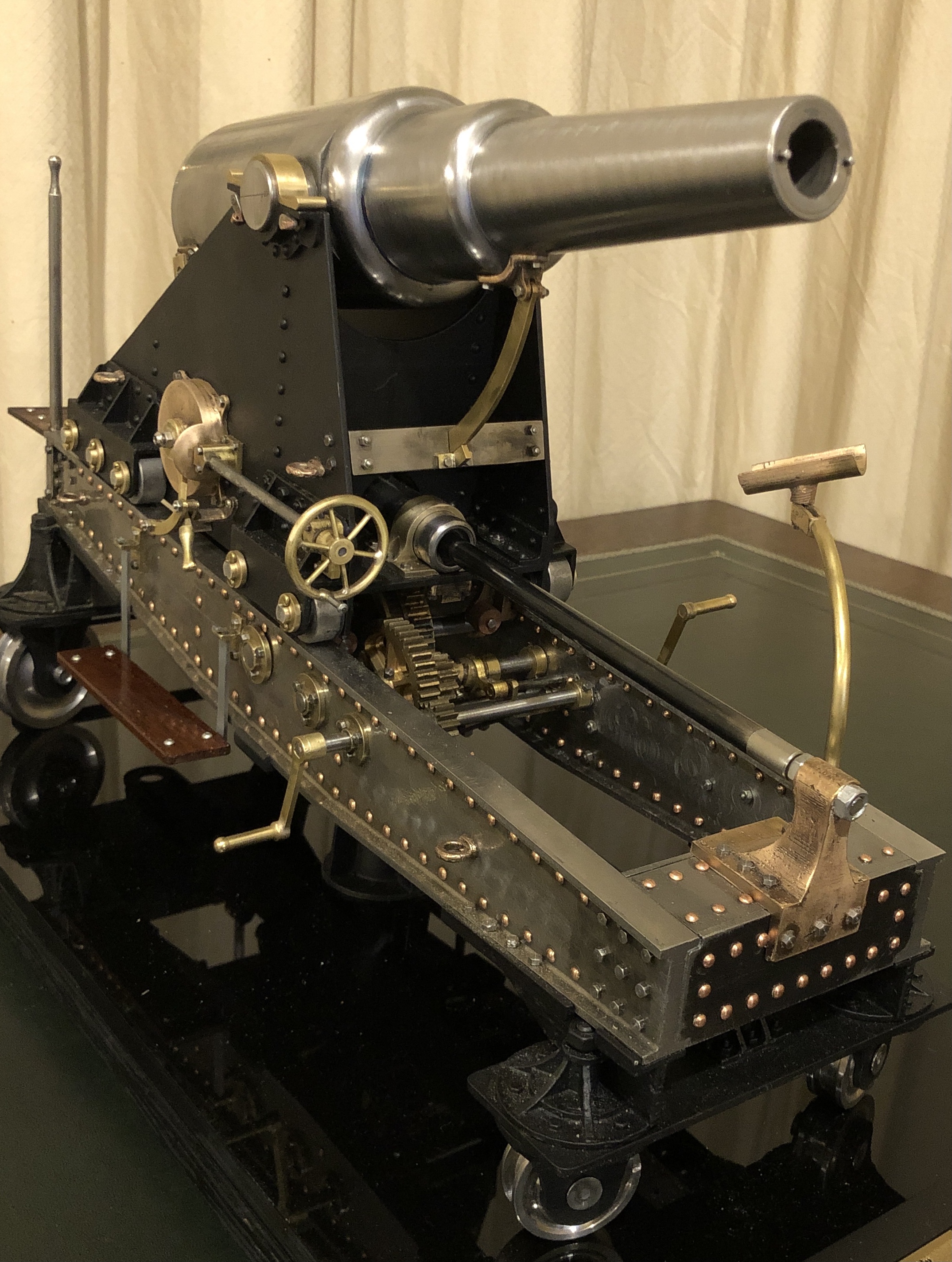
It would be a small machine, not very complicated. Maybe as complex as the seizing serving machine, but simpler than the 4 axis CNC mill pictured above.
The wood strips would be presoaked or microwaved, to make them more pliable. I considered the possibility of heating the rollers, but probably not.
Each pass would slightly increase the degree of bending, minimising the chance of breakage. Each pass could be very rapid, and automatically reversed. Just some fancy G coding required. Maybe a table with spaces to be filled in.

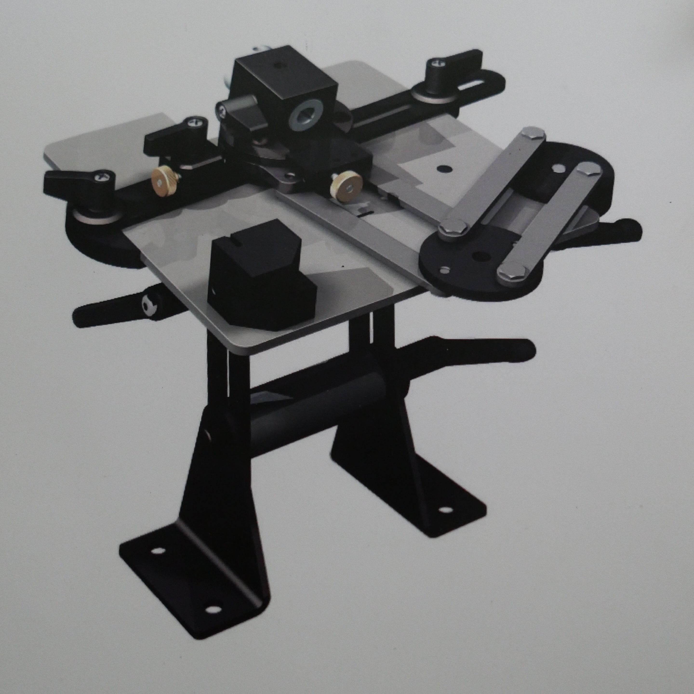
That is just a concept drawing. Already I am thinking that the rollers could be 8mm diameter, plus soft coating (?rubber or plastic), because I have bearings and rods in my workshop stock. Will discuss the idea with my expert friend Stuart.