johnsmachines

machines which I have made, am making, or intend to make, and some other stuff. If you find this site interesting, please leave a comment. I read every comment and respond to most. n.b. There is a list of my first 800 posts in my post of 17 June 2021, titled "800 Posts"

Category: model cannon

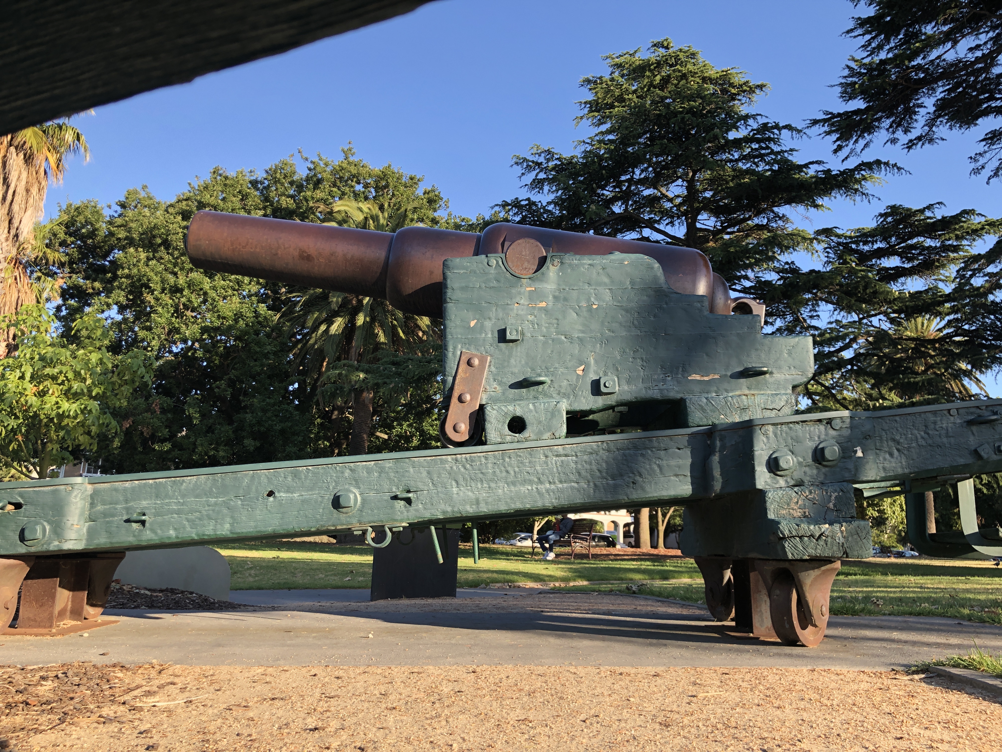
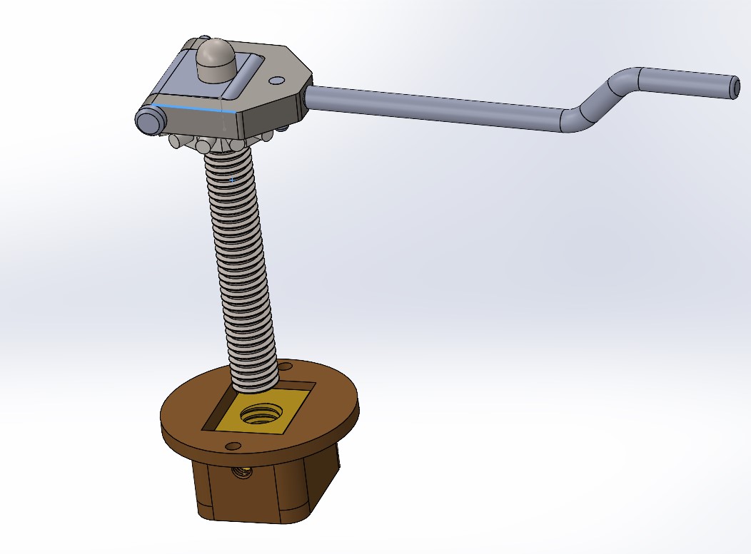
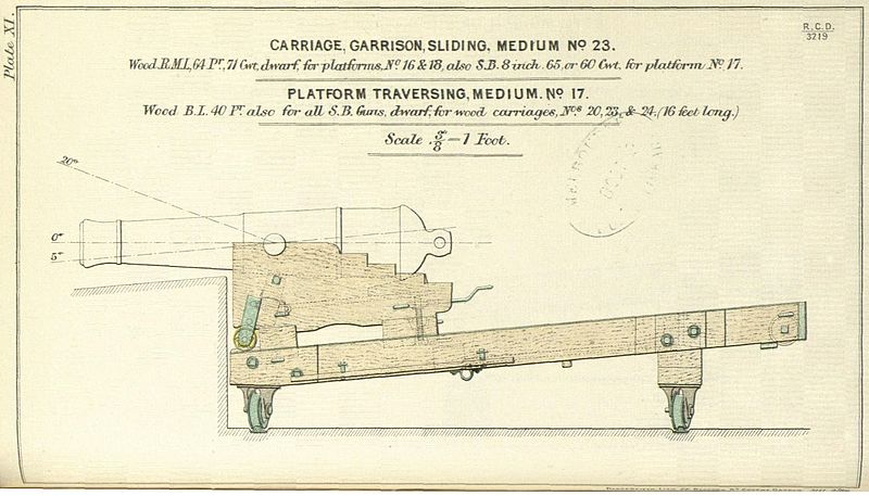
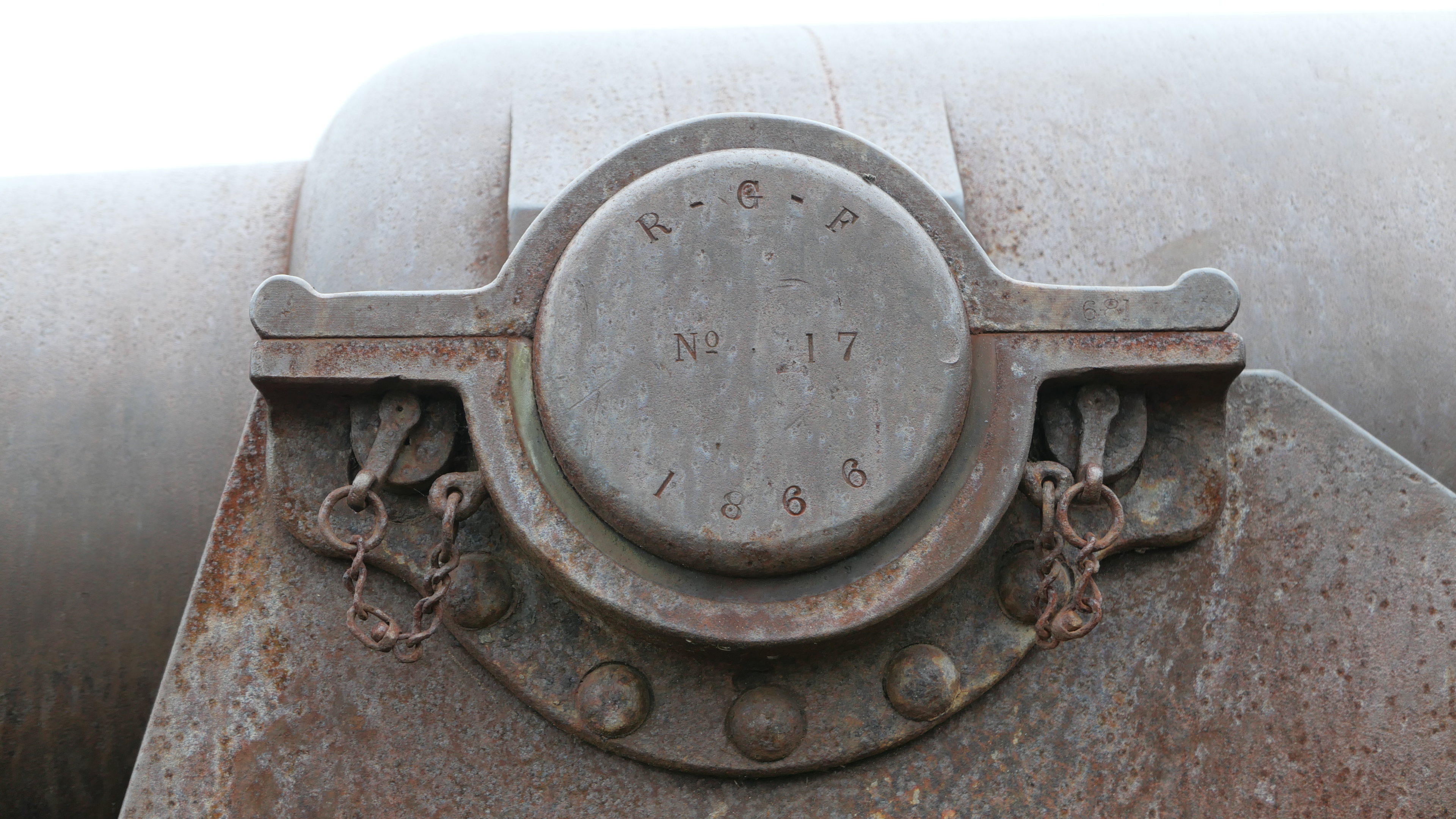
Model Armstrong 110pr Sights

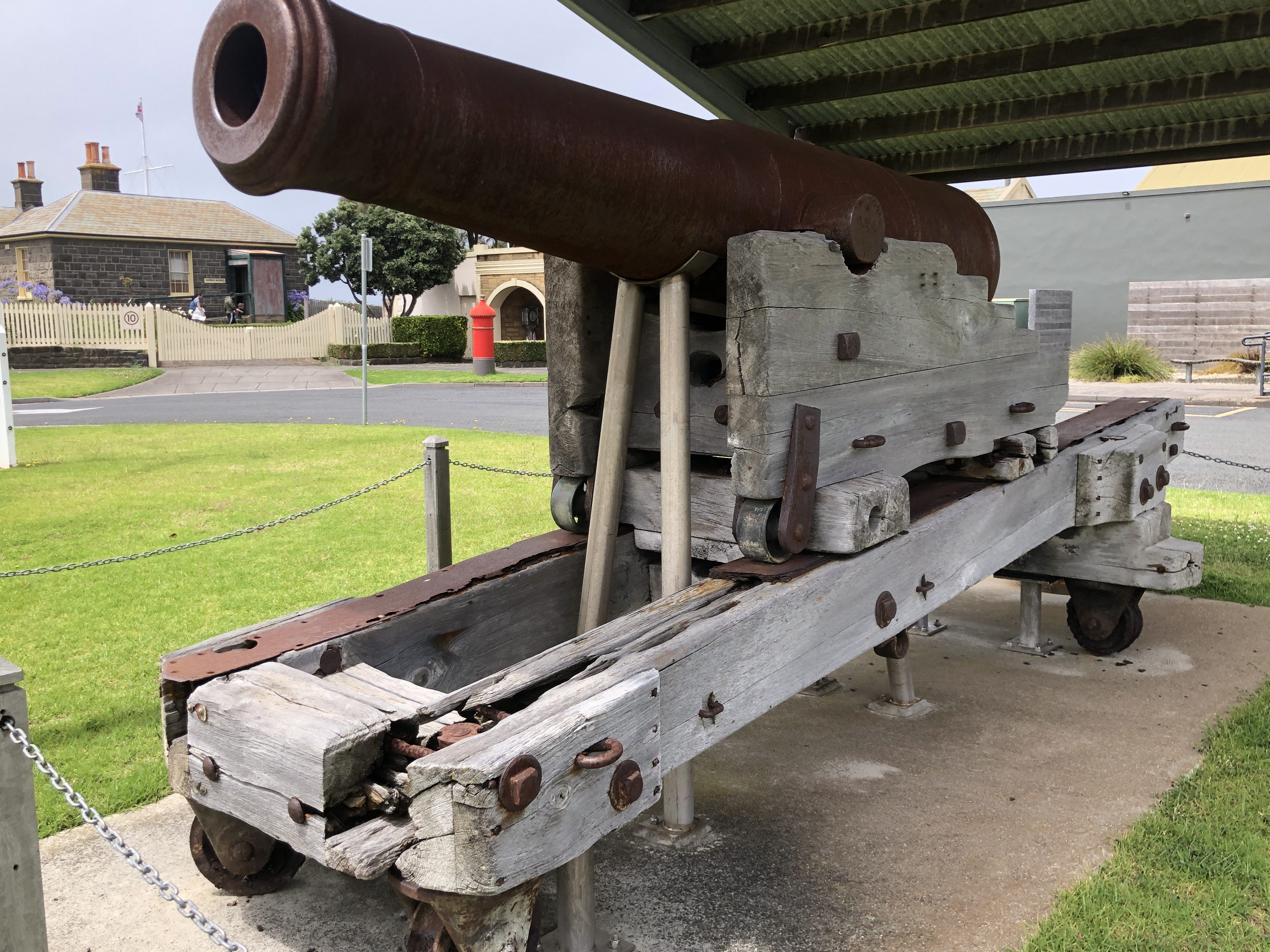
The 1861 Armstrong rifled breech loader cannon had foresights on the trunnion ring, and rear sights on the breech. The foresights had fixed lengths. The rear sights were adjustable and graduated for range. The foresights were vertical. The rear sights were canted at a 2º16″ angle to compensate for slight lateral deflection of the projectile caused by the rifling. The rear sights also had a lateral adjustment screw to compensate for movement of the target.

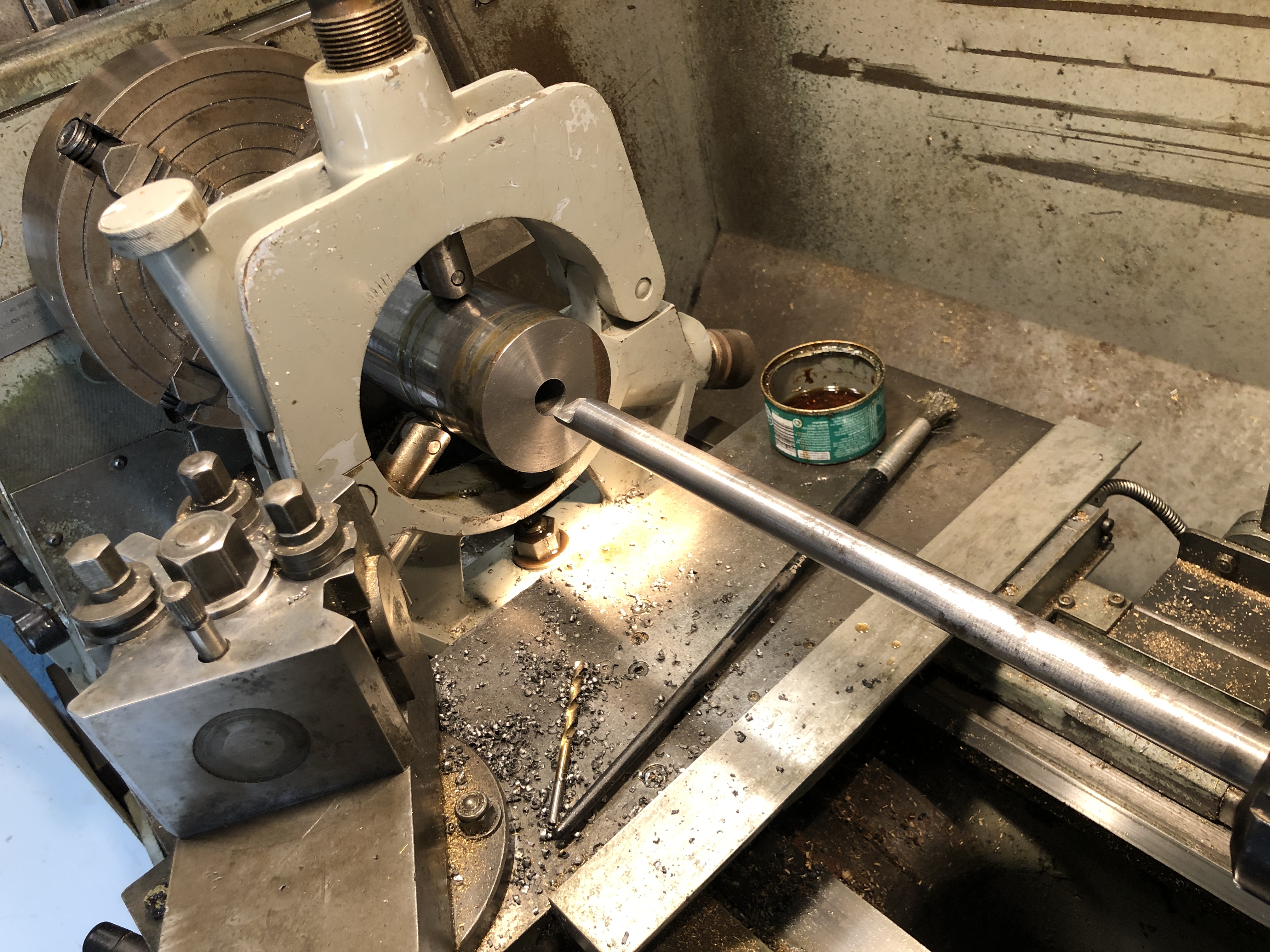
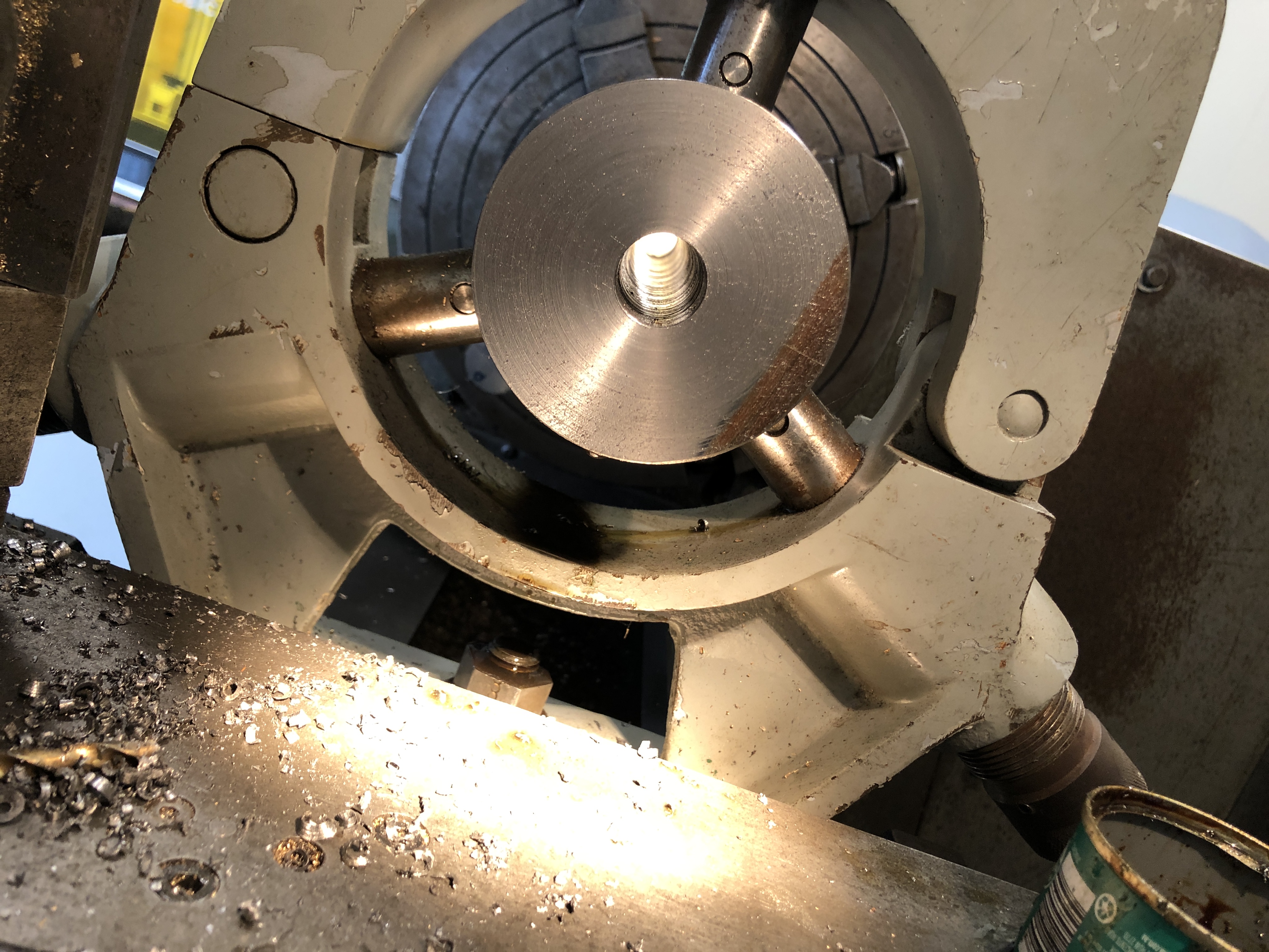
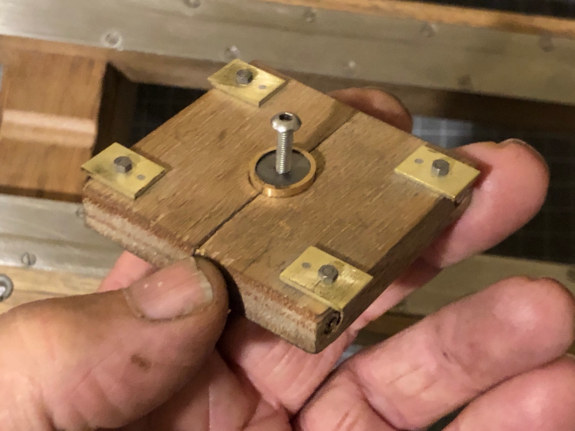
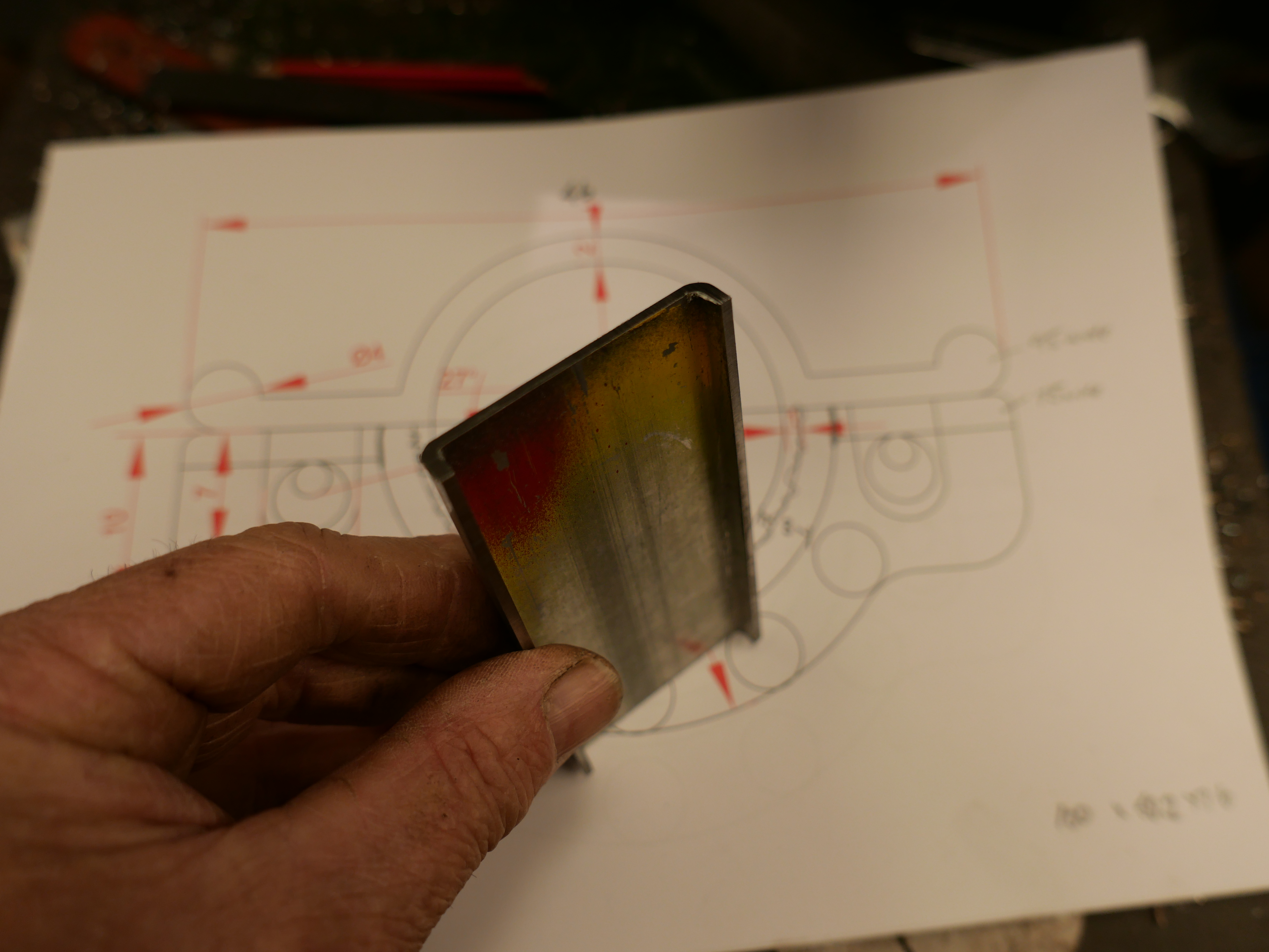
At 1:10 scale, the components of the sights were tiny, and I decided to not make the lateral compensating adjuster. But I did decide to incorporate the 2º angulation. That required the left and right rear sights to NOT be equidistant from the centre line of the barrel. The drilling of the barrel holes for the sight holders was consequently not straightforward, and I spent a couple of hours on the CAD drawing to work out the drilling positions, depths, angles etc. And then considerable time was spent setting up the barrel in the milling machine vise, so that the bore was horizontal, parallel with the mill table, and level when the foresights were drilled, and tilted 2º when the rear sights were drilled.

That took two full machining sessions over two days. I was not looking forward to it, knowing that a broken drill or other mishap would be catastrophic. In the event, it all worked out OK. Some pics…

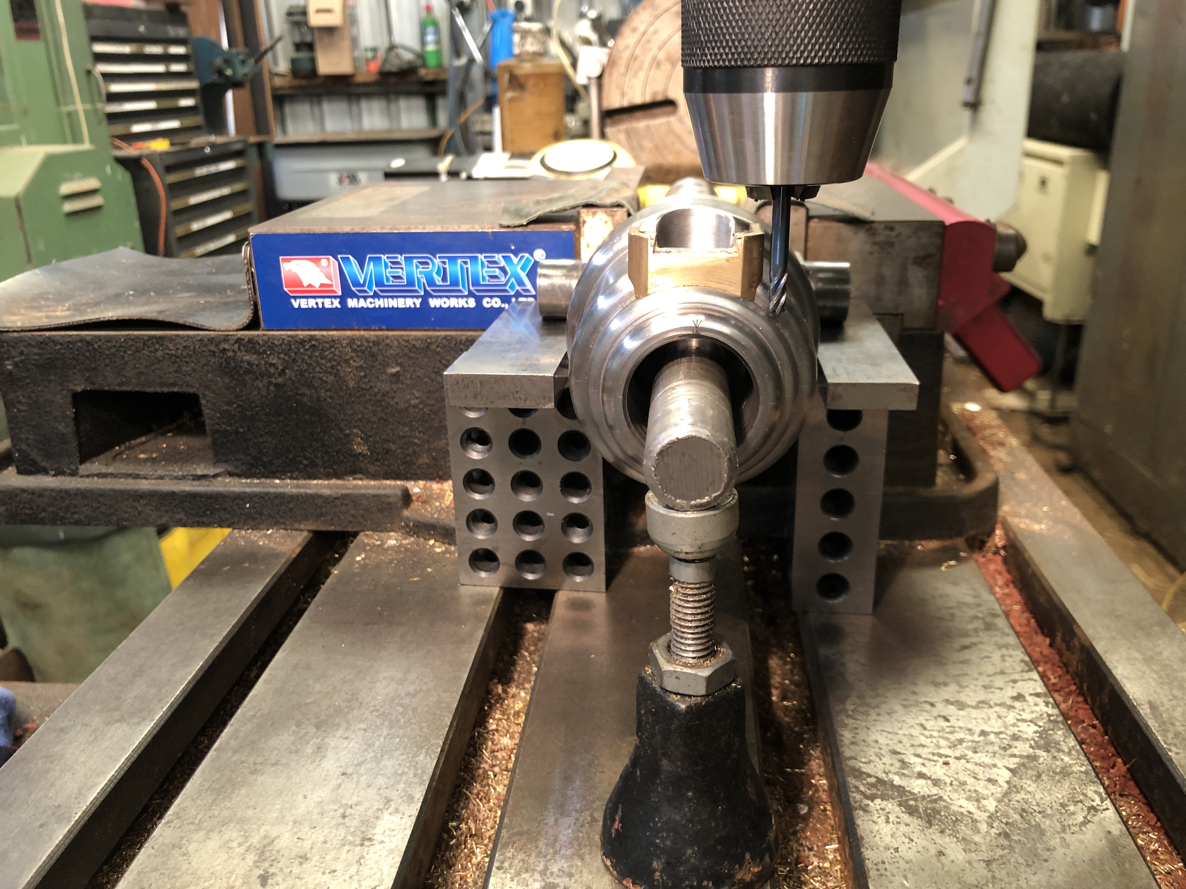
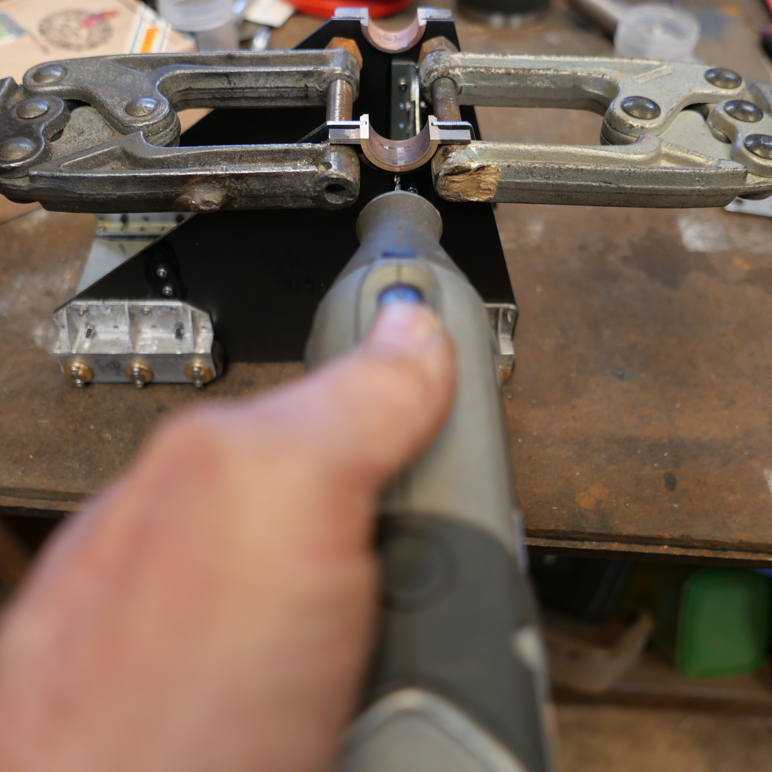
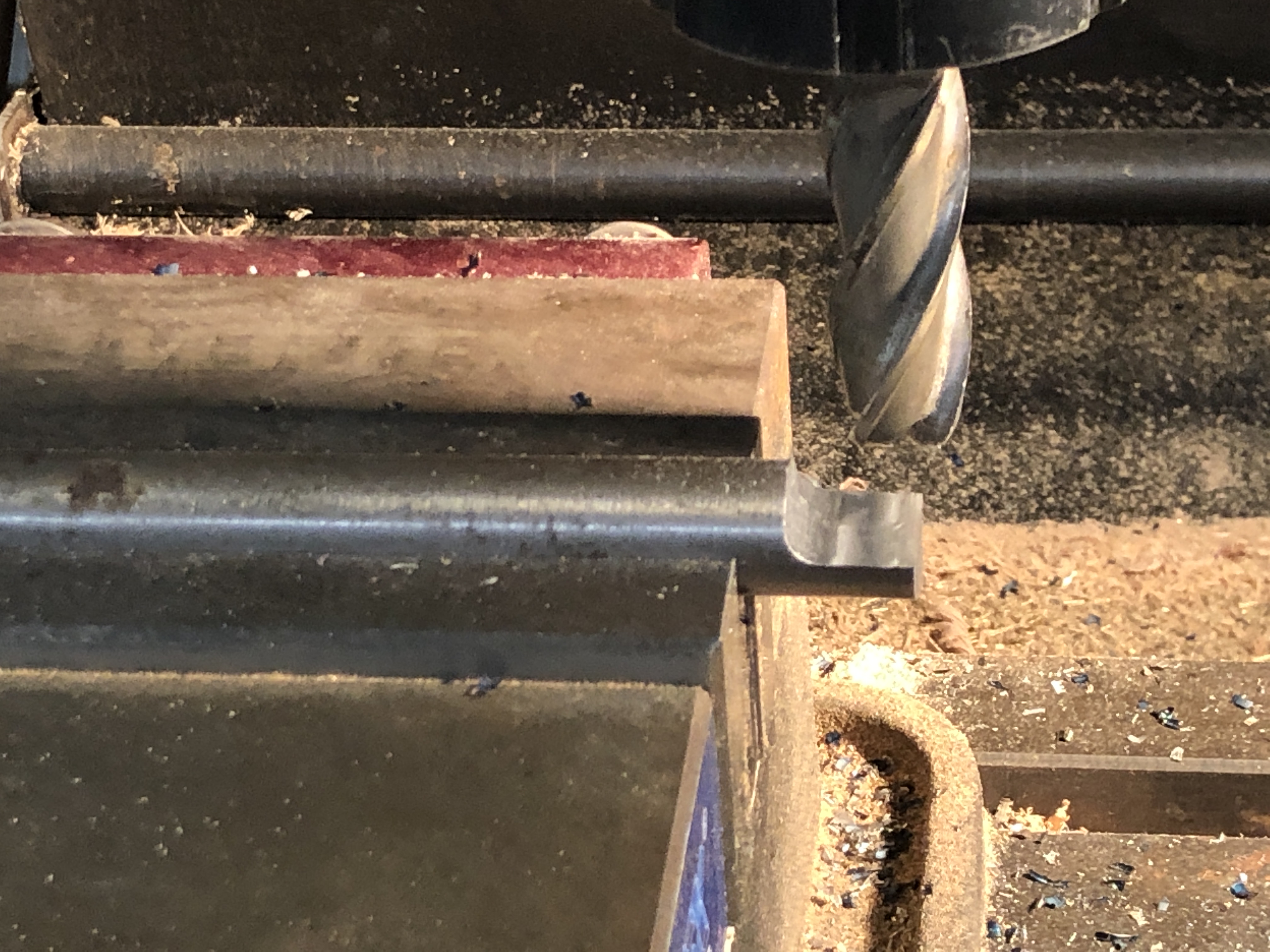
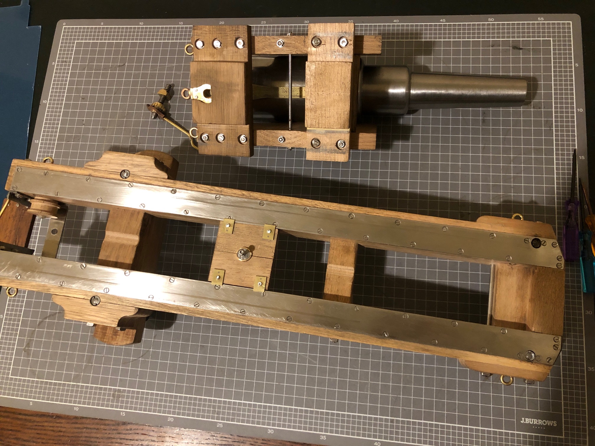
1. The 2º canting of the rear sights was established with 8mm and 10mm thick parallels sitting on 1-2-3 blocks under the trunnions. There is an 18mm rod in the bore, sitting on the jack to hold the barrel horizontal. A 4mm end mill is creating a flat surface from which to start the drilling.

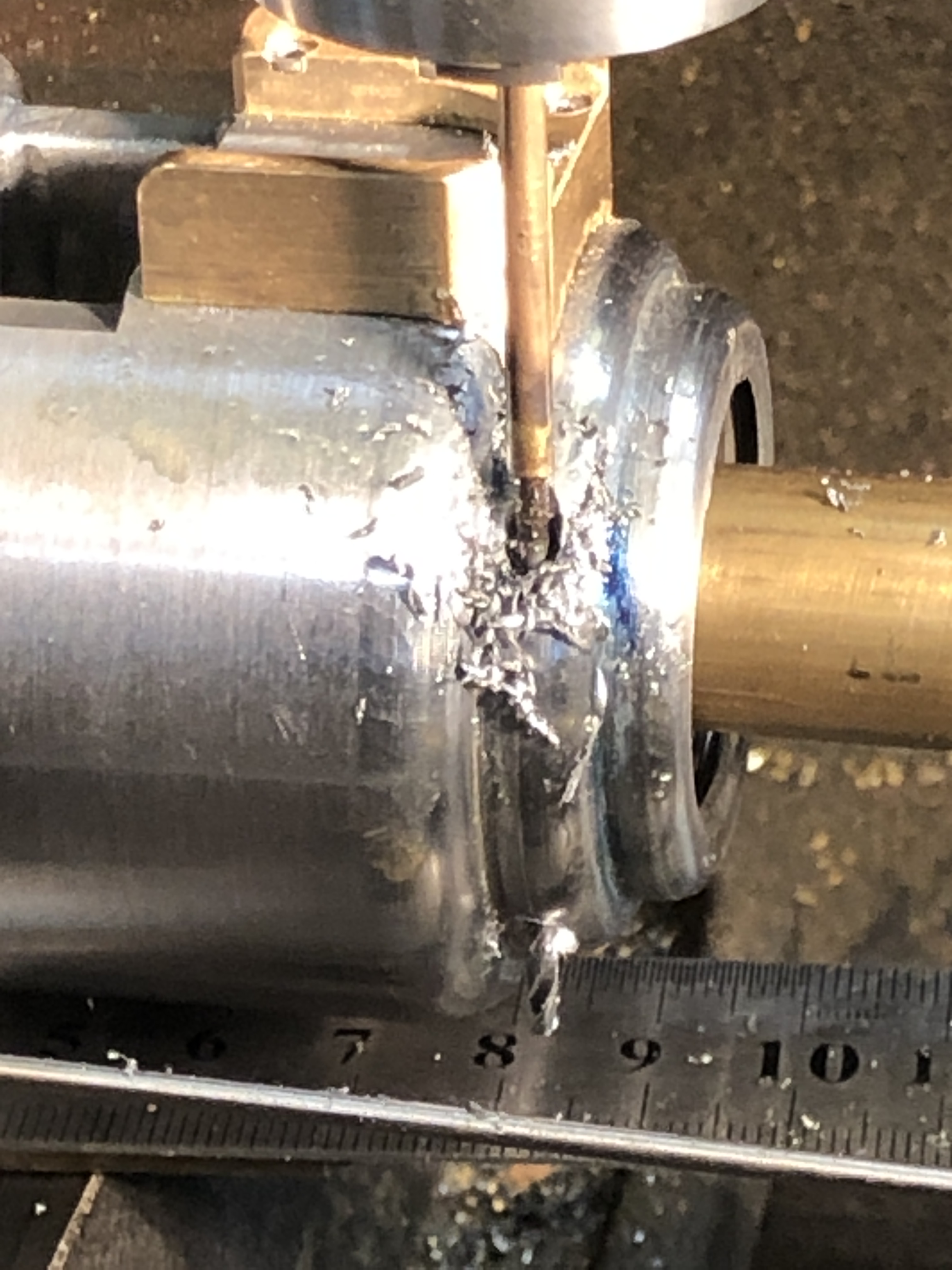
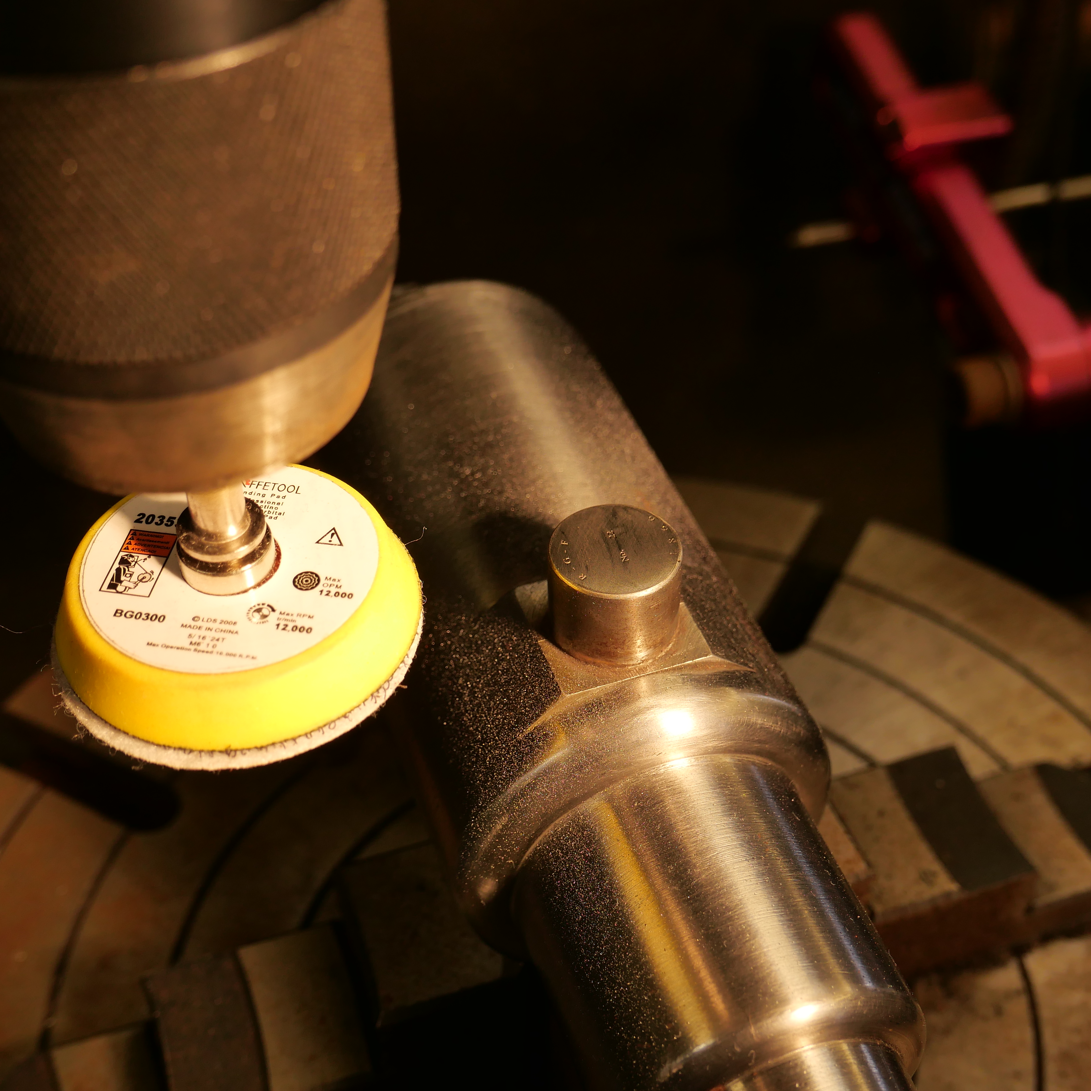
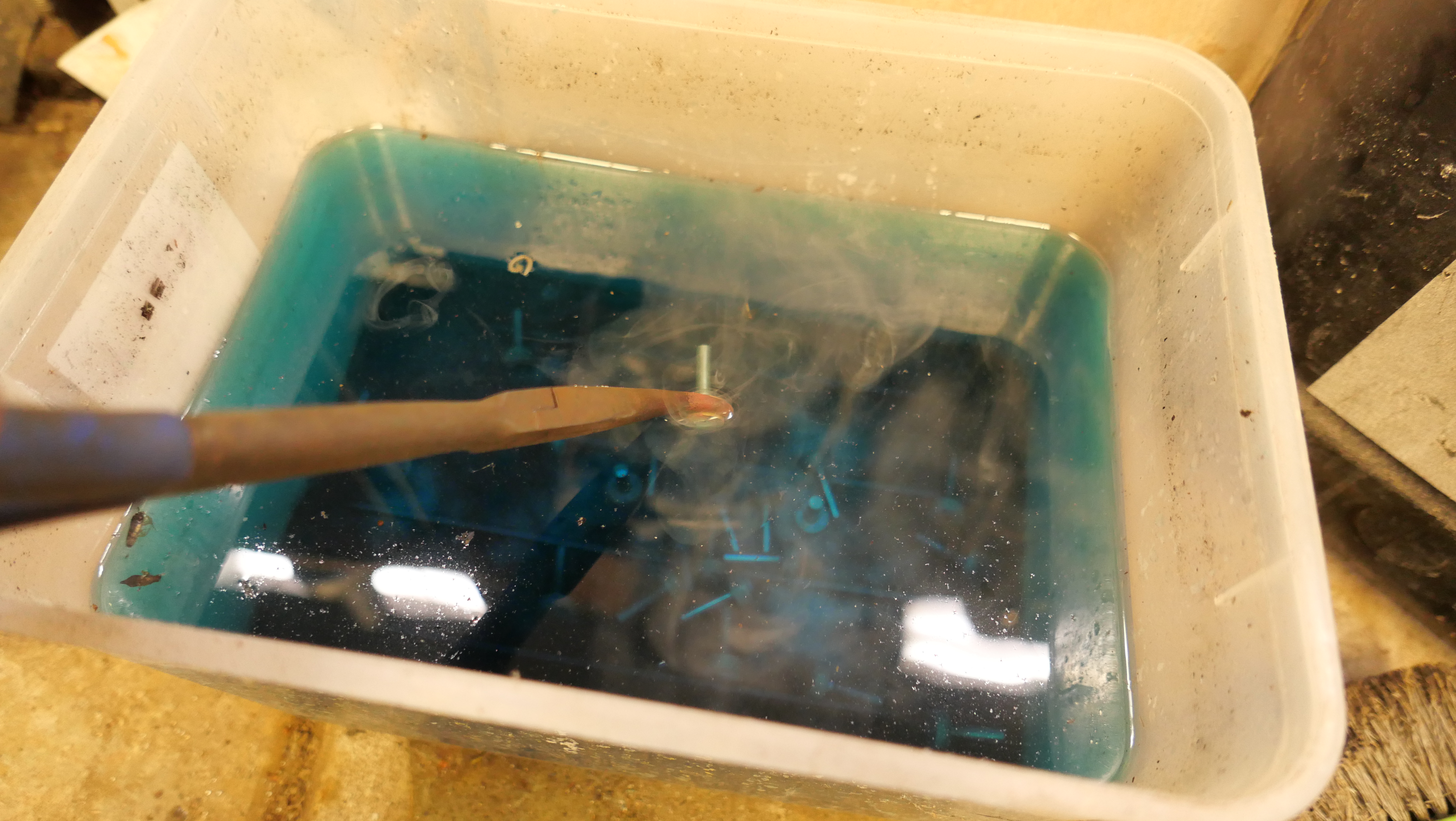
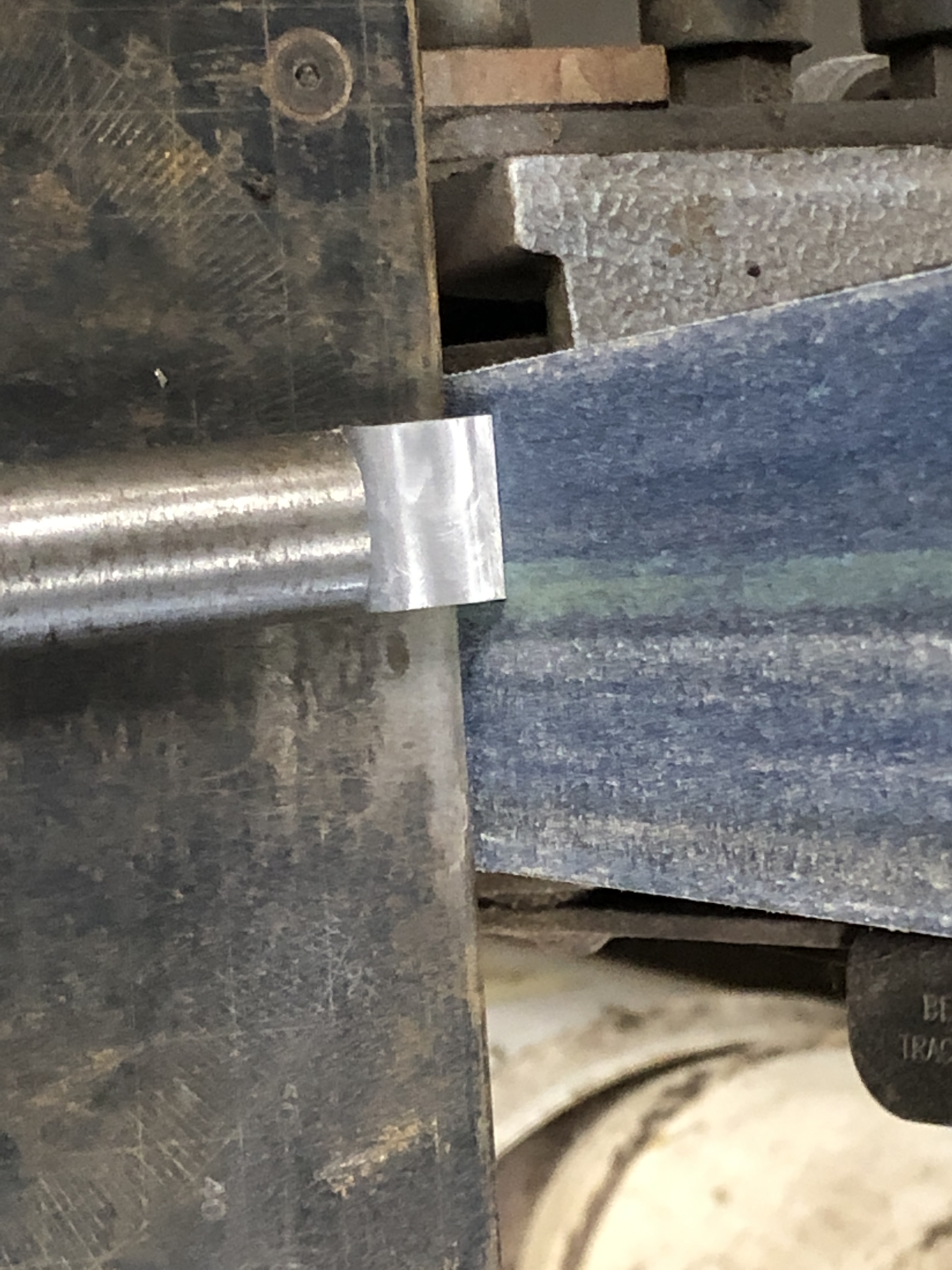
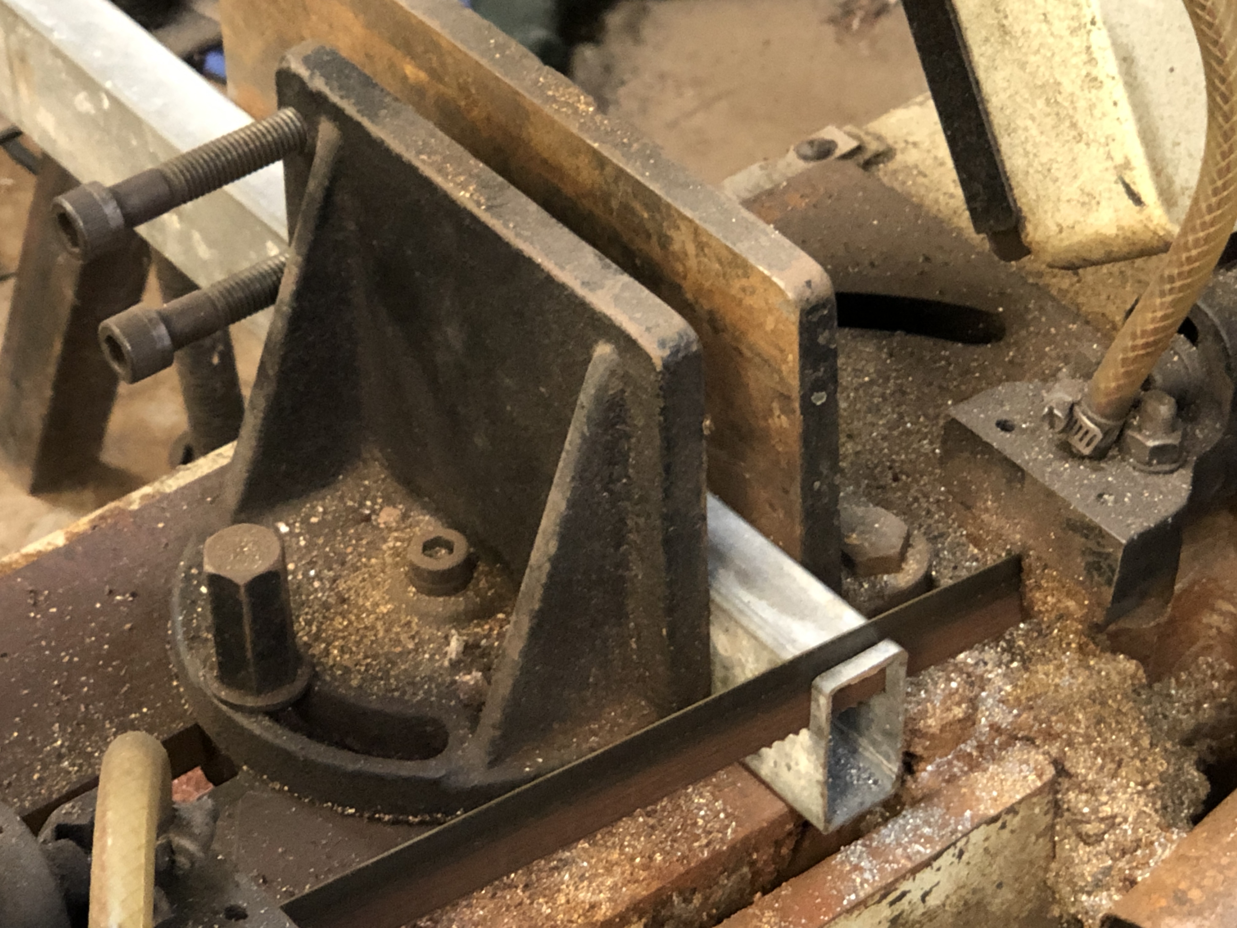
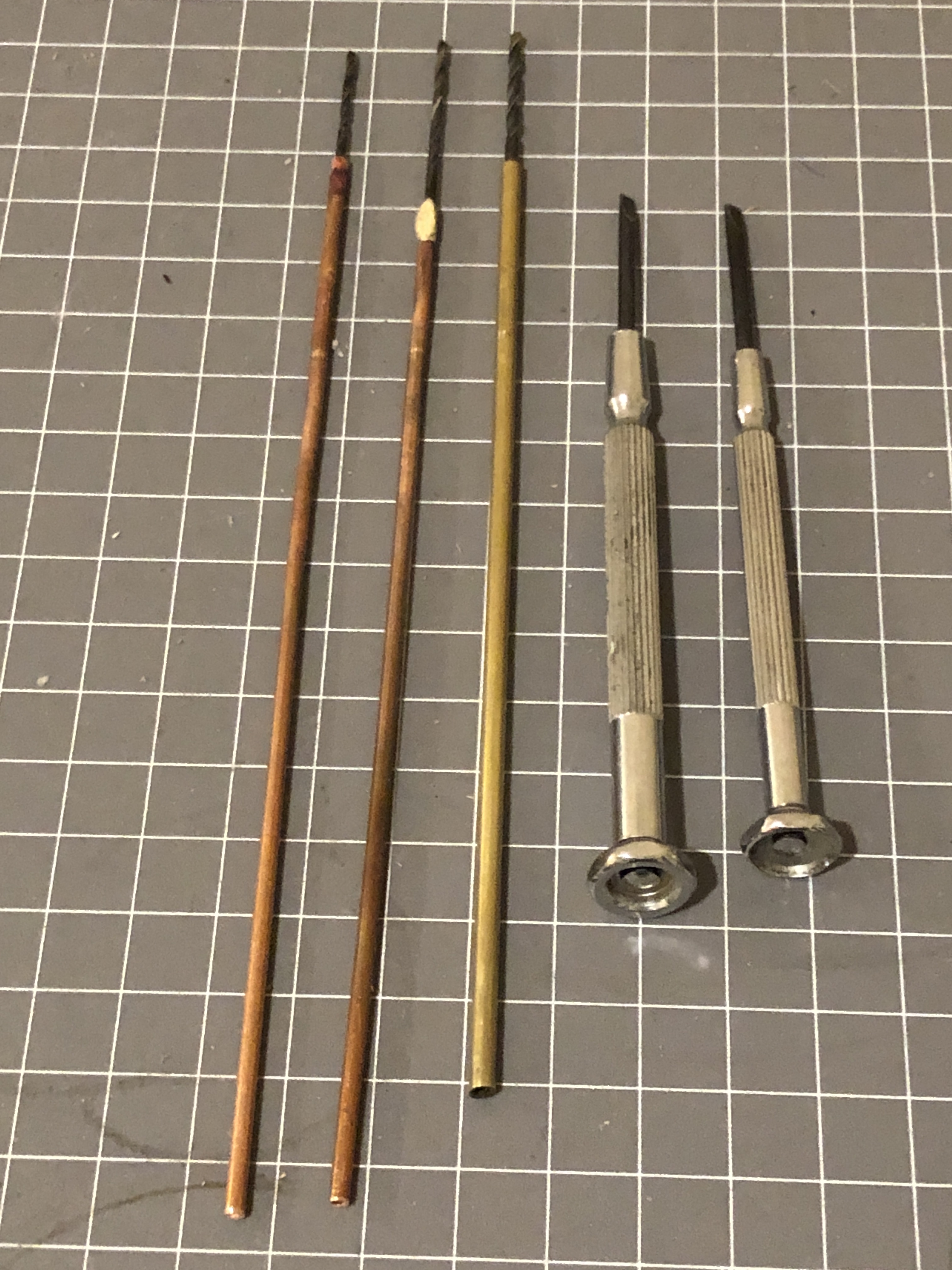
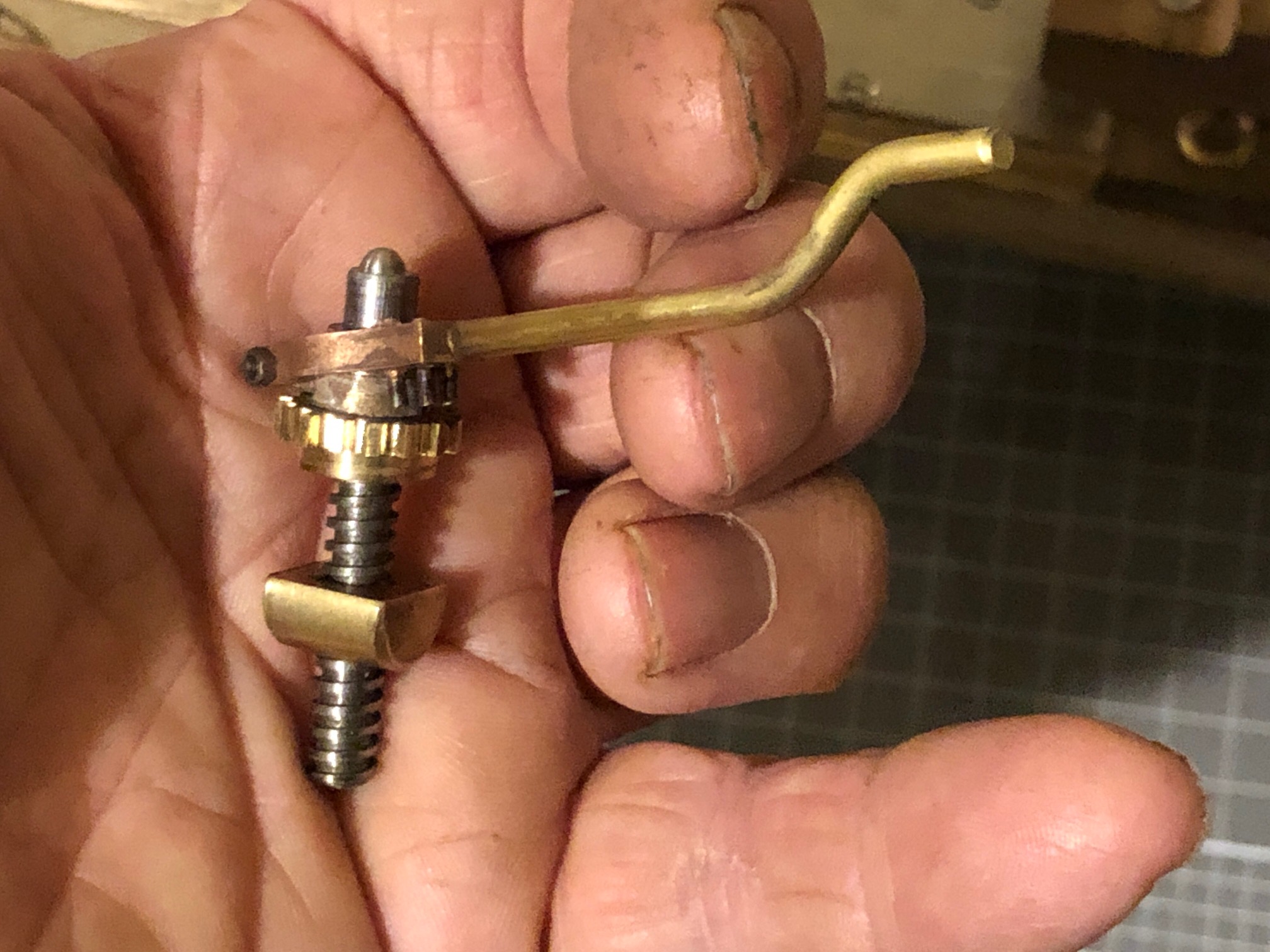
2. That is a 2mm drill bit, silver soldered to some pipe to give it some extra length. “Tension drilling” again.

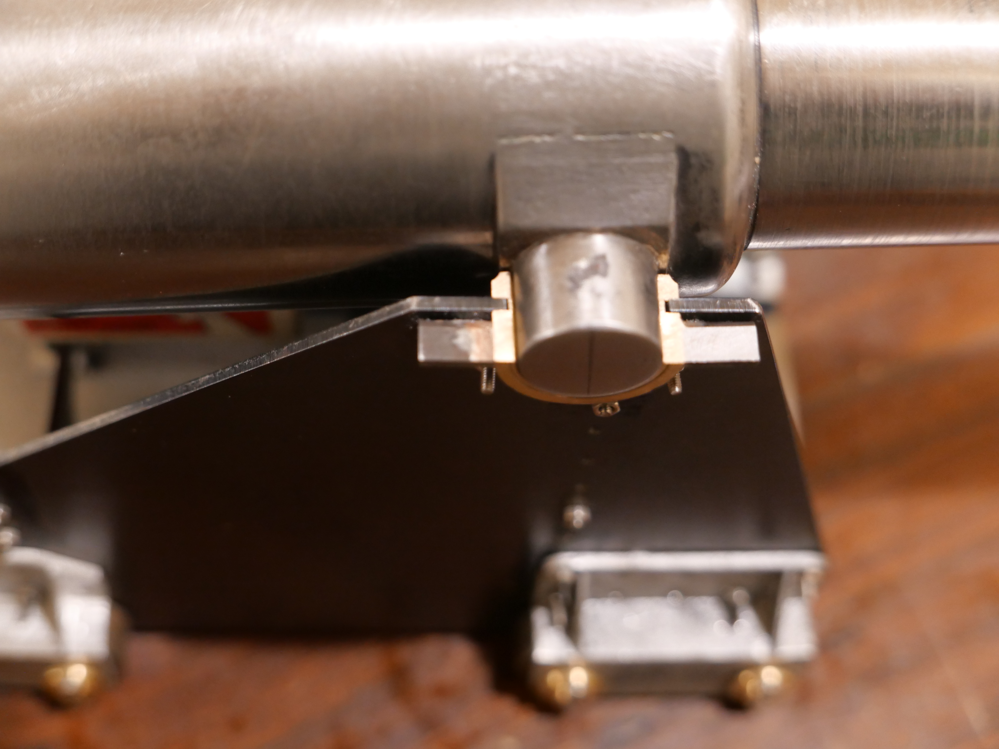
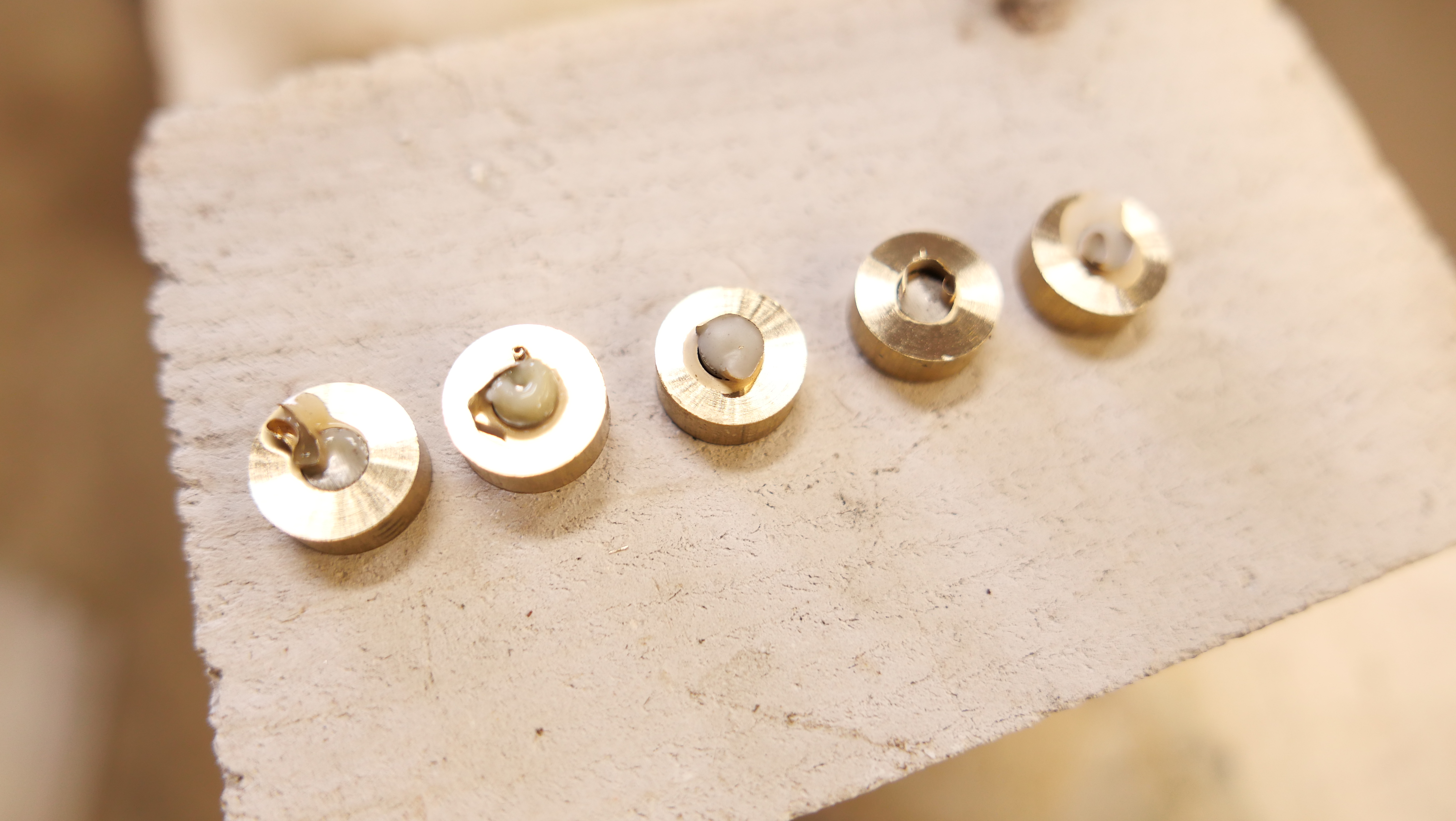
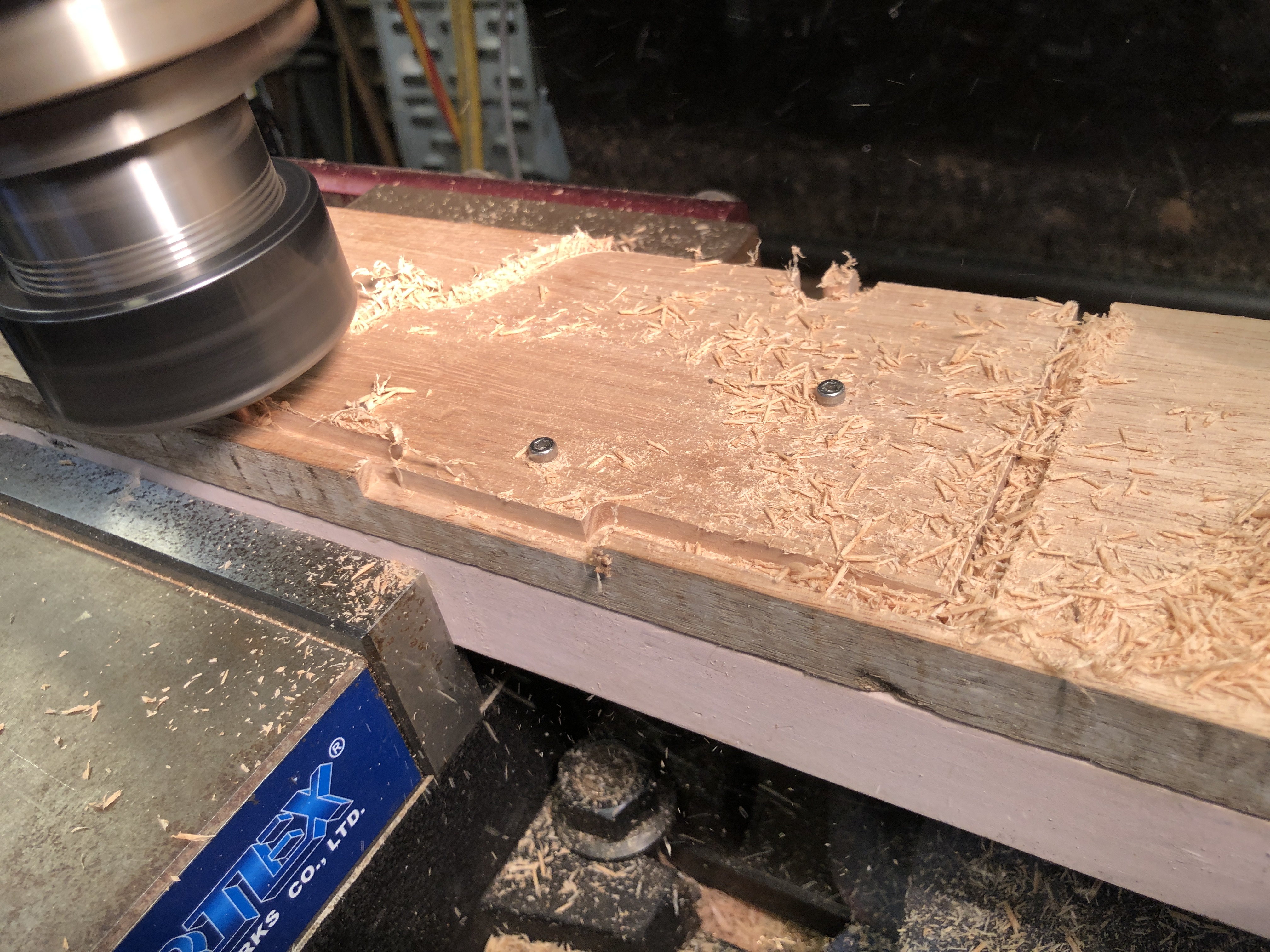
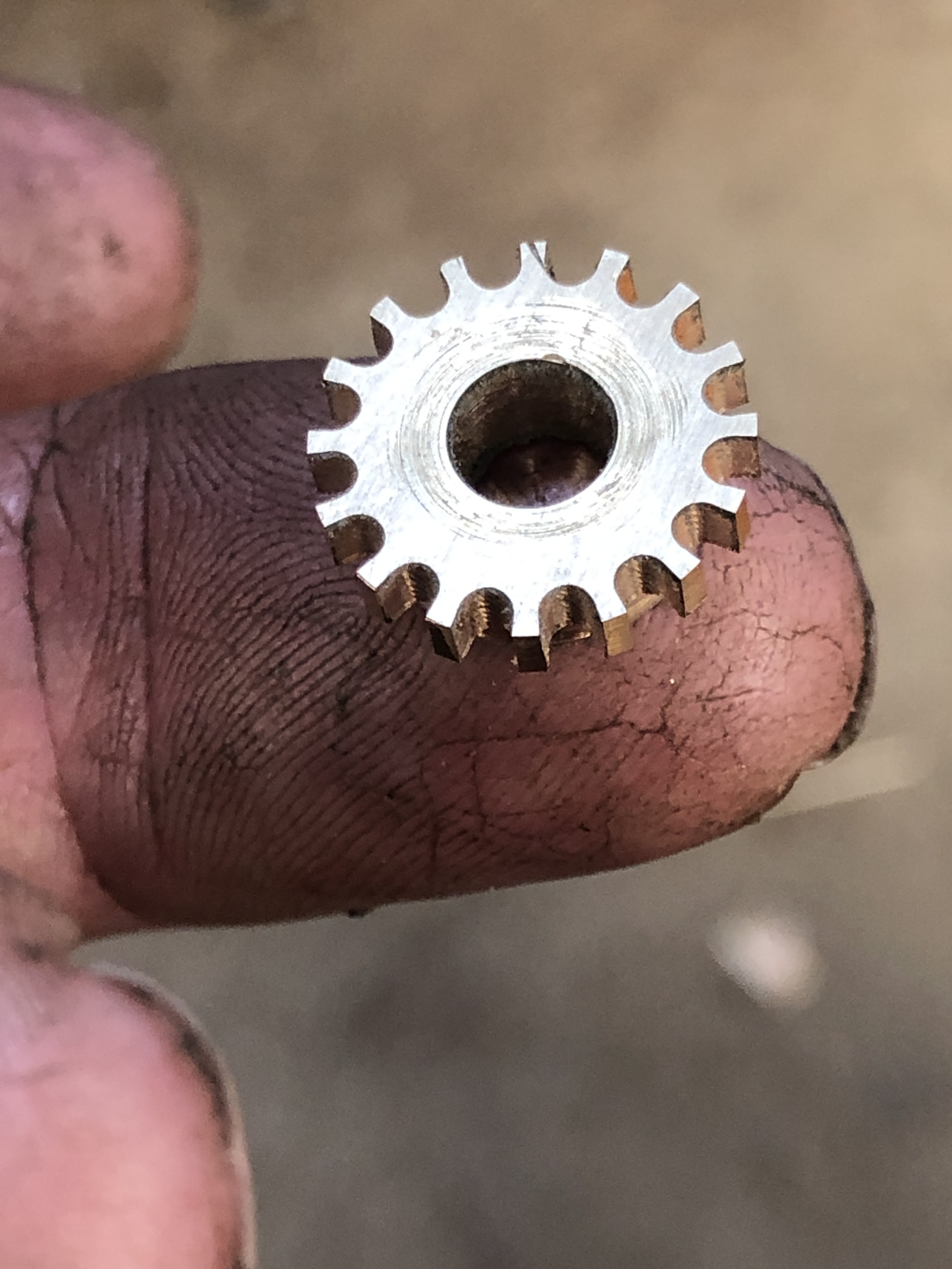
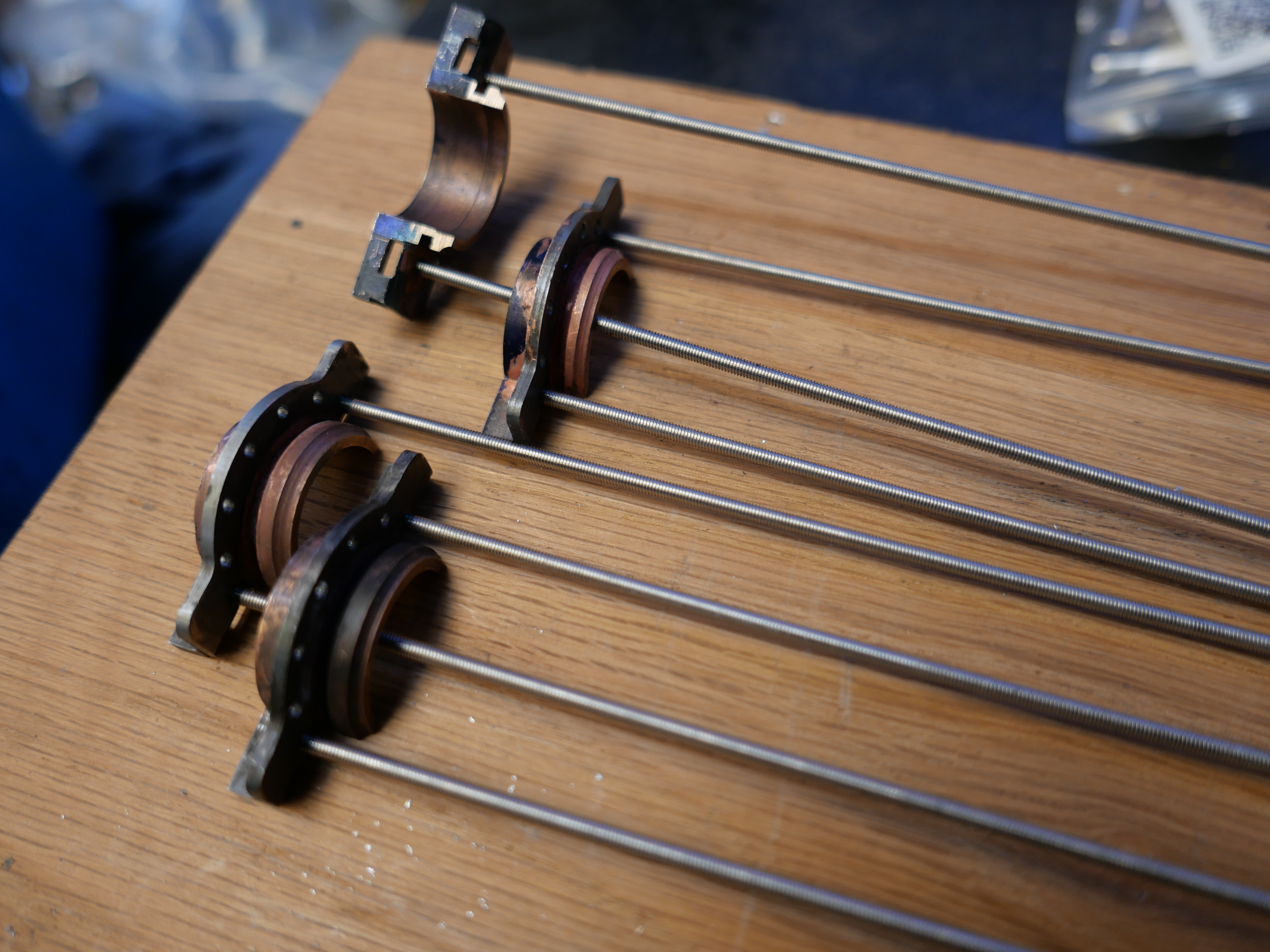
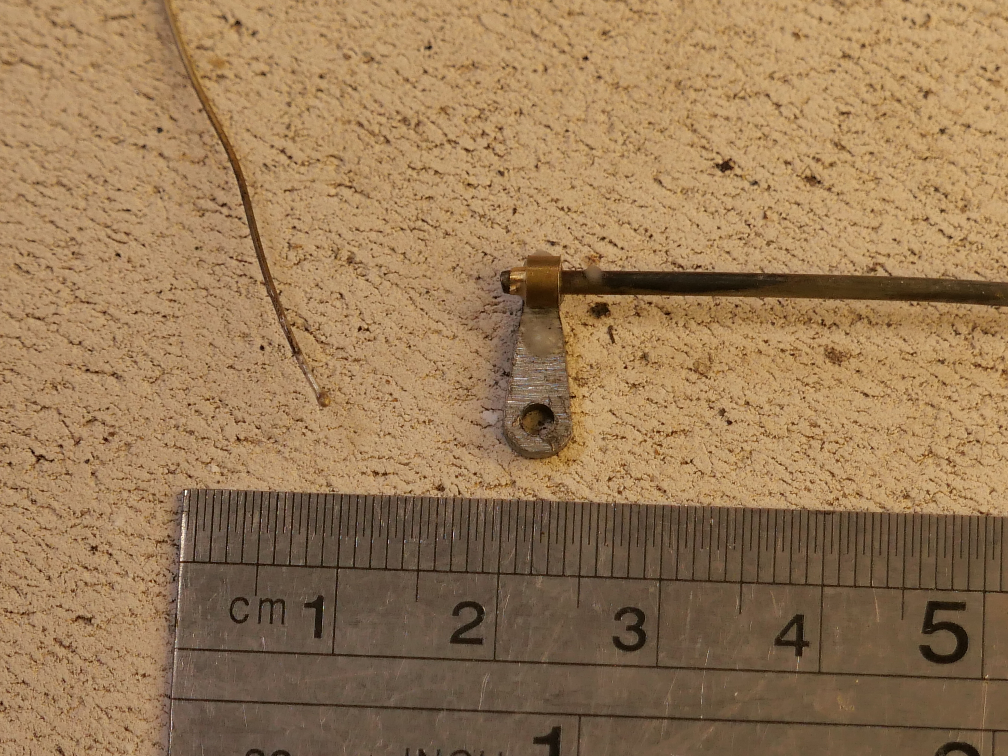
3. Checking the lengths of the foresights.

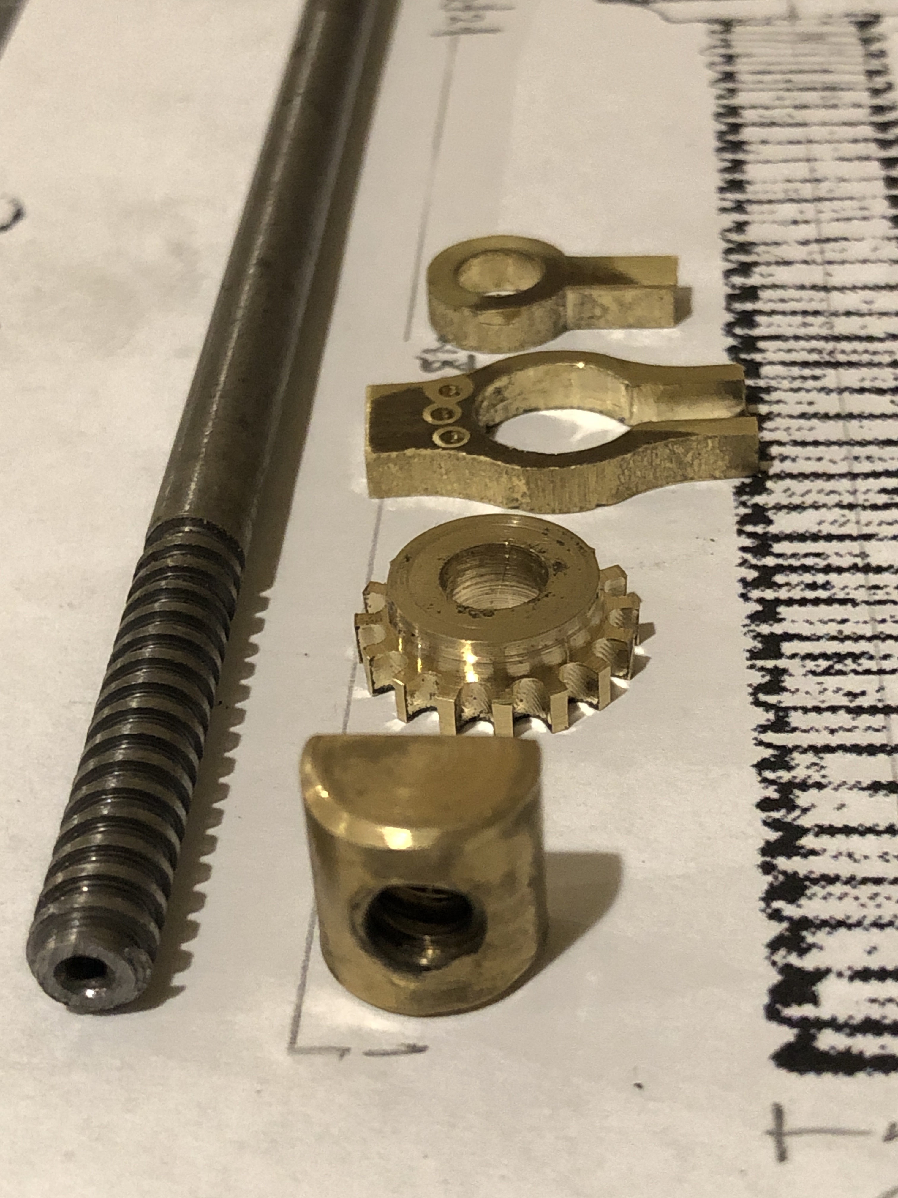
4. The almost finished sights. Left rear holder needs to be shortened. And yes, the magnified photo does reveal a previously undetected superficial crack in the left weighted arm. Luckily I have a spare part if it breaks. I must have used too much force when I pressed in the driving pins.

This series of posts is almost complete. Making the 1:10 scale model Armstrong Breech Loading, Rifled cannon, 110pr* took almost a year, and these posts were originally published by johnsmachines.com in wordpress.com. Since I am intending to cancel my subscription to WordPress I have decided to transfer some of the 900 posts to this new, for me, site.

Further old posts will gradually be transferred. And some new ones will be appearing.

Trunnion Rings Completed.

Today I turned the trunnions.

1. The centres were measured, marked and drilled. The squared end was held in a 4 jaw chuck and the end to be turned was held in the tailstock. Turned to 20mm dia with a “Diamond” tool holder and HSS 1/4″ cutter from Eccentric Engineering.

2. Then the turned end was held in an ER40 collet chuck to avoid marring the surface, and the tailstock end was turned.

3. One finished, one end to go.

4. Then I used the undersized laser cut parts to turn another “coil” (solid steel in the model, not a wound coil as in the full size cannon), also to be heat shrunk to the barrel.

Next step will be to turn the barrel diameter down to about 0.06-0.07mm bigger than the internal diameters of these parts. I will try to take some photos of the heat shrinking process for the next post.

Armstrong 110pr Cannon Model-3

This project is progressing slowly. Other issues are taking time at present.

There are 3 major components on these cannons…. the traversing platform, the wooden carriage, and the iron barrel. And a number of smaller components… the compressor (the recoil suppressor), the elevating mechanism (Smith’s screw), the sights, and various rope eyes.

I usually have something in mind to work on when I enter my workshop, but sometimes I just proceed where the mood steers me. I have actually been working on all 3 of the major components, with most progress on the traversing platform, which explains why the posts have been rather fragmented. Most of the work so far has been woodworking, but recently I had an urge to do some metalworking. So I made a start on the barrel.

The first step was to buy and cut to length the 1020 steel shaft. Then the piece was mounted in the 4 jaw chuck, and dialled within 0.05mm at the chuck. The tailstock end was supported in the fixed steady, and also dialled in. I was not trying for perfection because it is a case of time and diminishing returns, and straightness of the bore and concentricity between the bore and the exterior of the barrel are the main concerns.

So, the next step was to drill the bore to 16mm, using the extended drill bit which I had fabricated for the previous cannon, after centre drilling. The resulting hole was 305mm long, appeared to be straight, and just a bit rough.

Drilling the 16 x 305mm hole took 15″. I touched up the drill bit cutting edges with a diamond lap, and cleared the swarf every 10mm or so. Plenty of cutting fluid used.

I wanted a final bore of 18mm diameter. I have an 18mm reamer, but only 120 mm long, so I made an extension rod to fit the Morse 3 driving tab. But first I had to drill the bore closer to 18mm. So I made a D bit from undersize 18mm drill rod.

The silver steel / drill rod is 17.94mm diameter. The flat is milled, removing 8.94mm and leaving ~9.0mm. The cutting end was hardened by heating to cherry red , then quenching in oil. It was still able to be filed, so not hard enough, so I repeated the heat-quench cycle, using a water quench, and that worked well.
Using the belt sander to give some side and rear relief. Later I added a chamfer to the cutting corner (see next photo).
Cutting corner on the left.
The “business end” as requested by John Marshall. This is after cutting through 305mm of 1020 steel, and it needs another touch up with the diamond lap. initially I used the D bit as shown on the belt sander above, but the cut improved after the bevel was added with relief to the cutting corner. The only purpose for the recess is to accumulate swarf during the cutting process. But the recess fills quickly and it needed cleaning out every 5-10mm of drilling depth.
The D bit was held in a 40ER collet in the tailstock. Plenty of cutting fluid was used. The chips were cleared every 5mm of cut. The D bit was sharpened 3-4 times during the process using a diamond lap. Enlarging the bore to 17.95mm with the D bit took 15min.
This was taken after using the D bit. The surface finish was improved further after passing the reamer. I am not concerned by the rough appearance at this end because it will be machined out to 28mm for a depth of 50mm to accomodate the breech screw and breech plug.
The breech screw is shown in drawings of the era as a buttress thread, with a pitch of approximately 1.25″. I have some 1.25″ diameter threaded rod, category H2, with a pitch of 1/8″ which at scale 1:10, is very close to the original, although not buttress profile. The drawing is very close to full size for the model. I drilled, D drilled and reamed the through hole, and am considering how I will cut the thread into the breech of the barrel. Still pondering whether to try to cut a buttress thread…

And the traversing platform now has the metal surface strips screwed into position..

The 1mm thick stainless steel strips had been laser cut and 2mm holes laser drilled. I had to countersink the holes so the screw heads were at or below the surface, so provide a smooth surface for the carriage slides and trucks (wheels). The countersink tool is carbide. I wanted a smooth flat surface to work on, so used a fly cutter on the wood to produce such. The counter sink bit self centres well.
The screws are 1.6mm diameter. In that size I had to settle for Phillips heads rather than simple slotted. The larger circular cutouts are for the wheel posts, yet to be made.

Armstrong 110pr Breech Loader-2

Having commenced building a 1:10 scale model of this gun on a wooden carriage and traversing platform, I am also finding information about its history. First the build progress….

Glueing the traversing platform pieces. And a 4mm long series drill bit.

Gluing required some planning. The brass stops rebates were tricky to make last time because the platform was already fully assembled. So this time I made the rebates and installed the stops prior to gluing up.

Then there is the matter of the long, 4mm, holes across the multiple pieces of the platform, which is up to 152mm wide. Wood is not uniform like steel or aluminium, and deep drilling wood with small diameter drill bits usually leads to wandering crooked holes. So I measured and drilled each piece separately, prior to assembly. A tricky and exacting process. All except for the outside pieces shown being clamped above. They were drilled, one side at a time, after that side was glued, using the existing holes as a drill guide. I was happy with the results of the drilling and gluing.

Cutting out the carriage cheeks with a 6mm endmill. The workpiece is screwed to the sacrificial base piece with large woodscrews (not visible), then the required holes for the model are drilled through workpiece and sacrificial base and bolts are inserted. These bolts stop the workpiece from moving in the final stages of cutting the part free. The carriage cheeks will not be parallel in the final assembly, being narrower at the rear than the front, and the holes will need to be modified at that stage, so I have drilled them undersize at this time. Same goes for the trunnion cut outs.
Glued and drilled traversing platform (one of 2); laser cut 1mm stainless steel strips ready for attachment (AUD$55 including material. Probably saved me a day and more accurate than I would have managed), and CNC cut carriage cheeks, straight off the mill. Recycled Victorian Mountain Ash floor boards).

Not so much workshop time lately due to family factors, so I have been reading and searching references. And thinking about how to machine the barrel. Important to get the sequences right. And to have available the correct tools.

A is the screw which compresses the breech block E into the copper seals F and H, after the projectile and charge have been loaded through the breech. B is the weighted handle which operates the screw. C is the breech coil. D and J are further coils. K is the trunnion piece which was forged including the trunnions.

The originals were made using the Woolwich “coil” system, in which components of the barrel were made into various sized and shaped cylinders by winding white hot strips of iron or steel around a mandrel, then hammer welded into a single fused mass. The various cylinders were then accurately turned on large lathes into the final pieces which were heat shrunk together, and finally furnace welded. The Armstrong 110pr had 7 such major pieces. Only the innermost barrel cylinder was steel.

There were 2 barrel designs of the 110pr guns. The above diagram is the 72cwt version, which was 2″ shorter than the 82cwt version. The latter has more taper to the chase of the barrel, and will probably be the one which I model.

The 2 types of 110pr barrels. You can see my metric conversions of the dimensions. And a few dimensions scaled off the drawing. I think that I will make the 82cwt version.

I will not be making my model using the coil method, but I am probably going to make the trunnion ring with trunnions as a separate item, and shrink it onto the barrel, along the lines as described by jefenry.com. Still thinking about those big asymmetric double start threads on the breech screw. I have a high tensile 32mm bolt and nut which I am considering using.

The scaled bore should be 17.78mm. I will approximate that to 18mm. Will need to extend a 17.7mm drill bit, and to make an 18mm D bit from silver steel. Jefenry welded an extension to an adjustable reamer to finish his bore. I will possibly use that technique also.

Gunners Side Platforms

These daily posts might be becoming a bit tedious but you need to realise that I write them for my own diarising purposes as well as entertaining yous.

First today, I deepened the countersinks on the carriage stops which I had installed yesterday, and filed the bracket surfaces until the carriage showed no signs of catching on high spots. Then reassembled all of the bits in the vicinity.

I had machined some hardwood (Australian Mountain Ash, a close grained, hard, stable, pale hardwood) for the side steps, and today I made the brackets to support the side steps.

There are side steps on both sides. The one not visible is smaller. R1 R2 and R3 are the steel supports.

But, when I examined the steps today, I decided to remake the side steps, using the dark red hardwood Jarrah, the same as the rear platform.

The Jarrah side steps. They will age to a dark red colour, like the rear platform. The grey desk mat is A2, to give you an idea of the scale.

The steel brackets were cut from 50mmx25mmx1.5mm rectangular section tube.

Cutting the RSS.
Bolted to the side steps. They look a bit rough at this magnification. The lip at the top is cold bent.
The U bolts are bent brass rod. I intended to Loctite them into the drilled holes, but they needed to be hammered home, so I think that glue will be unnecessary. (I made 2 extra)

So, I think that those are the final parts to be made for this model. Now I need to decide about finishing the wooden surfaces. At this stage I am thinking of a dark wood stain, then a satin finish with a wood oil.

Traversing Platform Floor, and Carriage Recoil Stops.

Firstly some woodworking to make the platform floor. Basic machining, drilling and screwing.

Quite pleasant to do some basic cutting on the bandsaw and thicknessing on the mill. HSS metal mills give a good finish on hardwood. It was finished quickly, and went so well that I proceeded to a task which I had been putting off, because I knew that it would be very difficult.

I made the carriage recoil stops, and installed them.

The problem was that the platform had been previously assembled, including gluing of the joints. And I was not going to break those joints for anything.

The recoilatop is on the inside of the platform slides, at the rear. Shown here above the bollard. It is recessed into the slide so only the actual iron stop is above the surface. Also, it is underneath the bracket which supports the gunner’s rear platform.

The stop bracket is about 30mm x 6mm x 2mm, and the stop protrudes about 5mm further. So the first question was how to make the rebate. The distance between the slides is only 53mm. Not much space to use chisels. And end mills could not be used. The metal surface of the slides is glued and screwed to the slides, so removing those was not an option either. I should have made the rebates BEFORE I glued up the platform. Oh well….

This is the setup which I used….

I bought some Woodruff cutters and T slot cutters at a sale some years ago. So I cut the slots with one of those. The cutter worked well, but it left sloping ends. One of the ends is hidden behind a bracket, but the other one is visible. Used the inspection mirror to watch the milling on the near slide.

So how to square up those ends. Not enough room to get a chisel into that space. Still wondering, I made the actual stops.
Making the stops involved some basic milling and silver soldering. The steel nut got a bit chewed up during the slotting. It will not be visible in the final assembly.

Then, rather than squaring up the recess, I rounded the hidden corner of the stop bracket. Easy!

Drilled the holes in the stop brackets for the screws, fitted the stops into position. Now, how to drill the holes in the wooden slides for the screws? The holes in the wood were only 1.4mm diameter. And a 1.4mm drill bit is not long enough for the drill chuck to miss the other slide. To avoid the other slide the hole would be excessively angled.

So I used another trick which I have used previously. I silver soldered the drill bit into some fine (2mm OD) copper pipe….

1.4mm, 1.6mm, and 2mm drill bits given substantial extensions. I used copper for the small sizes because I had some suitably sized pipe. I had drilled the hole in the brass rod for the 2mm extension for another model.
The extension meant that there was only slight angulation of the hole when drilled with a battery drill.

I will enlarge the countersink on the stops to bury the screws deeper, then file the screws flush with the stop surface. I doubt that the bit of angulation will ever be noticed. I used steel screws, because a brass one snapped off and I had to drill through the remnants. The steel screws are slightly bigger than intended, but not excessively. I had removed the gunners platform to improve the access. The area will look tidier when fully reassembled.

I am very glad that particular task is all but finished!!

ps. I have called them “stops” but that is probably not the correct term. The recoil of the carriage is reduced by the 5º slope of the slides and the braking from the compressor. The “stops” (or whatever they are called) are the final impediment in limiting the recoil of the carriage and its barrel.

Carriage Wheels-2

The Armstrong 80pr rifled muzzle loader at Hopetoun Gardens, Elsternwick, Victoria. One of two.
On the Elsternwick guns the slides have been covered with sheet metal covers to protect them.

The carriage wheels are at the front of the carriage. They do not actually contact the slides unless the rear of the carriage is levered up a few millimetres, to assist with rolling the gun down to the firing position.

They are constructed of bronze.

On my model, the gap between the wheels and the slide would be about 0.3mm.

Today I attached the wheel brackets to the carriage cheeks (the sides of the carriage).

I had deliberately made them with a slightly large diameter, knowing that I would need to reduce the diameters after they had been fitted.

This is how I reduced the diameters…..

…on a belt sander, holding the oiled shaft in my fingers and using my thumbnail to hold the wheels in position. After a few seconds sanding, and being careful not to sand my fingers, I tried the wheels on the carriage, rolling it up and down the slide. That was repeated multiple times until the wheels were just clear of the metal slides.

The single axle will be replaced by more authentic appearing separate axles with dome heads and pins. The brackets will be let into rebates in the carriage cheeks, and tapered in their upper halves.

Wooden Compressor -2, and Smith’s Screw.

Making scale model components probably takes as much time as making full size ones. Well, with some exceptions. In each part of the compressor for example, there are as many measuring, set-up and machining actions in the model as in the full size part. Finding dropped tiny parts would take as much time as the (considerable) manhandling of the heavy full size ones IMO.

Yesterday for example, I spent about 3 hours deciding how to attach the compressor support pieces, cutting, machining, drilling and tapping the holes, then fitting them.

I use brass or bronze or stainless steel wherever possible. Not always the same as the original, but I don’t want my miniature to end up in the same condition as the originals in another 150 years. The brass tabs were placed as close as possible to the corners, but avoiding the long bolts holding the leaves together.
The underside of the compressor. 10BA bolts. Wood gets grubby in the workshop. It will require a good solvent cleanup before finishing.
To demonstrate the compressor location. It sits on the metal slides, and between the cheeks and cross pieces (transoms) of the carriage.
The Smith’s Elevating Screw is finally complete. Here showing the pins which engage with the gear to turn the screw. The handle spins freely on the screw shaft. The hemispherical top sits in a corresponding hole in the bed plate. I am satisfied with this interpretation of the limited information available about the Smith’s Screw.

Smith’s Screw -3.

Another half day workshop session saw some more small parts made for the Smith’s Elevating Screw at ~1:10 scale. As close to 1:10 scale as possible, but I decided to make the parts about 20% bigger than the dimensions I scaled off the poor quality drawing, to fit with small drill bits and end mills in the tiny end of the range. The smallest end mill which I used was 1.5mm diameter!

CNC Drilling the gullets in the gear with a 1.6mm drill bit, after turning the OD of 15.9mm. I made 2 of these parts, just in case.

This is the gear after completing the gullets with the 1.5mm end mill. 3000rpm, 0.5mm depth of cut, 30mm/min feed rate. (metal working is not great for hand beauty)

The Smith’s Screw square thread, yet to have a hemispherical head turned after sawing off the excess length, the brass half cylinder nut, the gear, the yoke and the shaft bracket. A hinge pin will be inserted first, then some relieving of the hinge edges. The yoke and shaft bracket were CNC’d from 3.5mm brass plate.
and a handle to be added, and a restraining collar. Oh, and the 3 steel driving pins to be silver soldered in the yoke holes.

One more session should see the Smith’s Elevating Screw completed.

Did you notice that I have modified 6 details since drawing this?

A Hot, Humid Day

Feeling a bit inactive on a hot humid day.

Thought that you might be interested in some more photos relating to RML’s.

That barrel could be an 80pr Armstrong, 3 meters long, which would make the lathe about 8 meters long. Note the date, the taper cutting mechanism, and the fact that they did some external turning with the trunnion ring insitu.
This is said to be the recoil controller from the wooden carriage/platform which is outside the Maritime Museum, Warrnambool. It is apparently an exceptionally rare item. Not on display. Shown to me because I asked questions about the cannon. I could not see how the recoil mechanism would have been fitted or functioned on the particular cannon. Picture of the Warrnambool cannon on its wooden carriage and platform follows. The loose metal objects on top are not related to the recoil mechanism.
The preserved, protected, and unrestored condition is very useful for modelling. LowMoor 68pr SML. 1861.
I have possibly shown this photo in a previous post. It is the 1866 80pr Armstrong RML on wooden carriage and platform at Fort Queenscliff, 30″ drive from my home. Missing the Smith Screw, sights and gunners side platforms, but otherwise in reasonably complete condition. No evidence of a rear gunners platform. Front left wheel bracket needs some attention.
and just to complete the photo collection of 80pr’s on wooden carriages and platforms, I revisited the Elsternwick cannons recently to get some more measurements. Early evening photo. Note the bolts hanging under the slides. They do not exist in any of the old drawings or photos. Maybe this one had a pivot support originally. Some of the very early platforms did have pivots, but they were removed as being unnecessary, and liable to damage when the gun was fired. Also note that none of these guns had trunnion caps, which were considered unnecessary in garrison guns. The trunnions do however sit slightly deeper than half way in the carriage cut outs.
For a bit of perspective I add this photo of manufacturing a 16″ barrel in WW2. USA factory.

Hot Weather. Smiths Elevating Screw.

We are having a La Nina summer. Relatively cool and wet. Humid. But, it is summer, and week long spells of over 30 degree centigrade days are expected, even in a “cool” summer. Today it will be 33c with high humidity, and those are not factors consistent with a pleasant workshop experience. So I will stay home and plan ahead how to make several components for the model Armstrong 80pr cannon on the wooden carriage and slide.

One item is the elevating mechanism for the 4 ton barrel. Several readers have helped with information about the mechanism, which I now believe to be a “Smith Elevating Screw” which adjusts the level of a heavy hinged iron bar, on which sits a wooden wedge called a “quoin”. The breech of the barrel sits on the quoin. The quoin is the coarse adjusting component, the screw is the fine adjusting mechanism.

This is the carriage and traversing platform which I am modelling at 1:10 scale. The barrel is an older smooth bore muzzle loader, but the dimensions of the carriage and platform seem identical to those of the 80pr Armstrongs at Elsternwick which I am modelling. The screw and quoin and iron bar are at the rear of the carriage.


Another 19th century drawing of the wooden carriage and platform, with a 110pr breech loading barrel. Also showing the Smith’s elevating screw.
This is the only picture which I could find with any detail of the Smith Elevating Screw.
….and this is a 1:9 miniature Smith Screw, made by Jefenry for his Armstrong 110pr breech loader, and whose videos I have shown in an older post. Those You Tube videos are really interesting to watch. Just do a search on “Jefenry”. These pictures are very useful to me. Thank you Jefenry!
And finally, a couple of recent photos of progress on the model to date. The Smith’s Screw fits into a half cylindrical nut which sits in a bronze enclosure within the rear transom.

Bronze Tyrannosaurus Rex

Actually, I had some spare space on the tree which I used to make some more small gears, and I had some PLA T. Rex’s, so I added one.

P1074321

And this was the cast result, in bronze.  Yet to be cleaned up, tree bits ground off, and polished..

P1074328

 Again, the gears are close to perfect.  I like bronze.

And the gears have a short length of shaft, printed in PLA and cast in bronze, which I will be able to hold in a chuck for tidying and turning.  Lesson learned.   Think ahead, how the cast part will be machined….

And at our society Zoom meeting, Frank M  asked about the colour of burning Borax.   I could not remember, so took a shot today…

P1074324

I would describe the colour as white-gold, with a touch of green.  Like a volcano.   Maybe I overdid the Borax?

Oh.  And I had a brainwave.  When degassing the investment mix with negative pressure, add some vibration.  I tried applying my sanding machine once, and filled the room with old fine sawdust.  But for this session, I placed the vacuum pump on the vacuum chamber, and could hardly believe the volume of air which came out of the mix.  The best degassing to date.

P1074323

and it takes less bench space.   A no-brainer.  Try it!


Soft Jaws

The bronze gears which I cast yesterday were cut off the tree with small bolt cutters, band saw and hack saw.   Then a belt sander to reduce the daggy bits.

P1074316

The gears, and the tree trunk and branches which will be remelted.

P1074317

The faces needed to be flattened in the lathe, but how to hold the rather thin, delicate, irregular gears?

Soft jaws.

Soft jaws made of aluminium, and exactly machined to match the external diameter of gear teeth, so there are multiple contact points, and minimal chance of damaging the teeth.  I made these soft jaws ages ago, for just this sort of job.

P1074318

The soft jaws are machined to exactly fit the workpiece.

The soft jaws may be used multiple times, machined to shape each time.  Very handy in this situation.

P1074319

The larger gears are good.  I silver soldered some extra material on one of them for the shaft, then turned the shaft to size .  But, holding the small pinion gear is more problematic.  I will need to machine a soft jaw with a taper to hold the teeth.  Next session.  I should have anticipated this situation and designed the gear with a shaft to be PLA printed as one piece.


Trunnion Mounts -3

I did not expect these mounts to require a third day session, and they are still not finished!

I discovered that two of the drilled holes in each bracket were in the wrong position, by approx 1mm.  That is a really bothersome error, because the correct position includes half of the existing hole.

I managed the problem by threading the errant holes, and Loctite gluing in some threaded rod.  Each rod was trimmed flush with the surfaces.   Then drilling the new hole, partly through the Loctited metal patch.  That fix worked well.

P1074281

Threaded rod glued into the errant hole.  Trimmed flush later.  Then redrilled correctly.


THE TRUNNION PINS.

The pins hold the trunnion caps in place.  And they took another whole day to make and install.   Ah….  just as well I enjoy all of this.  They are tiny, and I spent at least 50% of the time looking for them on the workshop floor after accidentally dropping them on several occasions.

P1074299

Milling the pin handles from 2mm steel.  The handles ended up at 7mm long.  The holes were drilled before the outlines were cut.  Then the tabs were ground off using my newly made belt sander belt.  The belt lasted 15 minutes before the belt itself tore, with the join still intact!

P1074308

Then some delicate silver soldering of a ring to attach a securing chain later, then the pin shaft itself.  The wire through the ring is just to hold it in position during soldering.

P1074309

And that is one of the 8 pins made.  I will polish them in a gemstone tumbler next session.

P1074310

On the model, the pins are jammed into position with a cam action, after some filing-shaping.  On the original cannon there was a small protrusion on the inner end of the pin shaft, which fitted through a slot in the side of the carriage.  I could not figure out a method of making such a tiny slot (1mm wide x 1mm deep) through 4mm of steel plus 2mm of brass, but the cam action seems effective.    I will attach some chain soon, because I do not wish to make any more of these.  And yes, the pins handles are slightly over-scaled, but I think not outlandishly so.

So, apart from polishing riveting and painting, I think that the trunnion mounts are finished.

Now planning to make the gear train for the carriage positioning on the chassis, and the pinion, quadrant gear, and bevel gears for the barrel elevation.  We are currently in level 3 lockdown for Covid containment, with level 4 looking likely any day, so obtaining brass for the biggest gears is difficult.  I am considering workarounds.  Apparently community anxiety and depression, family violence, and even suicides are mounting.  When I am in the workshop I am in a different world, thank goodness.


Trunnion Mounts -2

It took a whole day making and fitting  the top caps of the trunnion mounts from brass.

P1074265

A 76 x 76mm piece of brass was milled to 10mm thickness.  The trunnion straps will finish at 9.5mm , giving me a 0.5mm machining allowance.

P1074269

The 4 straps were cut out using a new 4mm endmill.  Rounded internal corners were milled square, and the bottom tabs were milled to 2mm thickness.

P1074270

2mm wide slots were milled into the brackets, and ends of the slots were filed square.  None of my rifling files were small enough, so I ground one to size, leaving the faces and one edge  intact.

P1074276

Trunnion mount almost finished.  Pins in the tags to come, and they will pull the strap down tight with a cam action.  The half circle line on the bottom bearing is a painting border to delineate the bottom bracket from the bronze bearing surface which will not be painted.  If you inspect the full size trunnion in the previous post you will see what I mean.

P1074274

P1074273

Now I can take some measurements of the model, and start the barrel elevating gear.  There are 4 gears to be cut, including  bevel gears, handle, shafts, gear case, and some complex mounts.

Trunnion Mounts -1

On the Armstrong 80 lb RML model cannon, the trunnions are secured to the carriage with  steel brackets riveted to the carriage sides, and the trunnions rotate in a bronze bearing.

3404 trunnion L

The original trunnion on the Port Fairy cannon

P1074254

These are the component parts.

P1074238

The RSS ready for cutting out the brackets.  And my working drawing, with alterations.

P1074243

First the 2mm rivet holes were drilled, then the outlines were CNC milled.  The steel is 2mm thick.

P1074246
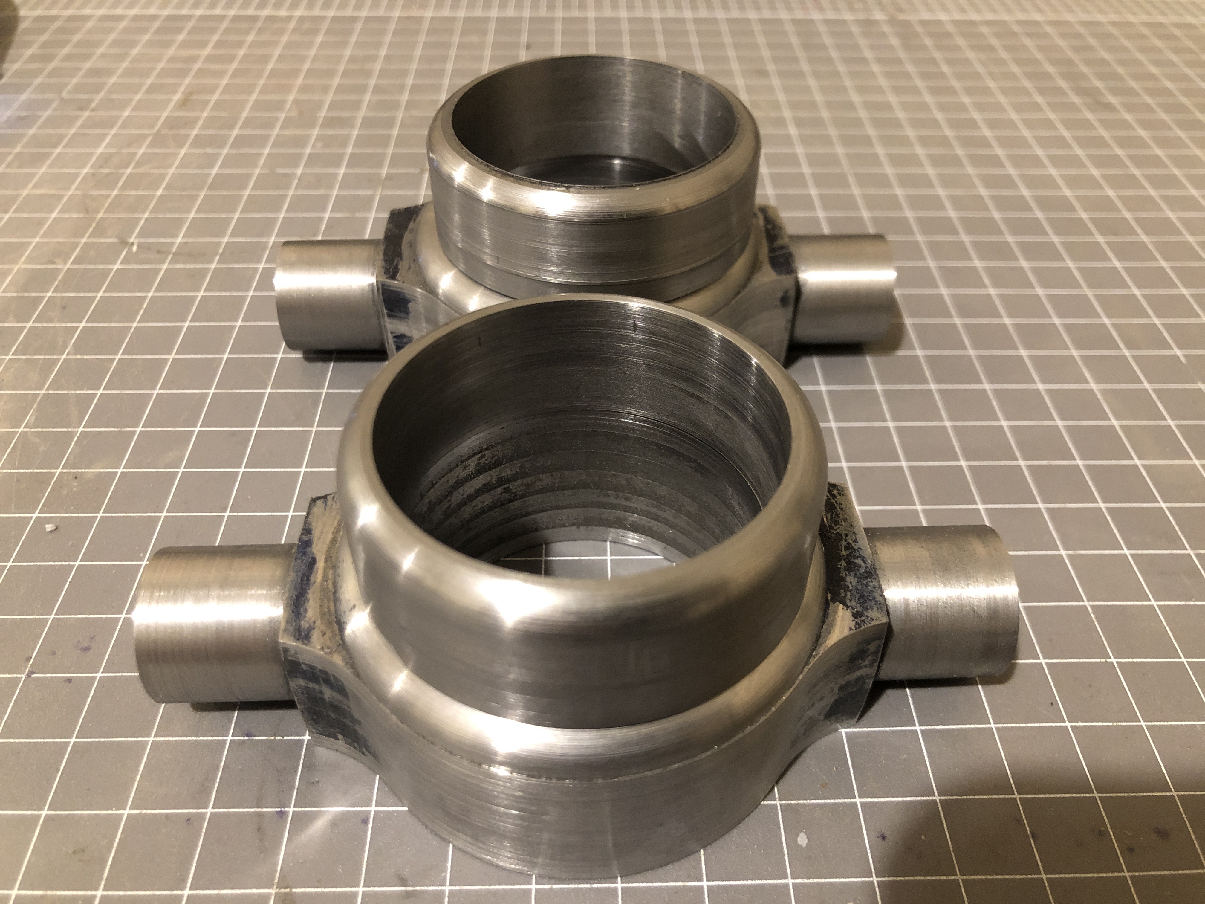
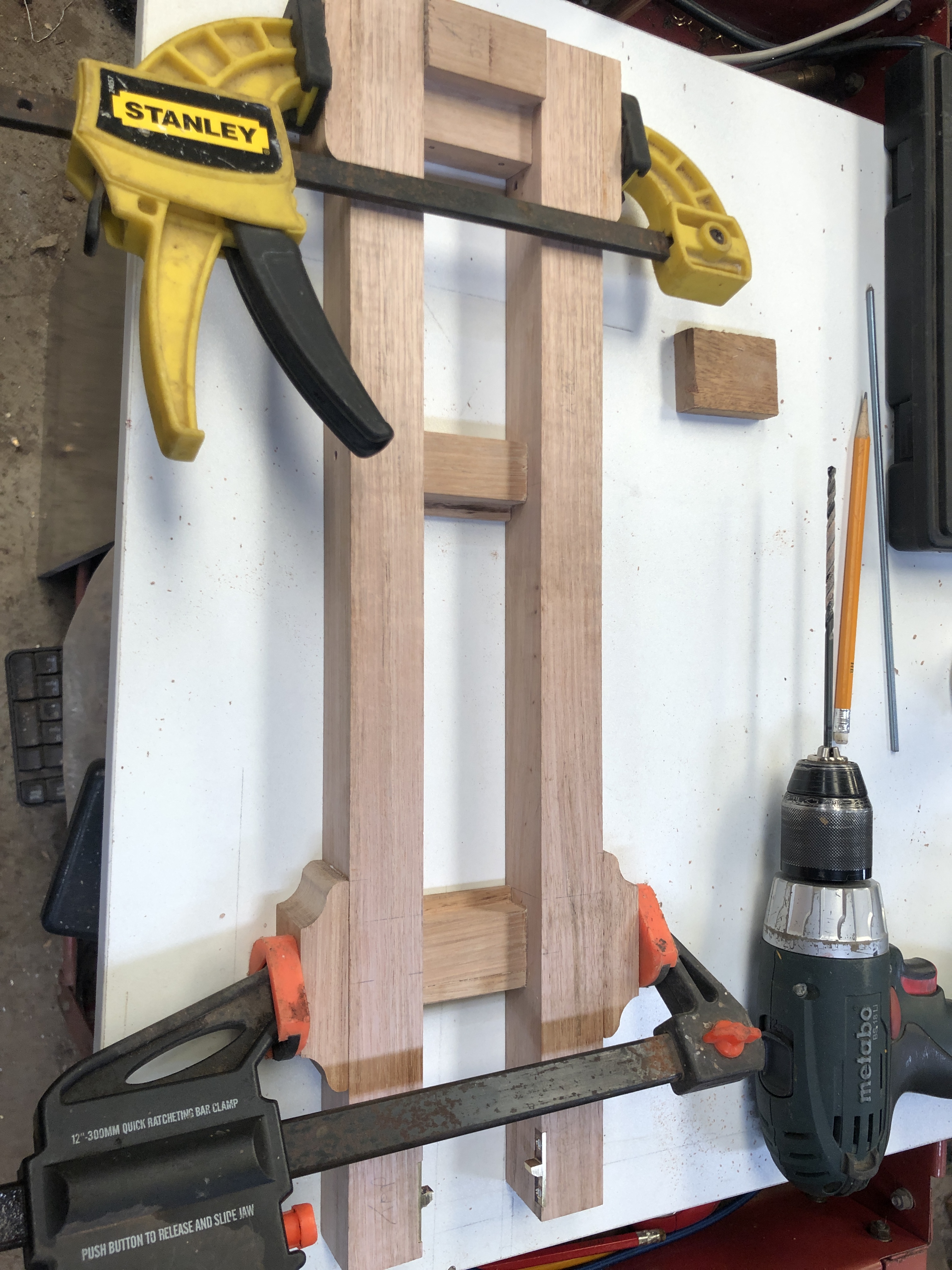
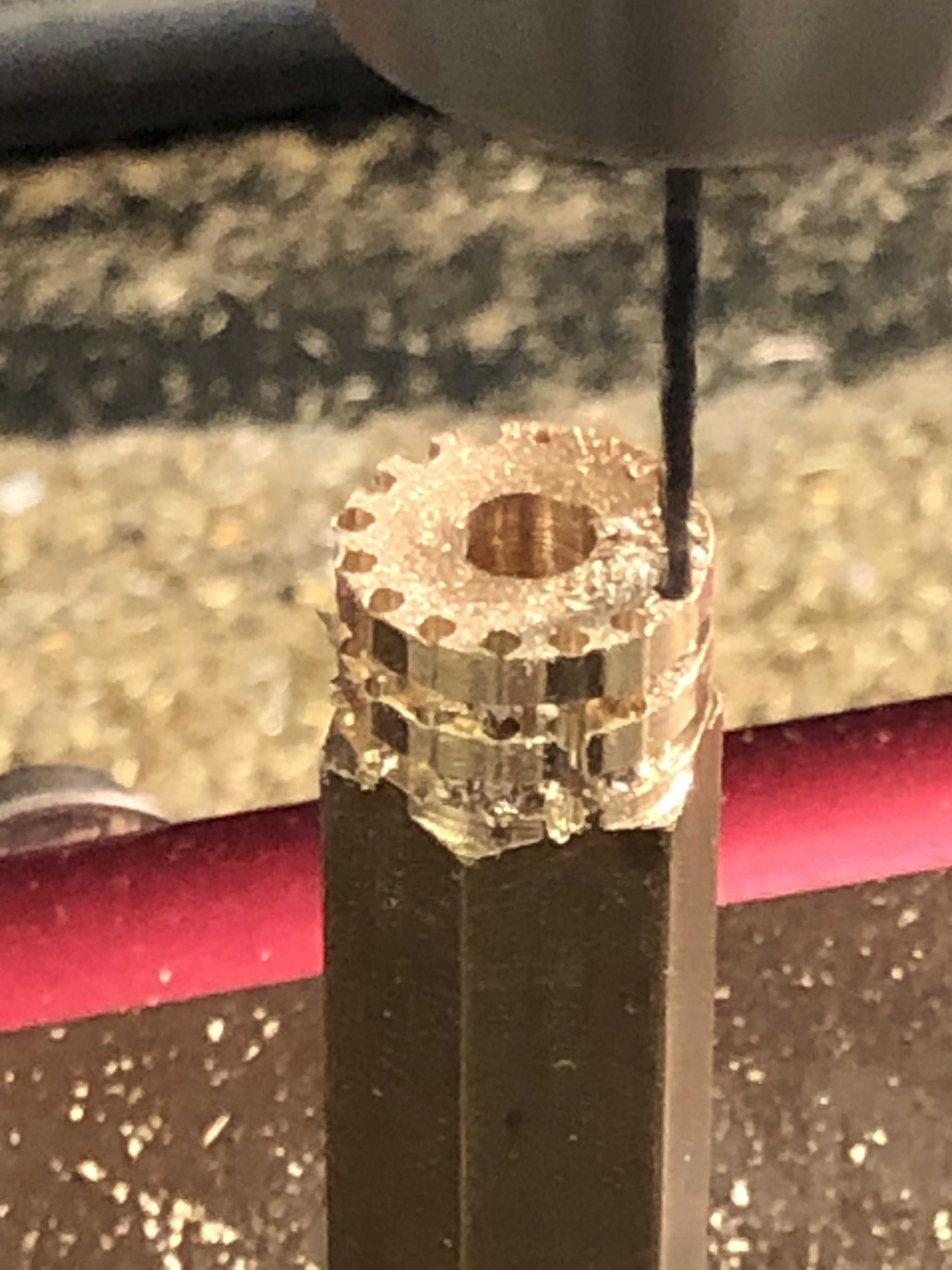
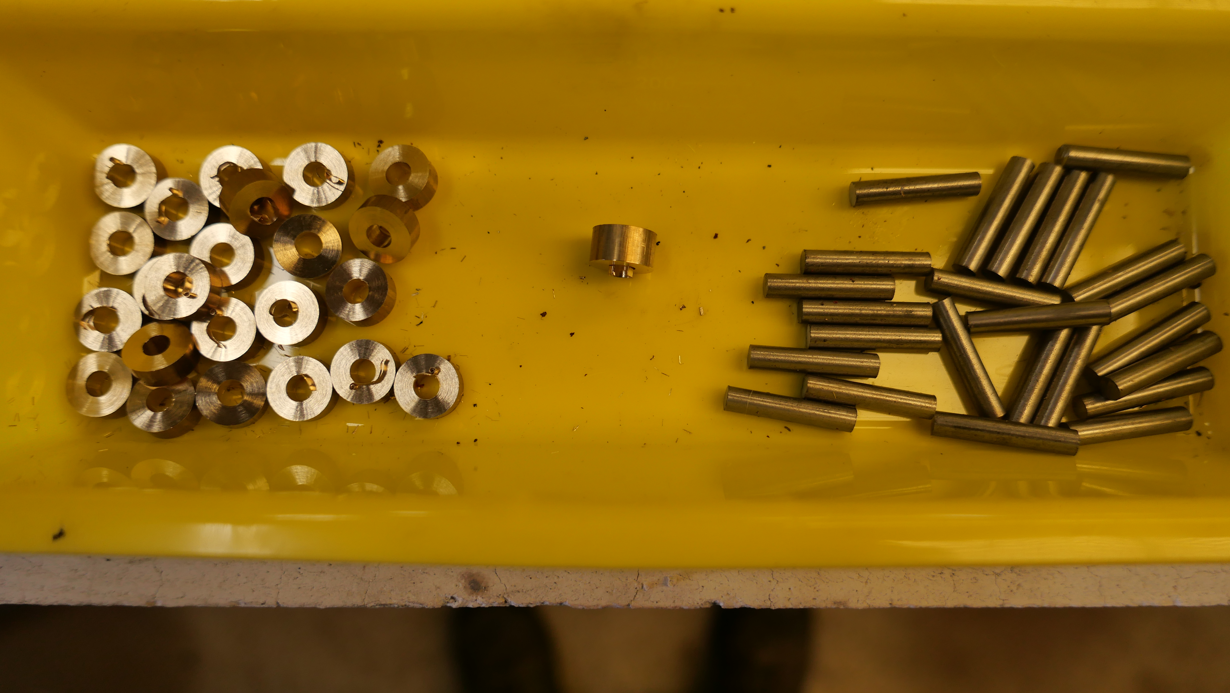
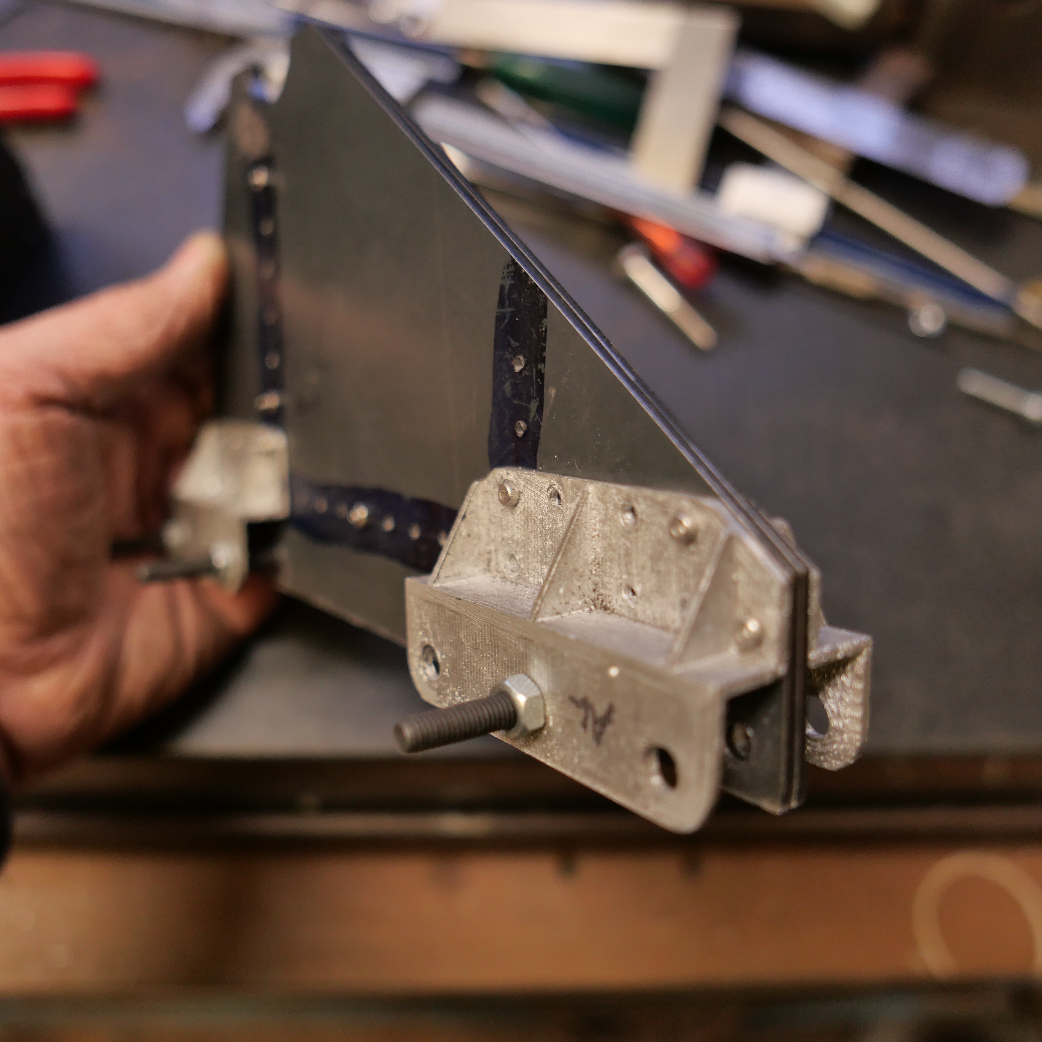
Tidied the parts with a file and belt sander.

P1074245

The brackets sitting on a photo of the original Warrnambool cannon.

The bronze bearing involved some basic lathe work.

P1074257

Then the components were silver soldered together.  Delicate work.  I did not want the solder running into some areas, and the join needed to retain a degree of precision.

P1074258

After cooling, sulphuric acid soak, and washing, the top half of the bearing was milled off.

P1074261

Some filing to make it fit the carriage, then rivet holes drilled with a Dremel while the bracket was clamped in position.

P1074264

Bolted in position temporarily.  Tomorrow I will make the top half of the bracket.  The gap between the bracket and the carriage caused by the metal folding will eventually be filled, and invisible.  A millimeter or so will be removed from the width of the bracket and bearing.

I had a bit of milling excitement while cutting out the steel components.   I was using a 6.35mm 4 flute carbide cutter, and when I started the program the machine plunged into the shape at extremely high speed.  When I checked, the feed speed was 60 times higher than I had specified.  Somehow, the units had changed from mm/minute, to mm/SECOND.  Amazingly, the cut was close to perfect with no damage to the workpiece.  But, alas, it wrecked the carbide cutter.

I had recently upgraded the CNC software (Vectric V-Carve Pro) from version 10 to 10.5.  Maybe some of my settings in the program had been changed in the upgrade?  I never use mm/second.  That is a woodworking CNC router unit.

Using a Banggood tool to make spacers

I needed 20 spacers, 2mm thick, 13mm OD, 5mm ID, to finish the carriage axles for the Armstrong model 80pounder RML.

I could have turned some 13mm OD, drilled a 5mm hole, and parted off the spacers in my lathe, but I know from experience, that the pieces never end up exactly the same thickness (in this case, 2mm thick).

So I decided to try a Banggood tool which has sat unused since I bought it many months ago.

P1074227

It is a HSS hole cutter.  18mm OD, but the disk removed is 14mm OD, just a bit bigger than I wanted.  2mm thick waste brass plate.

So I cut off 25 disks, from a piece of waste brass, 2mm thick.  The Banggood tool worked well, except that it need swarf picked out after almost every disk.   But it was quick, reasonably accurate, and the central drill bit was 5mm, just what I wanted.

P1074231

The disks were slid onto a 5mm capscrew bolt, and nutted down hard.

P1074232

The head of the capscrew was held in the lathe chuck, and the tail of the threaded end in a shop made tapered tailstock socket.  And turned to 13mm diameter. 

P1074234

About 12 spacers made per run.   Very quickly.  Reasonably accurately.  A bit of tidying to follow.

The Banggood tool worked pretty well.  I will buy some more of these.  They were quite inexpensive.

Today I polished the ends of the trunnions, being careful not to remove the lasered lines and markings.  I used a 200grit sanding pad in a sponge backed sanding disk in my milling machine.   Also worked very well.  I removed about 0.1mm of steel, without destroying the markings.

P1074221

Axles for a Cannon Carriage

How fascinating is that for a topic!

Well, I found it interesting.  Maybe says something about me.

My 2 carriages have 20 wheels and 20 axles between them.  Plus the 4 big ones under the chassis’.  I had made the wheels.  The axles required some planning and thought, after all, whatever I did was going to be repeated at least 20 times.

I decided on stainless steel for the axles, and brass for the end caps.  The originals were steel, but they will be painted, so the appearance of the metal is irrelevant.

First steps were to cut up 20 pieces of 5mm stainless steel, 25mm long, and drill 5mm holes in 12.7mm brass rod, and part off 20 pieces 5mm wide.  With a few spares.

P1074196

The the brass end caps need to finish 4mm wide, so there was a machining allowance of only 0.5mm on each face.  So the silver soldering of the 2 parts needed to be reasonably precise.

P1074197

To assist with keeping the brass disks square to the rods while soldering, I drilled some 5mm holes in an aerated concrete block, exactly 21mm deep.

P1074198

Fluxed the mating parts, and silver soldered 5 at a time.  Very quickly.  I could have used Loctite 620, but would have had to wait until it cured before machining.

P1074200

A soak in sulphuric acid for a few minutes, then a water rinse.

P1074202

Then turned the end cap shape on the Boxford TCL125

P1074204

P1074206


Not quite finished. M2 Holes to be drilled through the end caps, and threaded to the brackets.  I will use the CNC toolpost milling attachment which I made in 2019.  That might warrant a short video.

A short video.  Well, a bit over 5 minutes…


P1074217

The capscrews are not kosher.  The original cannons had large slot screws.  But will anyone notice?  (idea…  I could fill in the hex hole with JB Weld, and machine a slot?!).  Maybe.

In retrospect I could have done the entire shaping and drilling and milling of the brass end cap using the toolpost mill on the CNC lathe.   Would have been a lot more efficient.

Recovering from Friction Welding

Back to the model Armstrong cannon carriage this afternoon, and fitting 2 internal transoms, which provide rigidity to the carriage.

The transoms had been laser cut some months ago.  I cut the floor from 2.8mm stainless steel.

Each transom is attached to the sides and floor by angle iron, 2mm thick.  In the original cannons the angle iron was mitred at the corners, and for this model “A” carriage I decided to try to replicate the mitres.

The angle iron was again bandsawn from RSS tube and milled to 10x10mm.  I used the following setup to form the 45º angles…

P1074188

This is the Eccentric Engineering tool sharpening arm, set up to 45º on my RadiusMaster belt sander, about to form mitre angles on the angle iron resting to the right.

P1074193

The Angle iron pieces were glued to their respective transoms, and 2mm holes drilled.  Bolts progressively inserted.  The lengths and cutouts will be trimmed later.

P1074195

Then milled and filed the corners until the parts fitted neatly into the carriage.  Rivets will be inserted later.


…and for your interest/amusement, depending on your UFO opinion…  Listen to the information, and try to ignore the appearance of the narrator.


….and do I think that UFO’s are real?    I would say that my “belief” has risen from 95% to 99% YES.   One of my readers, with whom I have spoken directly, and for whom I have no doubts about personal veracity, has seen one at close quarters.  Do I think that they are of non human origin?  A bit less positive about that one, but it does seem more likely than not.  Waiting to see if and what NYT does publish.


Friction Welding

Friction welding is a technique which is used in industry.  It involves rotating 2 metal surfaces against each other, under considerable pressure.  The heat generated from the friction is enough to make the contact surfaces to become red hot, then melt together.   There is a funny and instructive YouTube video on the subject by AVE.

I had a costly and unintended demonstration of friction welding in my workshop yesterday.  I was drilling multiple small holes in the 2mm thick sides of the model Armstrong cannon, when, somehow, I activated the Z axis downward in fast motion.  Probably I miskeyed G0 instead of G1.

The hole was drilled in a fraction of a second and the chuck continued downward.  My reflexes are not TOO bad, but by the time I hit the big red button, the bottom of the drill chuck was grinding into and bending the workpiece.  Which was glowing red hot!

“Oh Dear”! (Or something along those lines.)

I could tell at a glance that the workpiece had been destroyed.  I had a spare piece, so it was going to cost some time to repeat the work already spent on the part, probably at least a day.

But that was only the beginning.

I backed off the quill, and tried to remove the workpiece from the of the chuck.  It would not budge, so I released the 2mm drill bit (actually a carbide end mill) from the chuck.   Well, I tried, but the chuck key would not rotate.  The chuck was frozen solid.  So I went and had a cup of coffee.

On return, it was apparent that the workpiece was welded to the end of the chuck, and the chuck jaws were welded together at the tips.

So, I released the chuck and its arbor from the mill, and broke off the workpiece from the chuck with a hammer.  The weld and the drill bit broke.  But the jaws of the chuck were still welded together.

You might recall that I had accidentally destroyed an expensive Japanese chuck some months back, and this one was its “temporary” replacement.  Obviously I will need to buy a replacement this time, but I am in the middle of my cannon build, and want to get on with it.  What to do?

On close inspection the weld between the jaws stopped about 3mm from the jaw tips.  It involved the surfaces between the jaws and the still present carbide drill shank, and the sides of the jaws.   So I ground about 3mm off the ends the jaws until they started to move.  Then used a tiny grinding wheel in my Dremel to remove most of the weld between the sides of the jaws.   At this stage the chuck is looking very ugly, but it works in a fashion, and I was able to resume my drilling.   Very carefully.

I did straighten the bent workpiece, but it is RS.  I spent the remainder of the day using my spare workpiece, repeating the lost work.    No photos of the damage.  I was not in the mood.

P1074187

These are the sides of the second carriage.  For this one I am drilling the holes in both pieces simultaneously, by clamping, and then bolting them together.   Pretty obviously a better method.  Sometimes I am slow learner.  But I do try to not make the same mistake more than 3 times in a row.

P1074185

The “B” carriage on the left, and work to date on the “A” carriage on the right.  The bolts will eventually be replaced with rivets.

BTW,  I have de-monetised this blog.  You should not see any more advertisements.  I noted that the income from the ads from the one post on which they appeared, was one cent.  Yep.  One cent.  If I had monetised the site from its beginning, 6 years ago, I would have earned approximately $AUD6 dollars.  Nuf said.

Meanwhile, I discovered some more videos from posts 5-6 years ago.  I have deleted the videos.    A pity about that, but it has created some more storage space and allows me to continue to post on the current plan.

Carriage Assembly, and Gun Spiking.

If you have been following the build of the model Armstrong cannon, you might remember that most of the steel panels for the carriage were laser cut a few months ago. In the past few days I have been drilling dozens of 2mm holes, ready for final riveting.  Meanwhile the parts are held together with 2mm bolts and nuts.  I expect that the rivets will not be installed until I can see that everything fits and works as it should.

P1074175

Only a few fasteners so far, but it is surprisingly rigid.

P1074182

P1074183

The angle iron is cut from the corners of rectangular section tube with 2mm wall thickness.  It does require some more finishing and rounding off, but the scale is accurate.  The big hole is to allow the hydraulic recoil tube to be inserted.  The recoil cylinder will be 18mm diameter.

SWMBO’s comment….  “It looks like it is made from Meccano”.  I guess that there are a lot of holes.

Meanwhile I have discovered an excellent reference source, published in 1879.  It is a free book, available online at Google Books.  “Treatise on the Construction and Manufacture of Ordnance in the British Service”.  517 pages.  Original price 9 shillings.  It is full of gems for the cannon modeller.  As an example, this is a drawing of the sights on the 64 pounder RML converted to 80 pounder.  You will see that the barrel shape is different from the one which I am modelling, which is a mark 3.  But it is probable that the sights remained the same as those pictured.  A great find, with enough detail for me to scale down and model.

Screen Shot 2020-07-19 at 12.18.03 am

Note that the sight on the right is not vertical, but sloped at approximately 2º.  That is to compensate for the slight deflection of the projectile to the right, caused by the rifling.

Screen Shot 2020-07-19 at 12.07.37 am

From the same book, a detailed description of the Vent / touch hole / ignition hole.  It was NOT just a simple hole drilled into the barrel, but a copper cylinder which was threaded into the barrel.  The touch hole was drilled through the copper.  The reason for this was that the touch hole gradually became bigger with use, and needed replacement after a certain number of firings.  It also allowed repair of the touch hole if the gun was “spiked” by the opposition, but that was a major exercise which required specialist knowledge and tools, and a return to the factory or one of the 5 workshops listed above.

Armstrong Cannon Chassis Wheels

The assembly of my Armstrong cannon is progressing more slowly than I anticipated.  No excuses.  Just lots of holes to drill in precise positions, parts to turn and mill.  And my workshop sessions have become shorter in the winter cold.   Not that I mind the cold.  I just light my workshop wood fire to remove the chill.

Today I have been making the wheels for the chassis.


PANA4079

Not a great photo. It shows a front wheel, 33mm diameter, turned from stainless steel. No axle yet.

PANA4080

And a rear wheel, 50mm diameter.   Yet to have the track groove turned into the periphery.

PANA4077

I thought that the wheels would be easy to make.  Just a bit of basic turning to size and form turning for the track groove and decorative relief on the faces.  But as usual, I used whatever material I had on hand in the size.  In this case stainless steel.  It looks great when turned, but does work harden quickly, causing tooling problems.  Parting off, through 50mm of hardened stainless steel is not much fun.  In the end I used the band saw for parting, then tidied up the ends on the lathe.


Model Armstrong Gun Cypher

Yesterday I spent some time with 600 grit emery paper on the barrel.  A bit more elbow grease is required, but I took some pics of the progress….

PANA4062

From the left, the sighting line called the “line of metal”.  There will be a corresponding line on the muzzle.  Next is the weight of the barrel in hundredweight.  81cwt = 4 imperial tons plus one cwt plus 2/4ths of a cwt plus zero pounds.  One hundredweight = 112 lbs, so this barrel weighs 9128lb / 4140kg.   The arrows indicate that the barrel has been “proofed” and accepted for service and also possibly mark the end of bore.  The dot would be where the “vent” would be located (the ignition or touch hole) usually about half way along the powder cartridge.  Then the reigning monarch’s cypher.  In this case, Queen Victoria, with her motto, that of the Order of the Garter.  HONI SOIT QUI MAL Y PENSE.  The translation from French is  “Shame to him who thinks ill of it” (“it” being the Order of the Garter)

PANA4063

The Royal Gun Factory number of this barrel, and axis lines.  One reference stated that they mark the centre of gravity of the barrel, but according to my assessment, the COG is well behind this point.

The other trunnion marks are yet to be lasered.  Maybe late next week.

I am delighted with the quality of the laser “engraving”.  It is sharp, crisp and finely detailed.  Again, thanks to Stuart Tankard for the use of his laser, and for operating it.