Boiler Certification
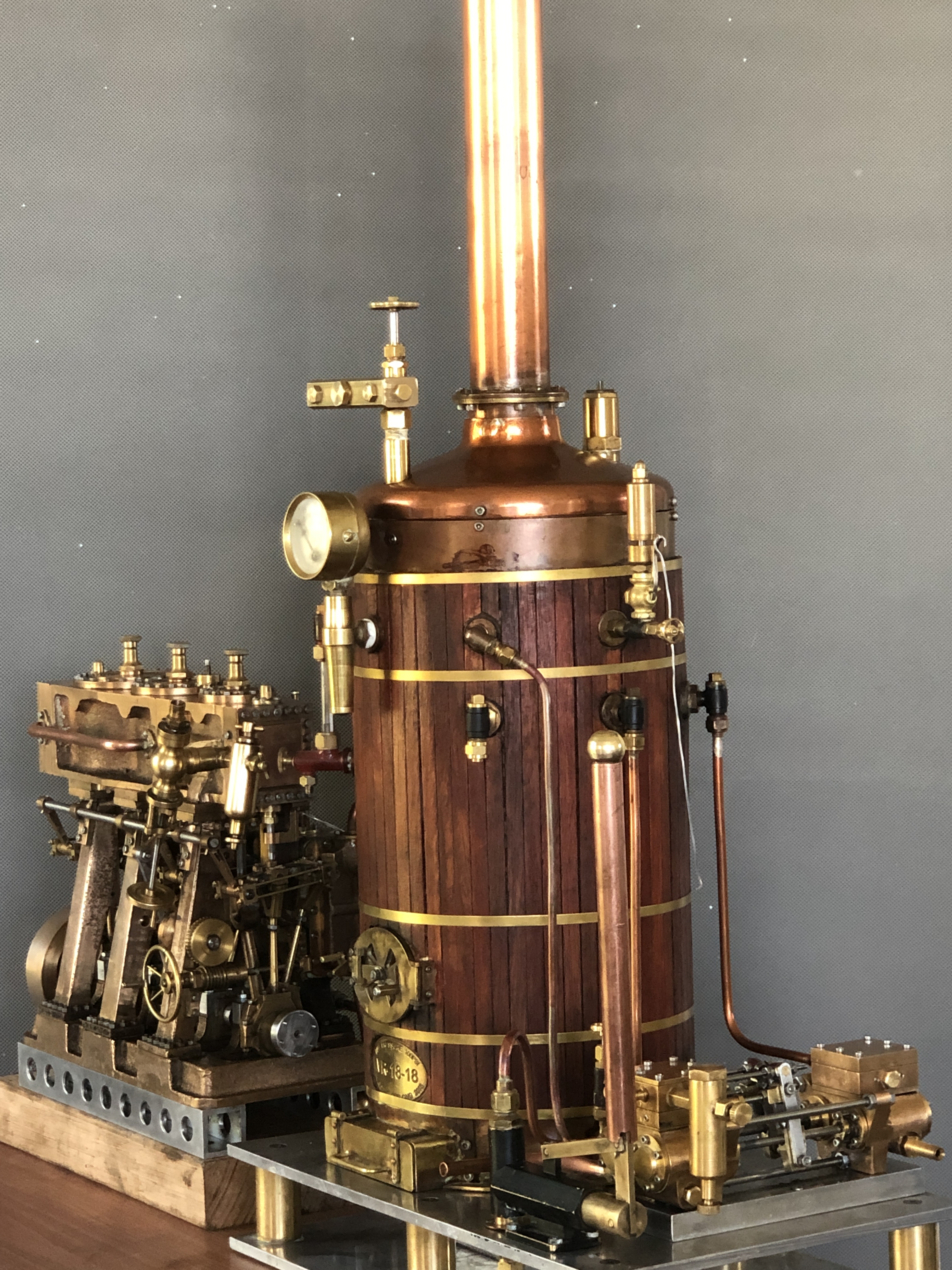
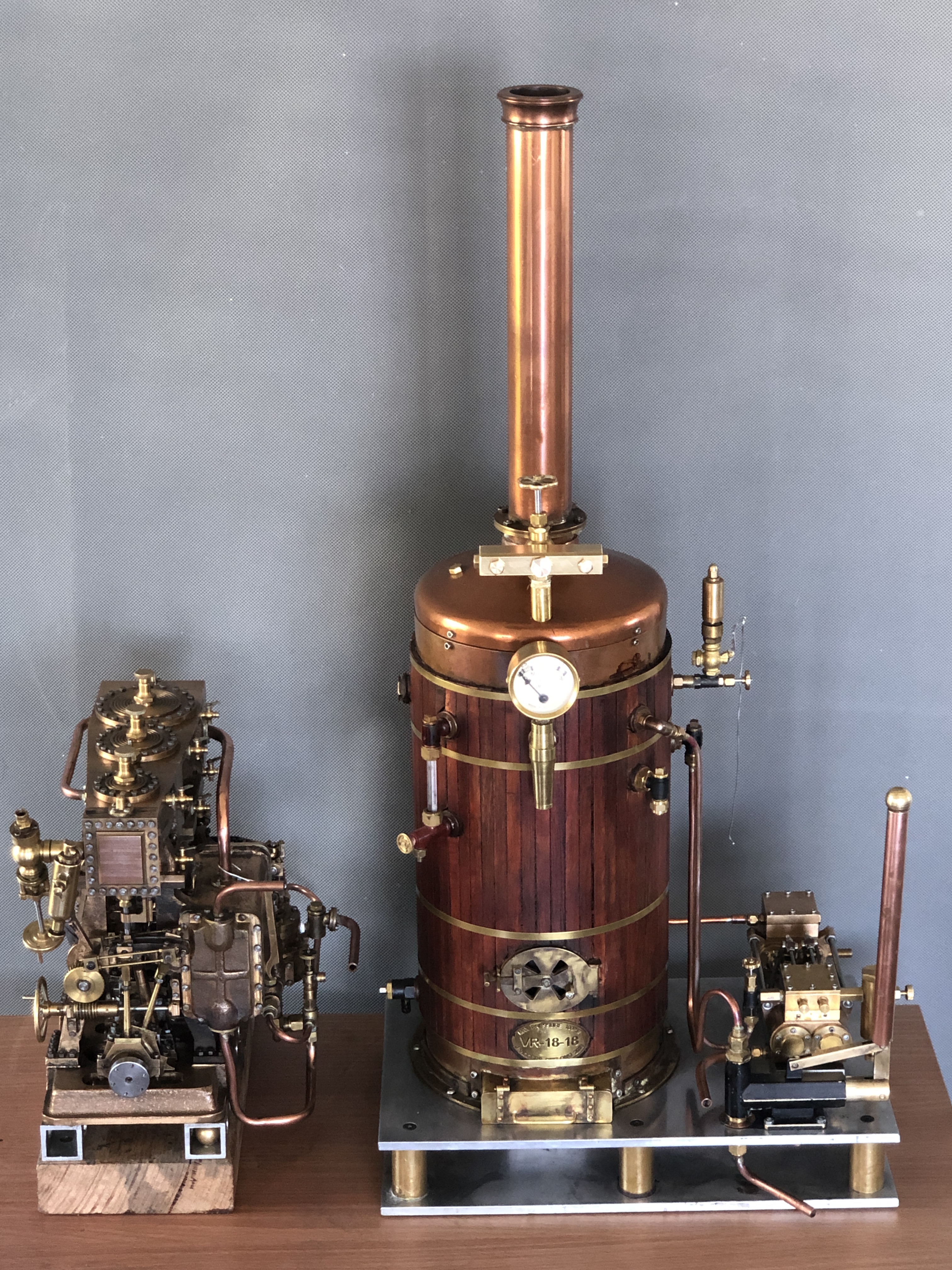
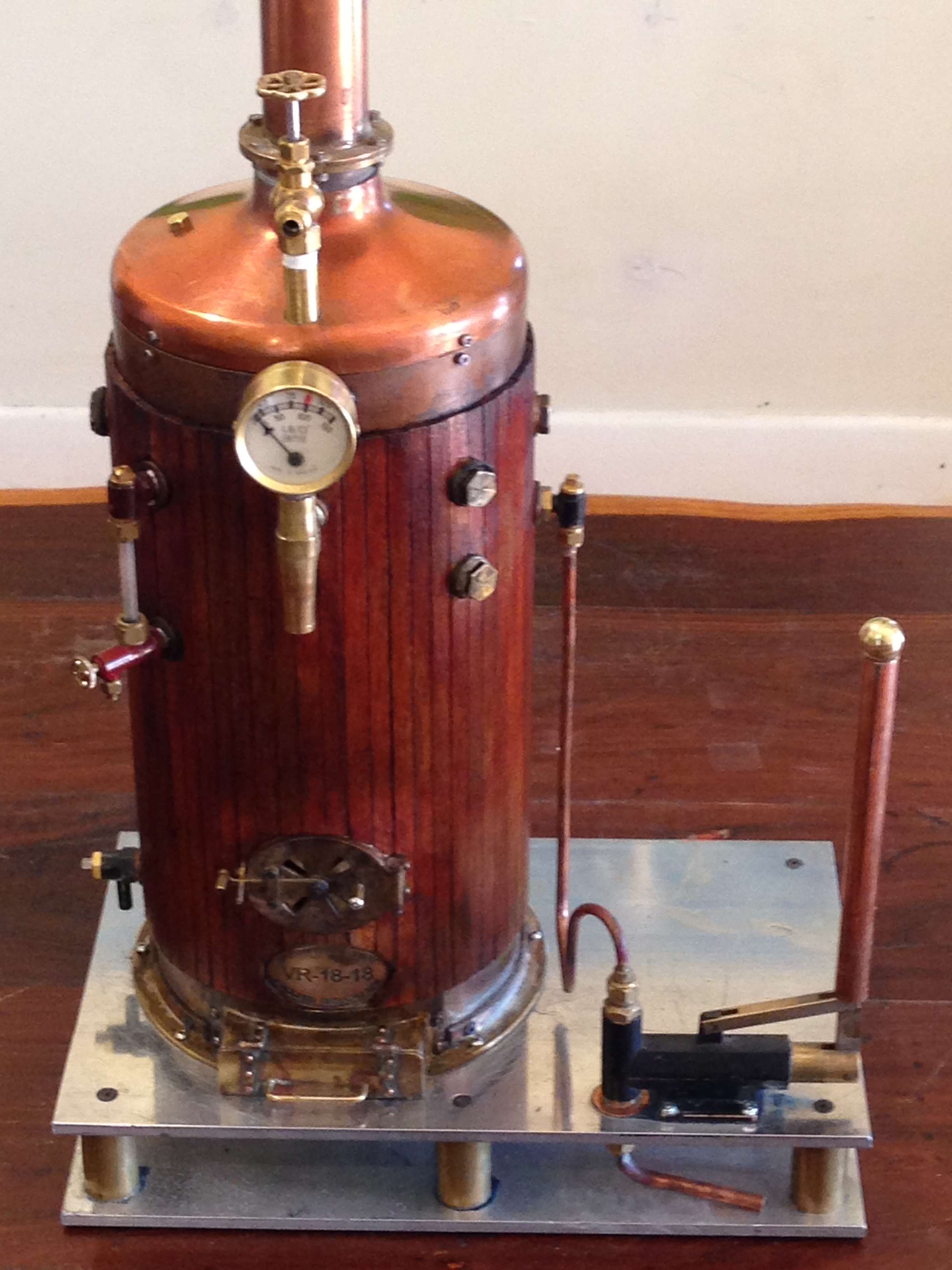
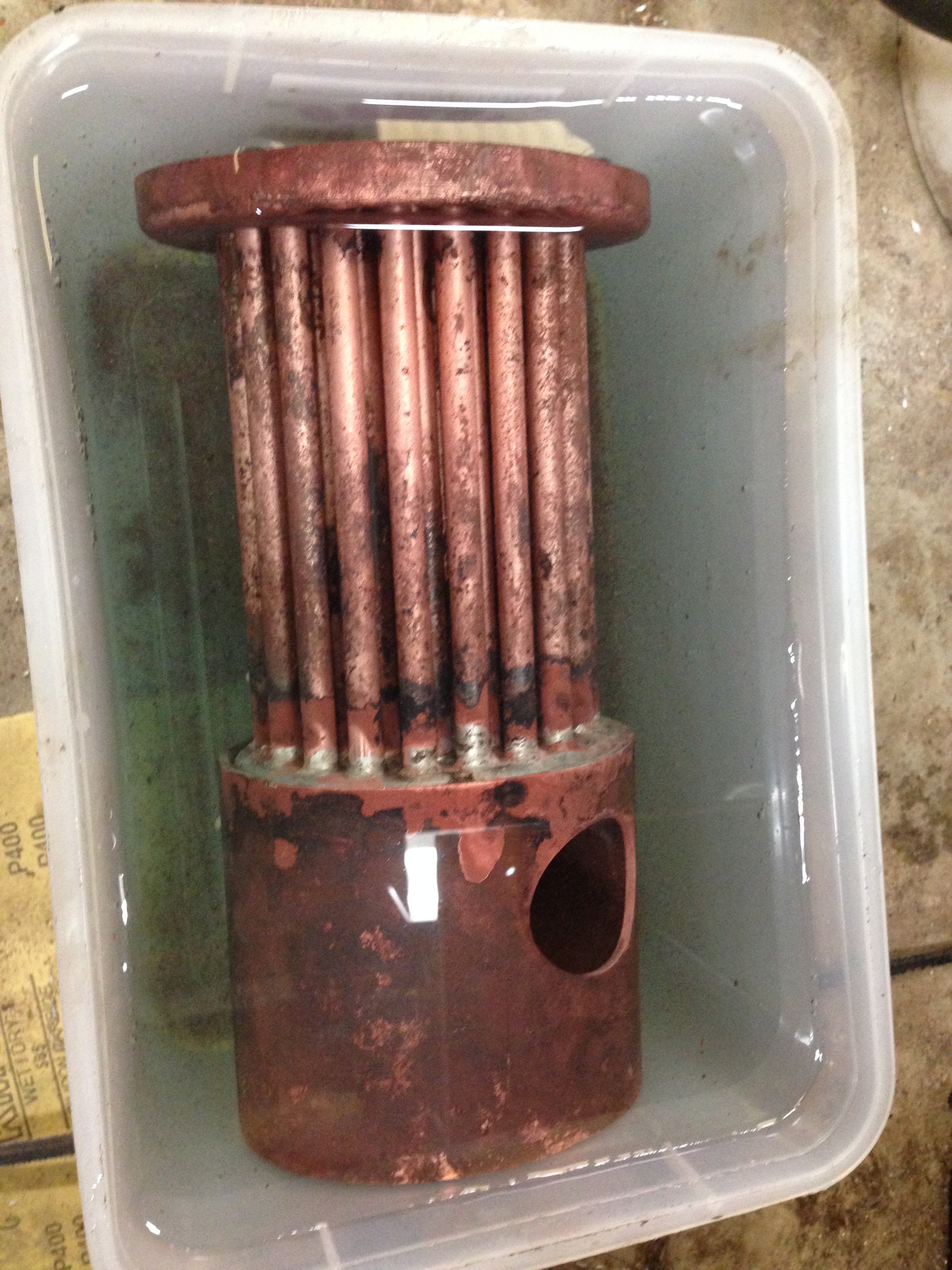
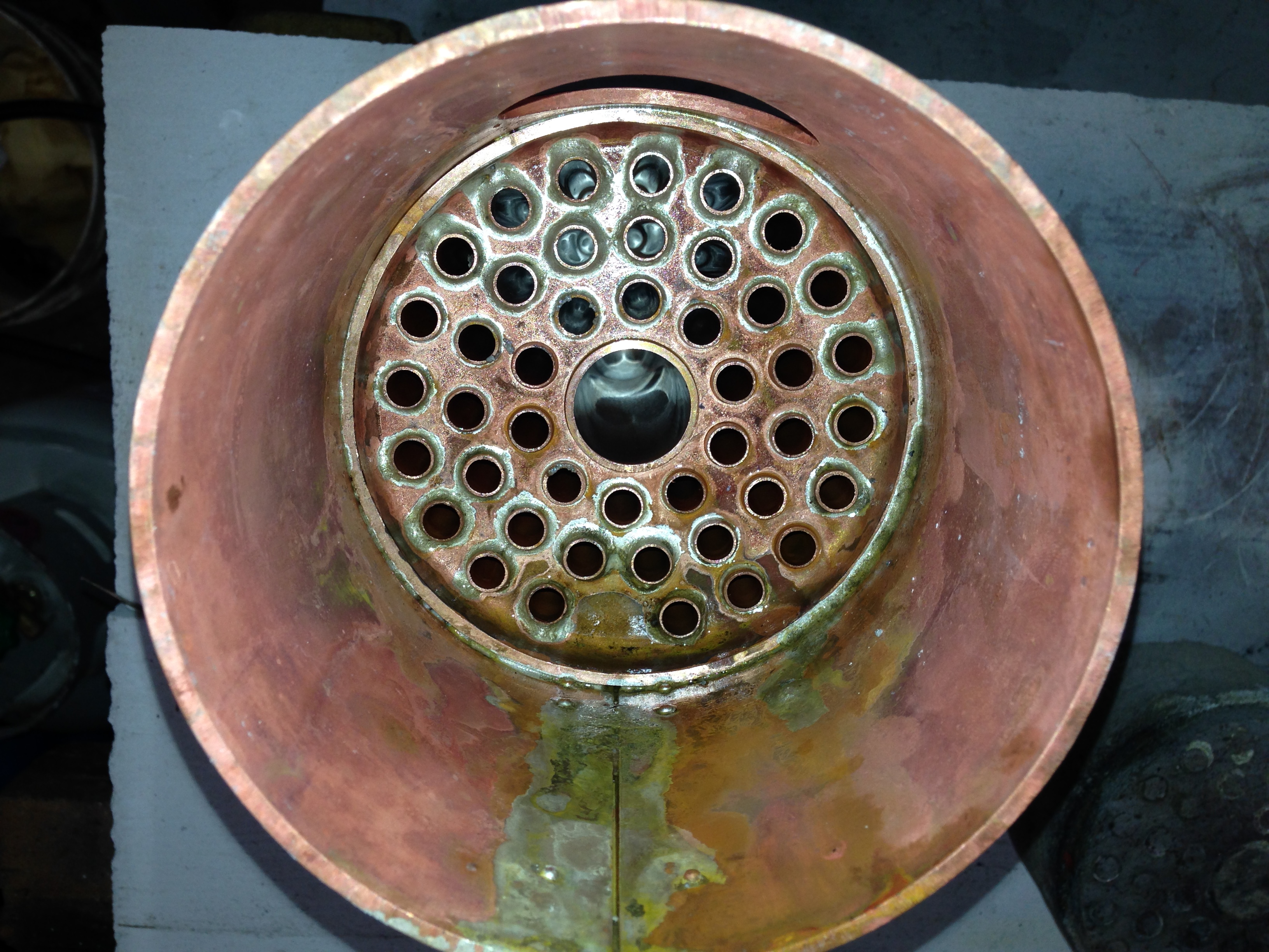
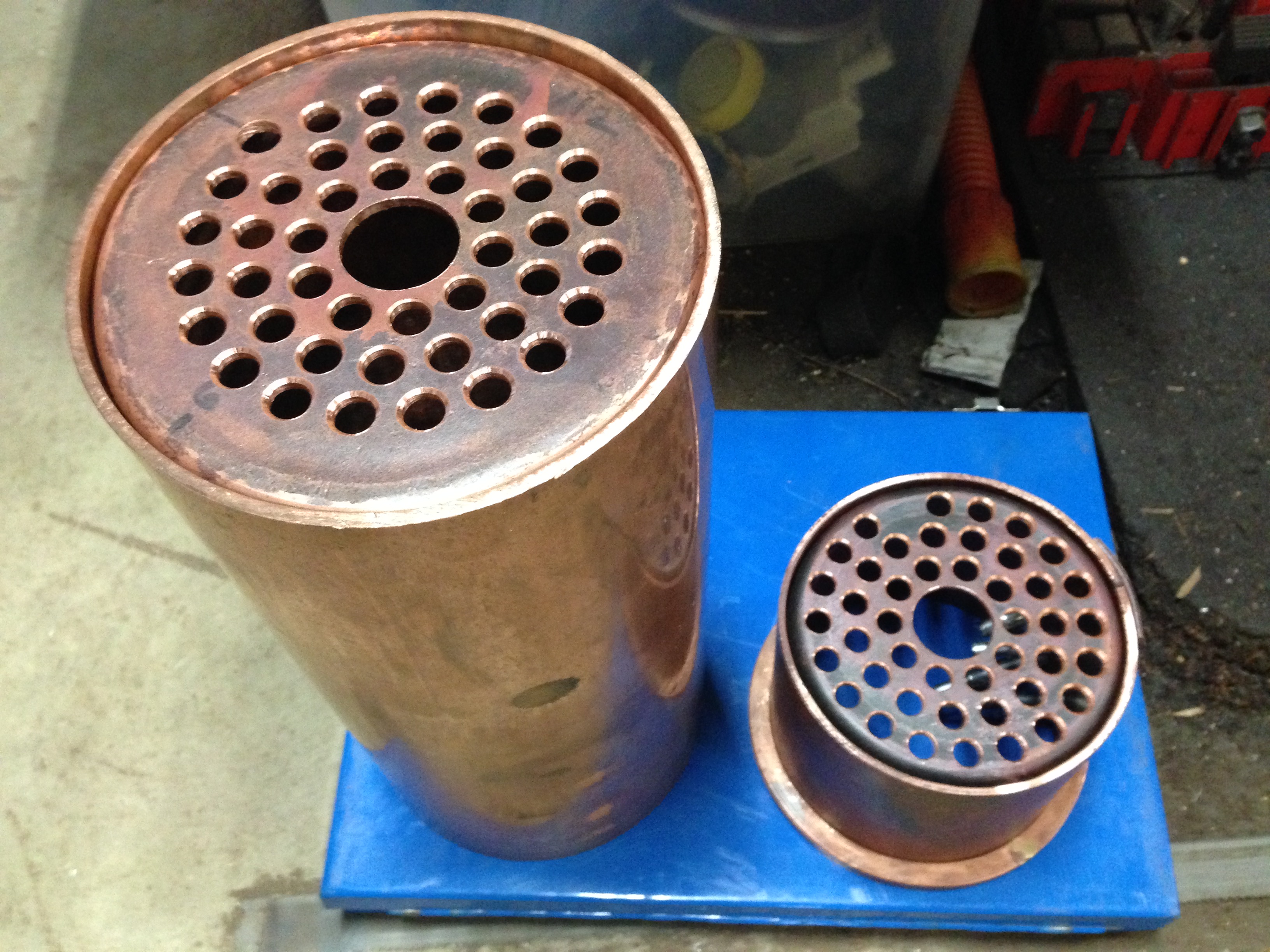
Well, actually it was a re-certification, for 3 boilers. The 1:4 traction engine has a 7″ diameter boiler, with a maximum pressure of 100 psi. and is coal-wood fired. The vertical test boiler is 6″ diameter, rated to 100 psi, and is gas fired. And the Trevithick dredger engine at 1:8 scale, is rated to 40 psi. Although it was designed to be fired with coal or wood, it is also gas fired. Mostly at exhibitions it uses steam produced by an external boiler, but the boiler in the model engine acts as a receiver for the external steam, so it also has to be certified to be run in public.
During the years of the Covid lockdowns none of these boilers were used much, and they were all out of certification. So with life returning slowly to normal, and exhibitions planned for 2023, I contacted our club’s boiler inspector, and arrangements were made. Since there were 3 boilers involved, and 2 other members of our club wished to speak to the inspector about their current builds, he offered to come to Geelong, which was incredibly helpful.
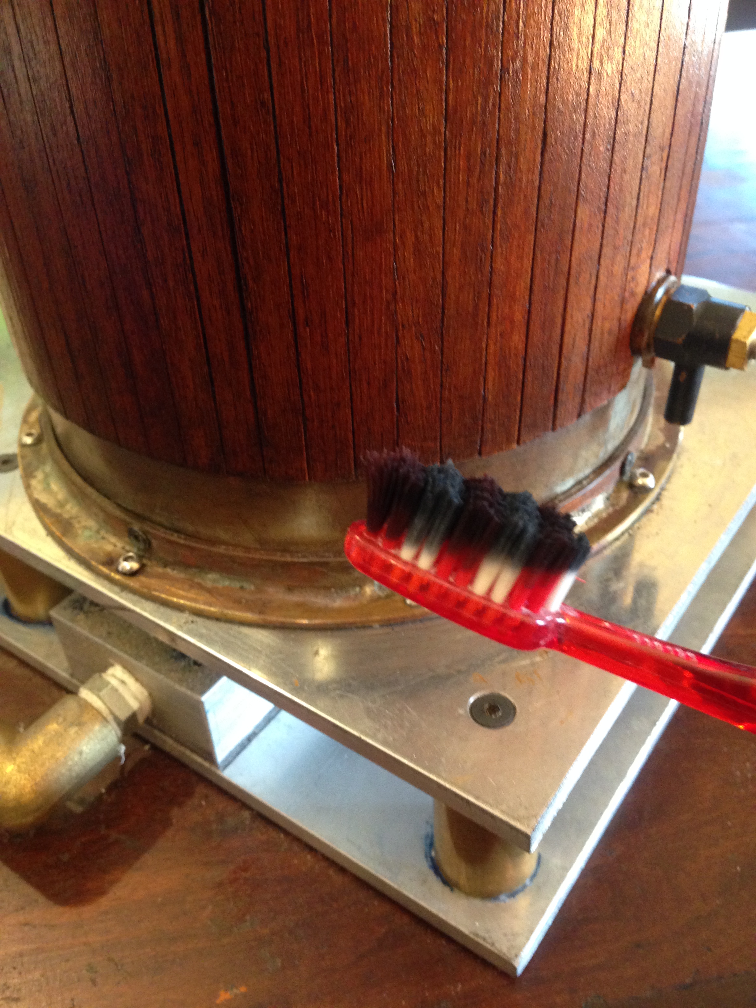
As preparation for the inspection I ran each boiler to make sure that all was in order.
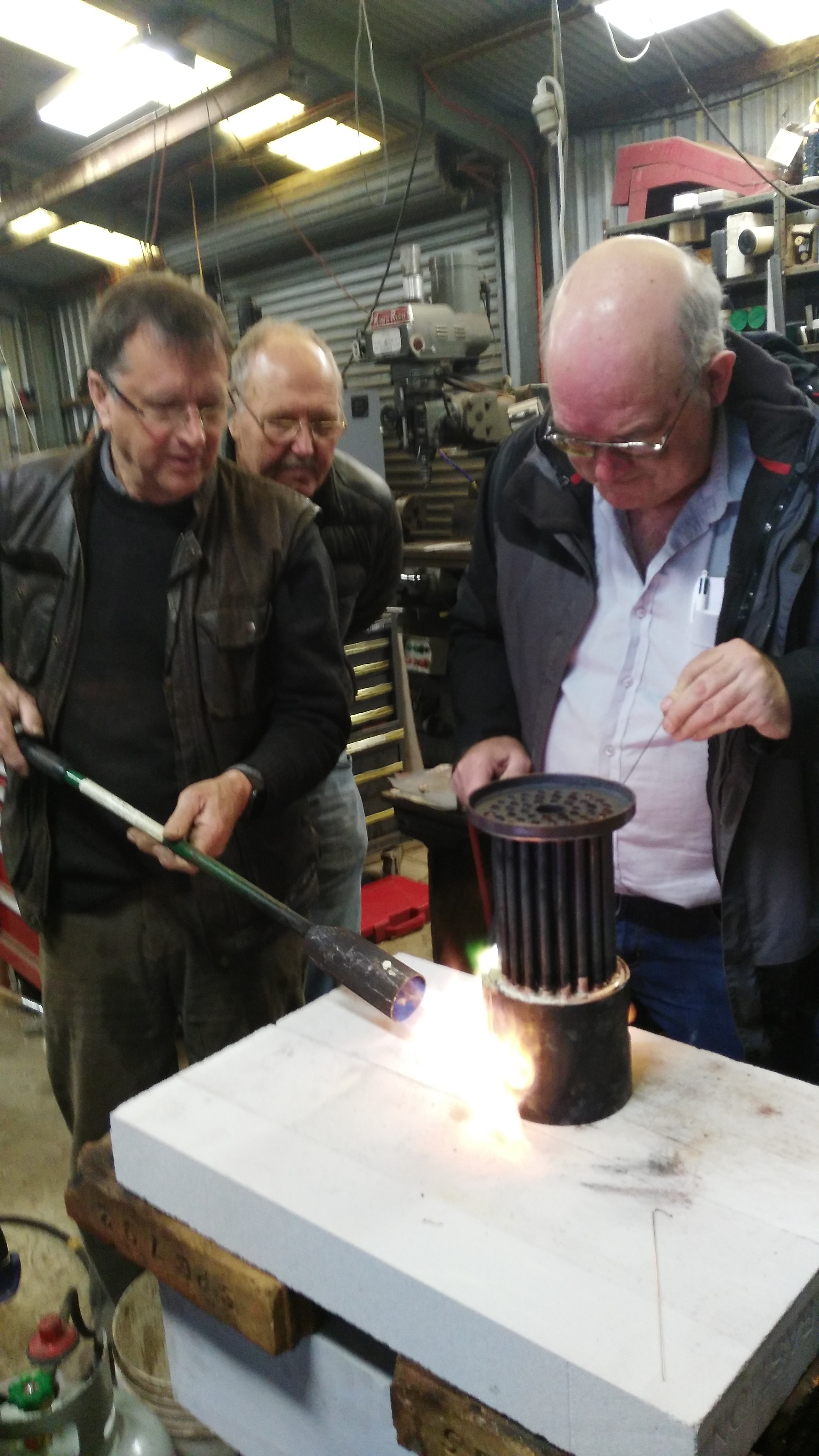
I have previously described the problems found with the traction engine. Various water and steam leaks were fixed, and the crankshaft repaired, although a more permanent crankshaft replacement is underway. The boiler inspector was really only concerned with the boiler itself, the water pumps, the sight gauge, and the safety valves. Two actual tests were performed. The boiler was filled with water, then the hand pump was used to hold the pressure at 20% above working pressure i.e. approx 125 psi. The boiler was checked for leaks and distortions. Not surprisingly none were found. Then the water level was drained to normal, the fire was lit, and steam pressure increased to 100 psi. The fire was encouraged to burn as fiercely as possible, using the funnel blower, and later the steam blower. That was to make sure that the safety valves were functioning adequately, and at the correct pressure.
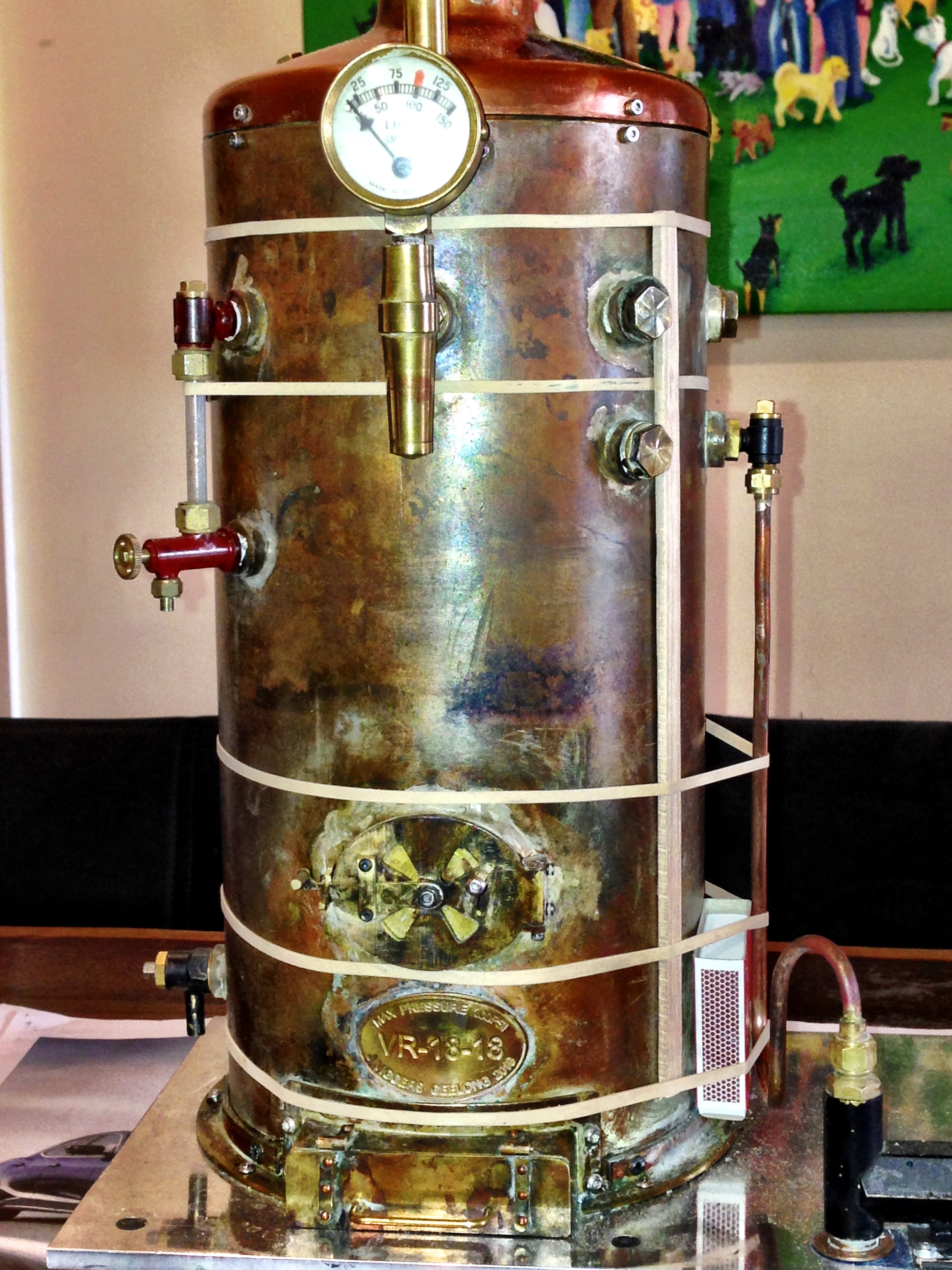
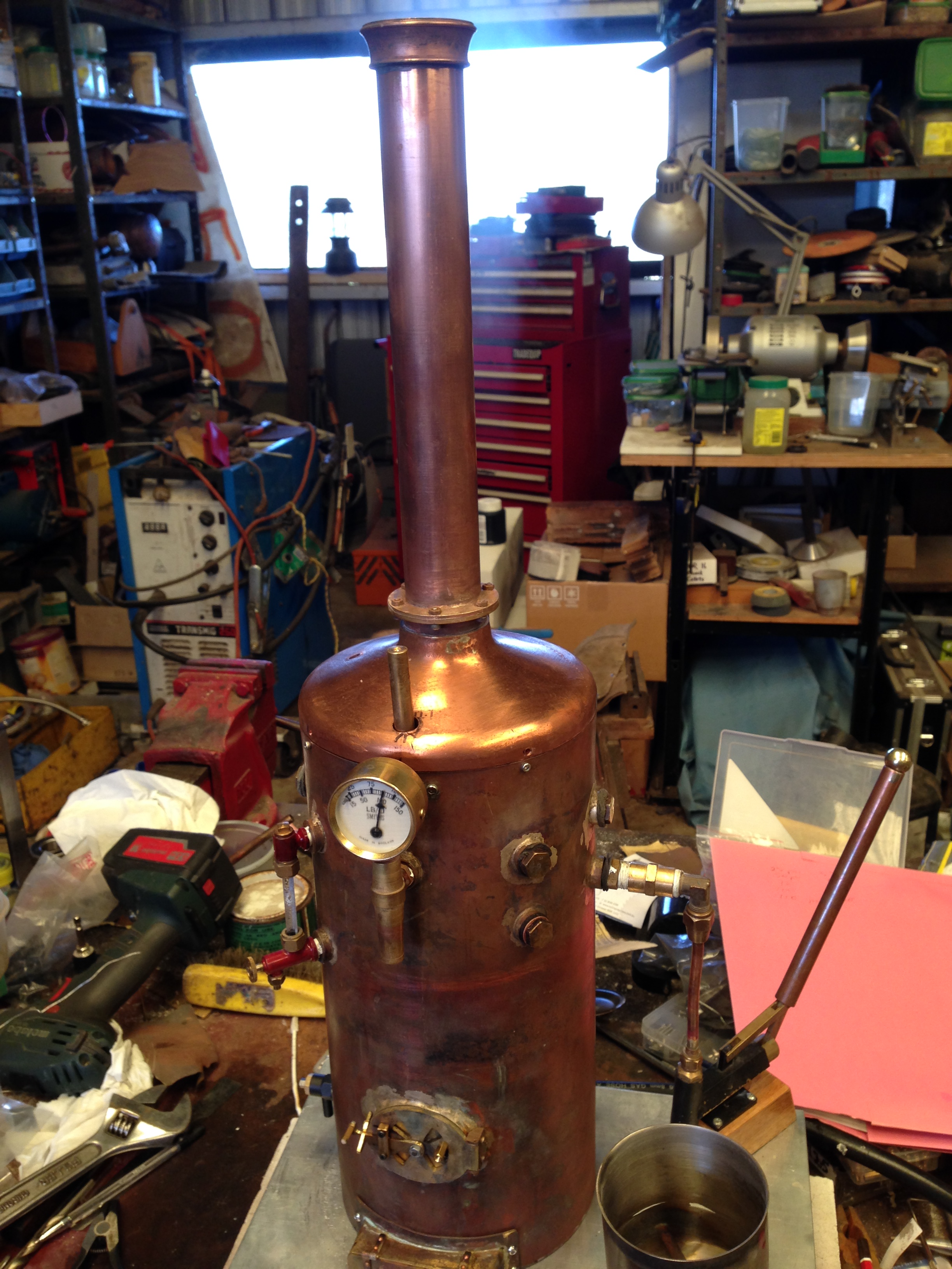
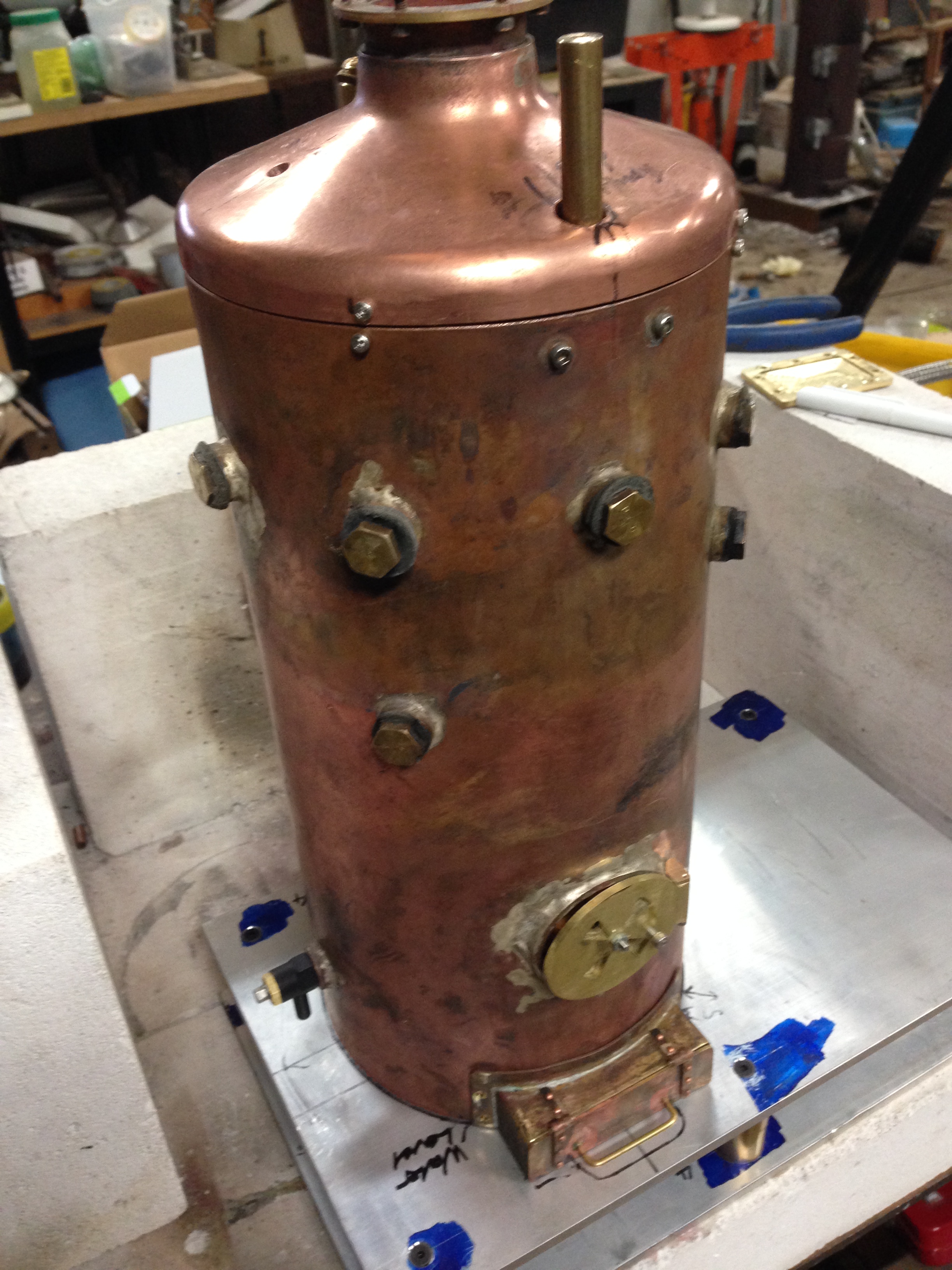
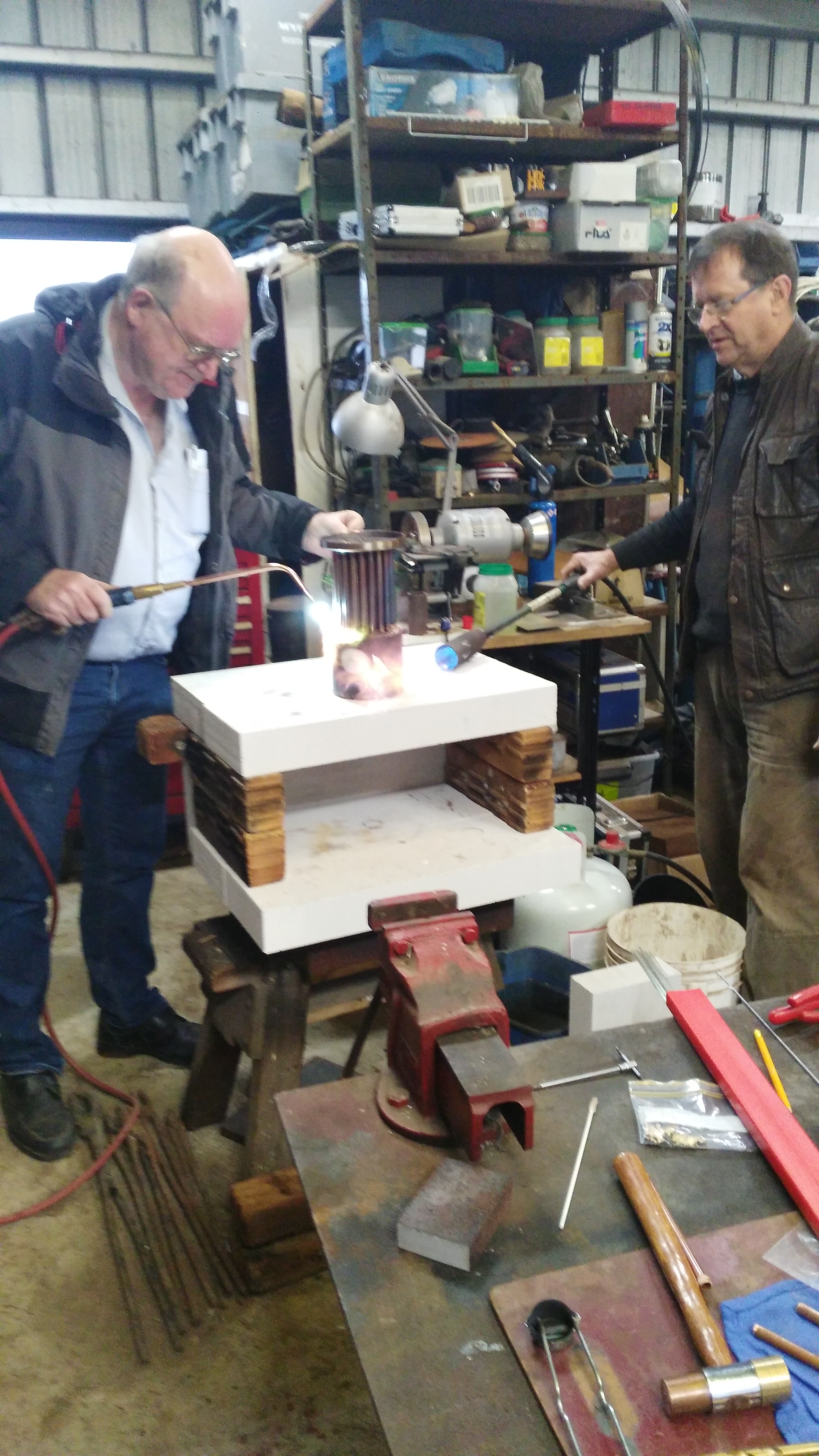
Then the vertical test boiler underwent the same procedures, but with a gas burner.
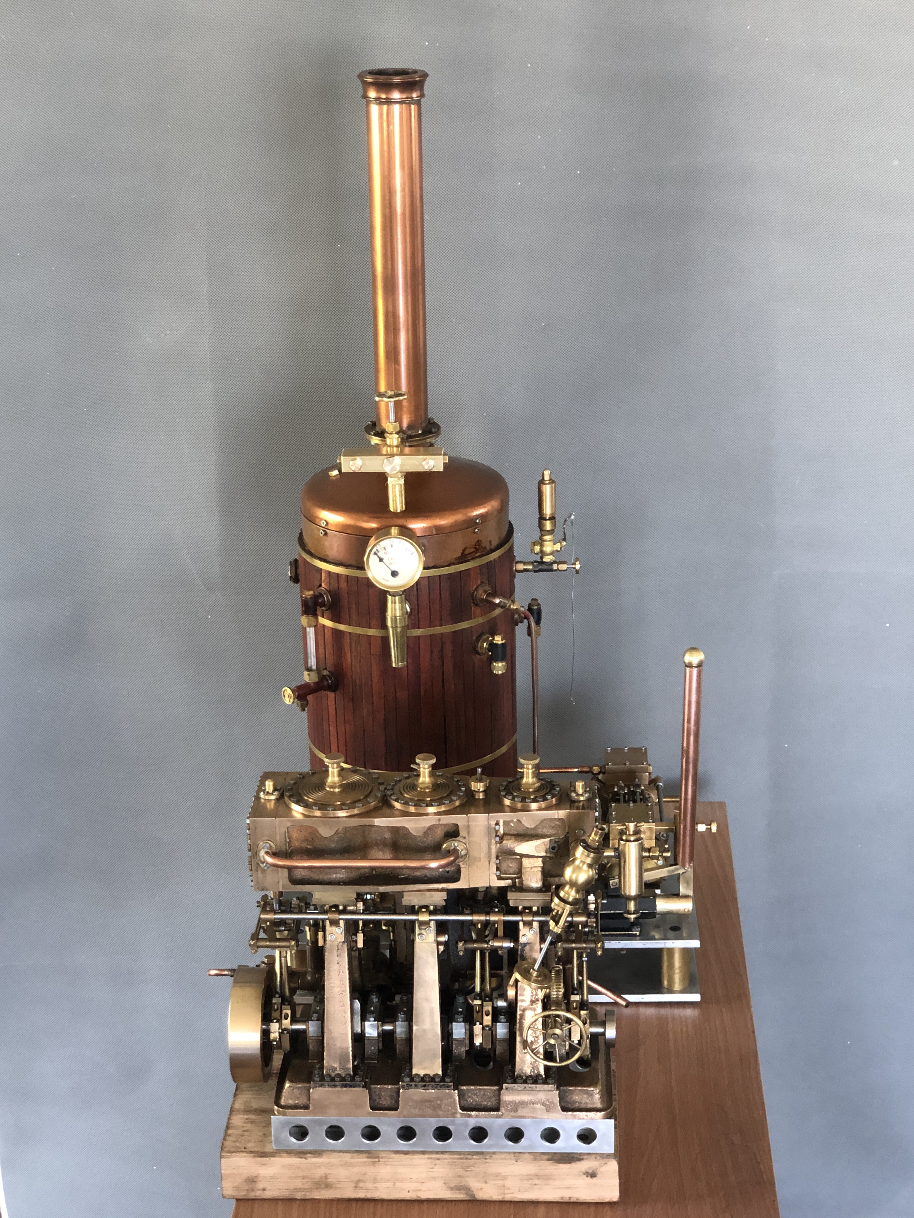
And the same for the Trevithick dredger engine, also with a gas burner.
All of the boilers passed the tests, and certificates were issued, for 4 years. Phew!
However, the big issue, the Elephant In The Room, is that the rules for small steam powered engines, trains, traction engines, which are fueled by gas have changed. In future all gas fittings have to be installed by licensed gas fitters. All gas fittings have to be purchased, approved and stamped, not made by the model maker. And currently, NO gas fitters in Victoria, and possibly any other Australian state, have been willing to be involved with engines, trains etc. which have been made by model engineers. Even installing gas burners which are sold for barbeques, camp stoves etc will not be permitted to be used in public exhibitions of steam engines, locomotives etc.
Which means that no gas fired model steam engines will be able to be run in public. It remains to be determined what the situation will be with gas fired internal combustion engines.
It should be stated that the new rules are under intense scrutiny and discussion. There is some hope that common sense and sanity will be applied. Or the current nanny state, Occupational Health and Safety nonsense will be applied to its fullest extent of stupidity. We can only hope that this will not be the end of a fascinating, stimulating, entertaining, and educational hobby.


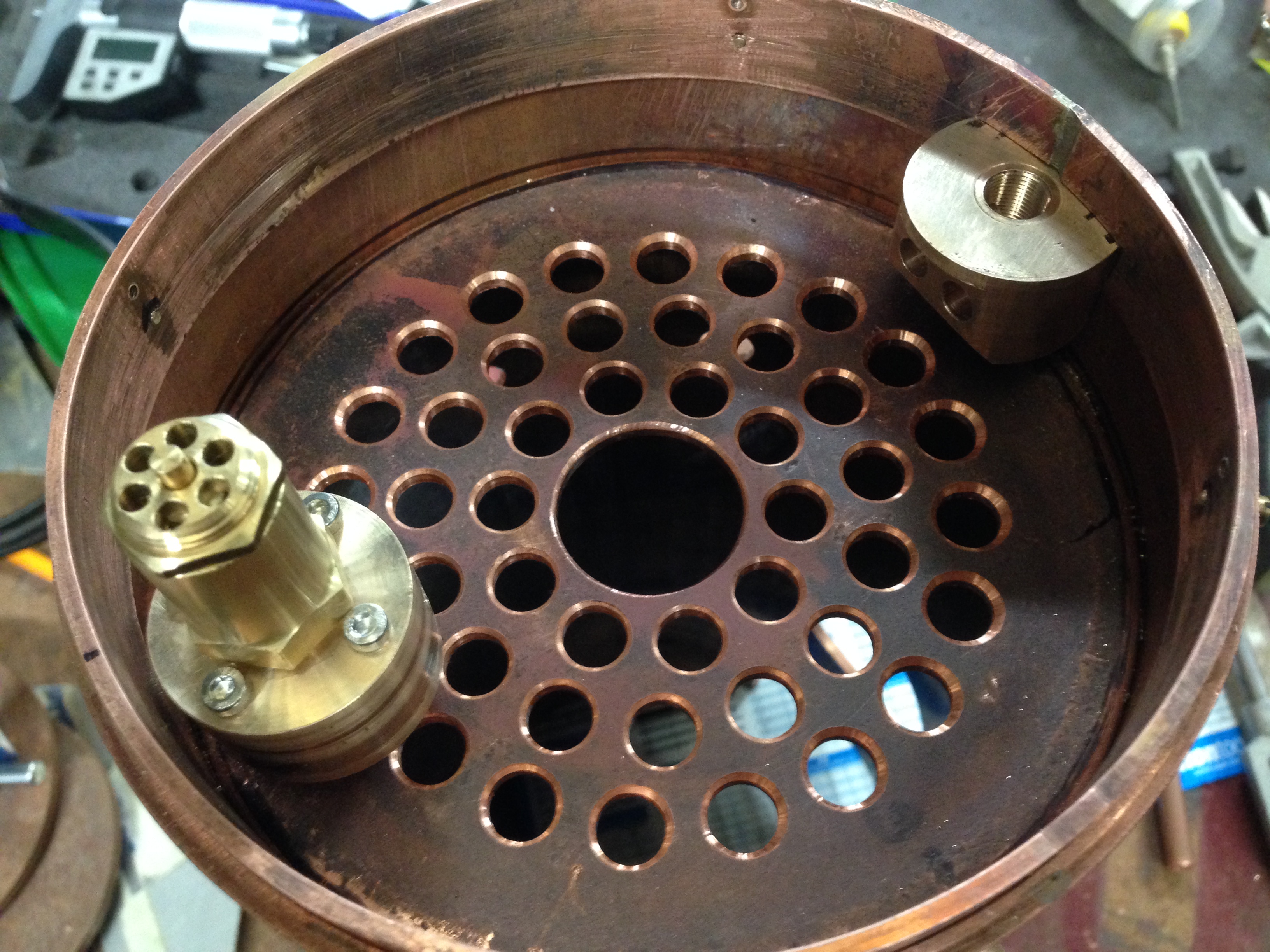
And the 1:8 scale model Trevithick dredger engine. The cylinder is inside the boiler!
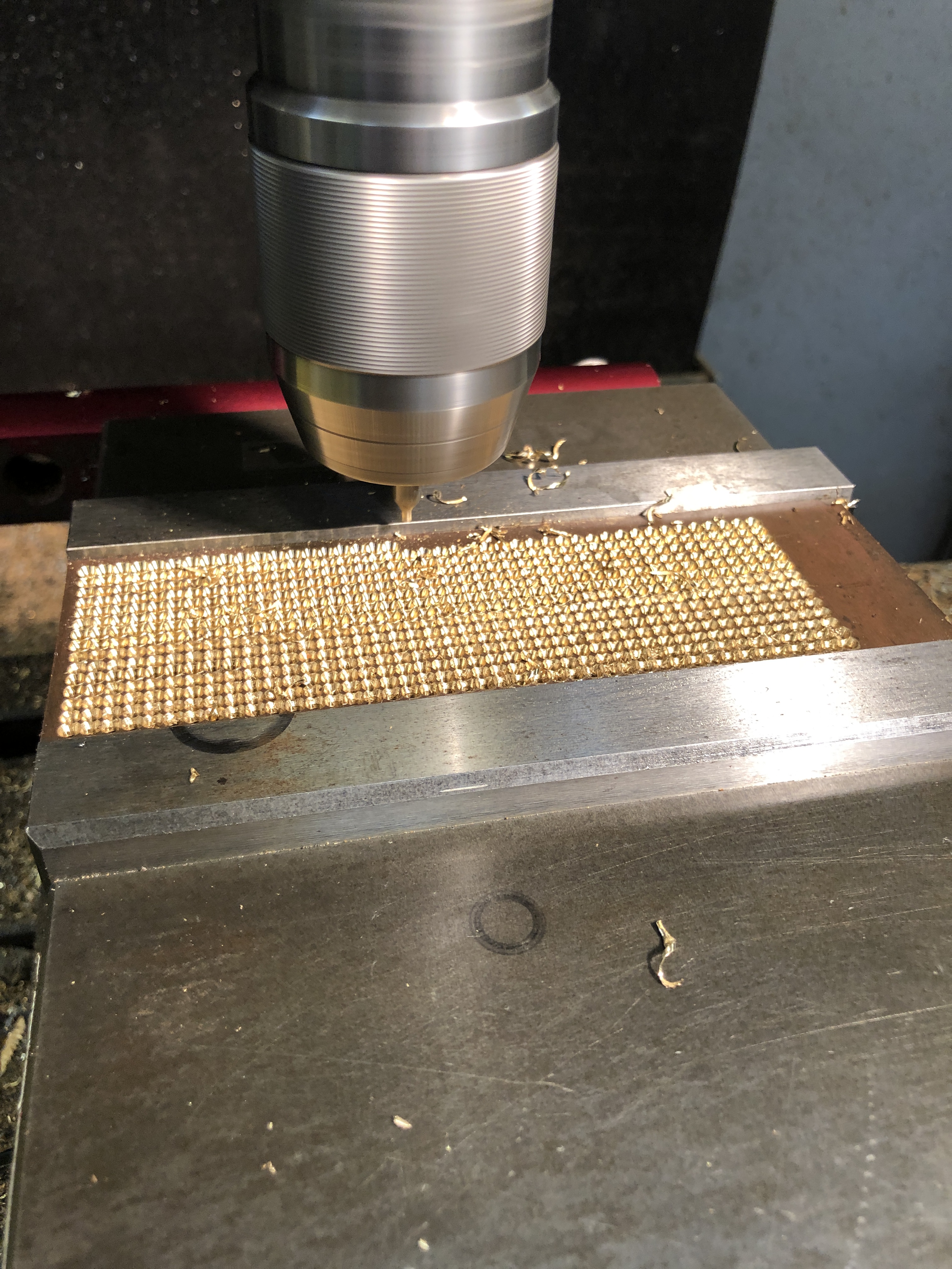
P.S. In case you were wondering, the round column mill modification is still underway. Currently waiting for the column brackets to be cut by the laser cutter.