Book Review… “Making a MARINE TRIPLE EXPANSION STEAM ENGINE OB BOLTON No9 “
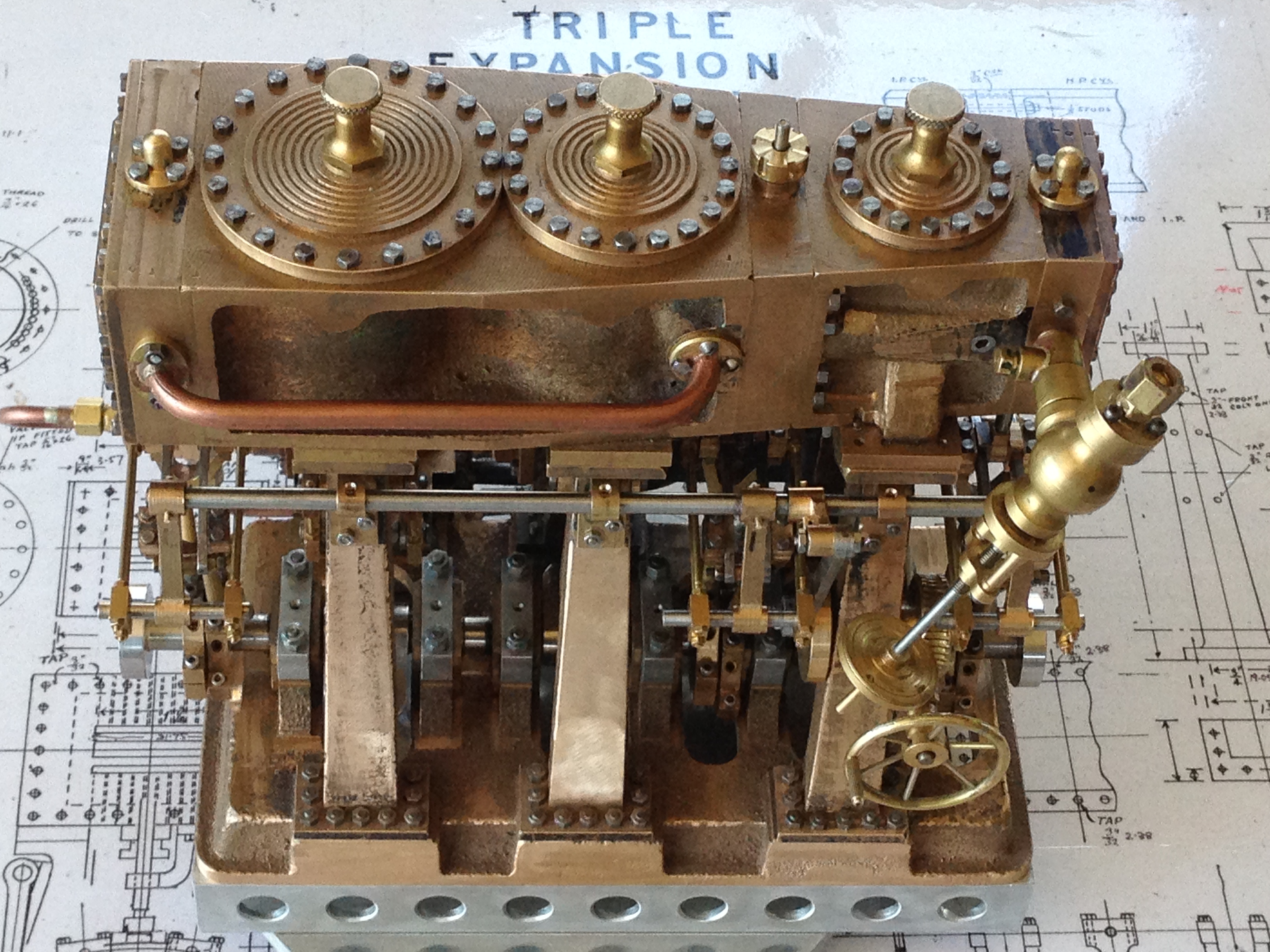
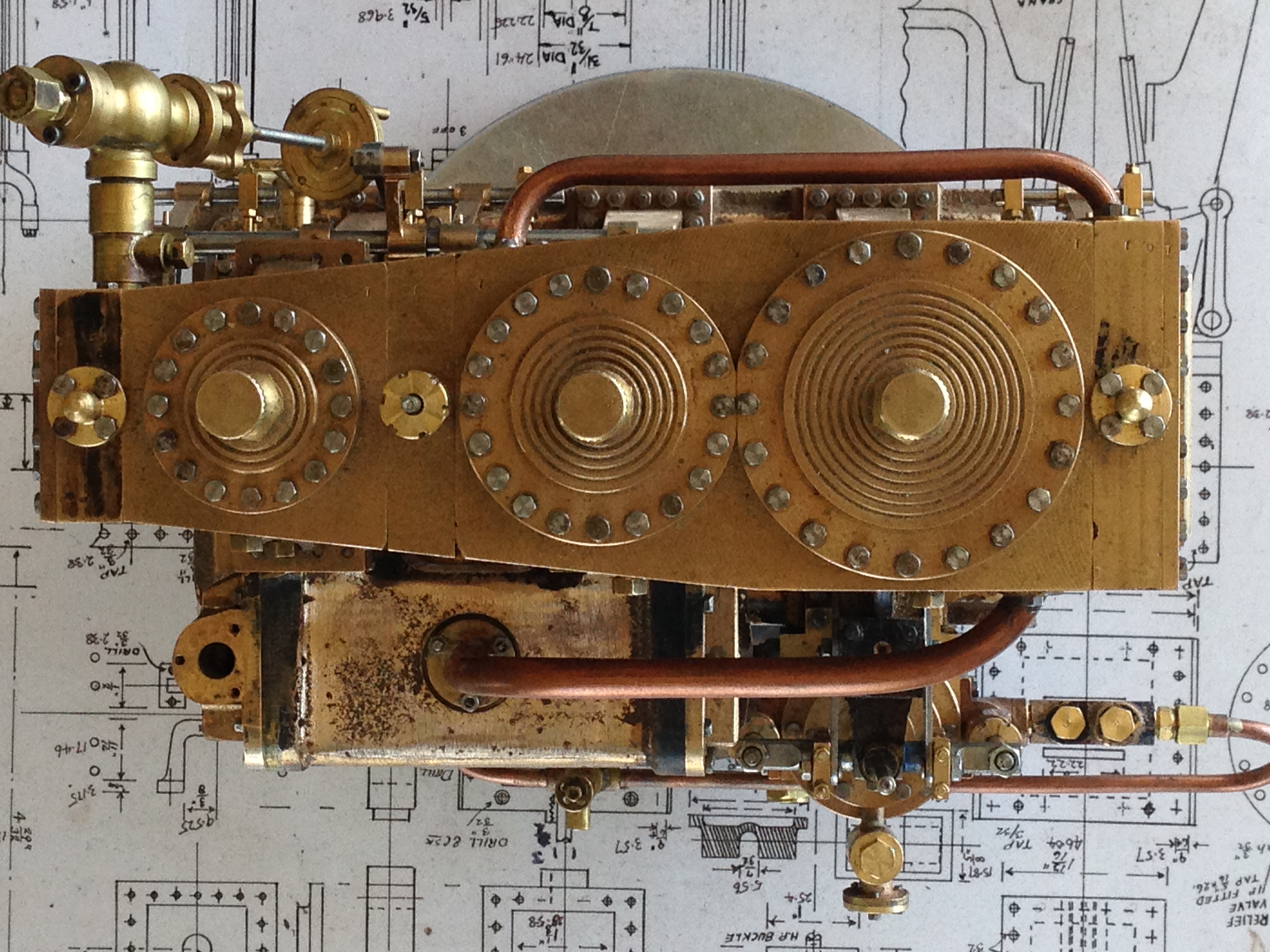
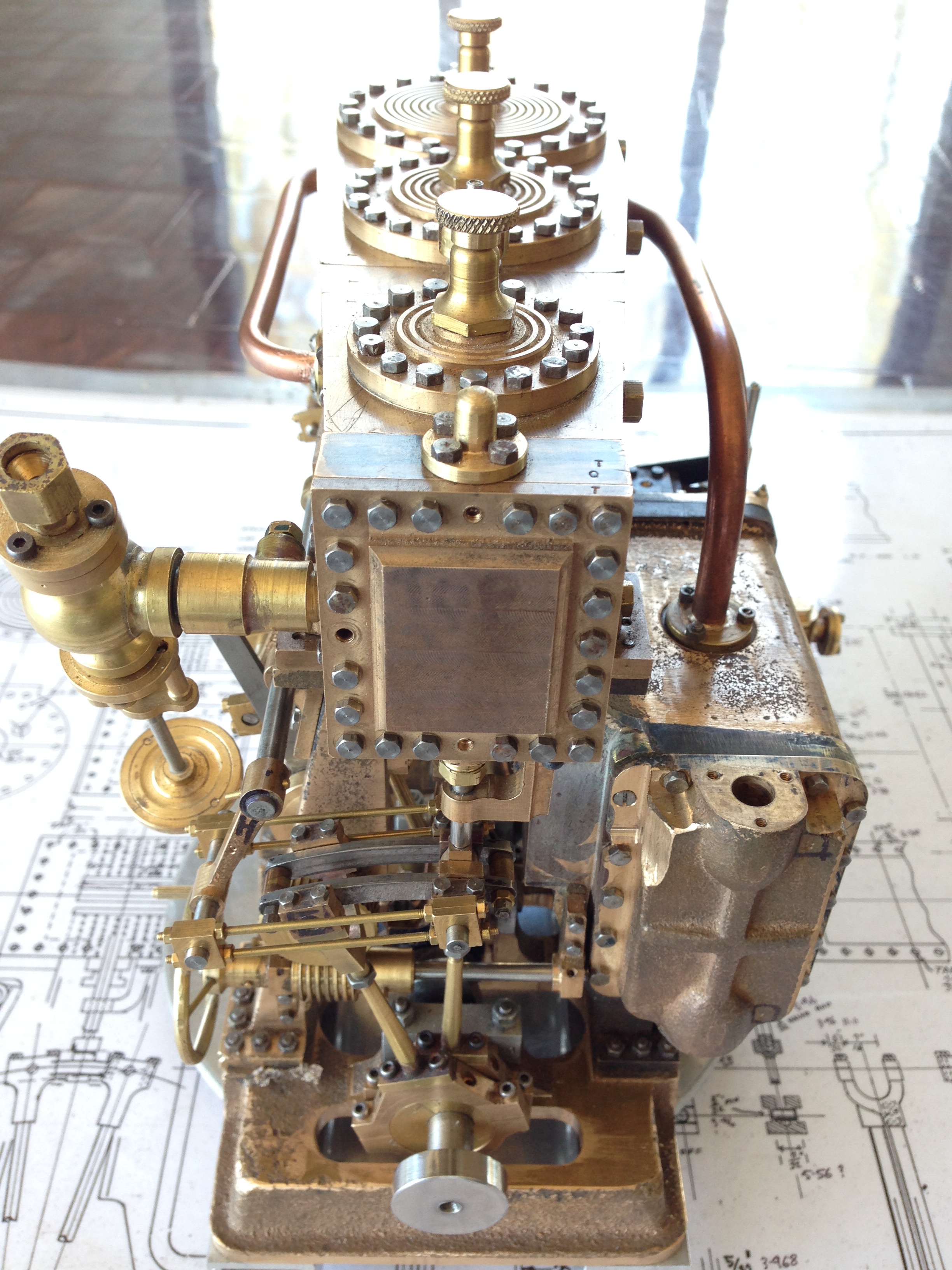
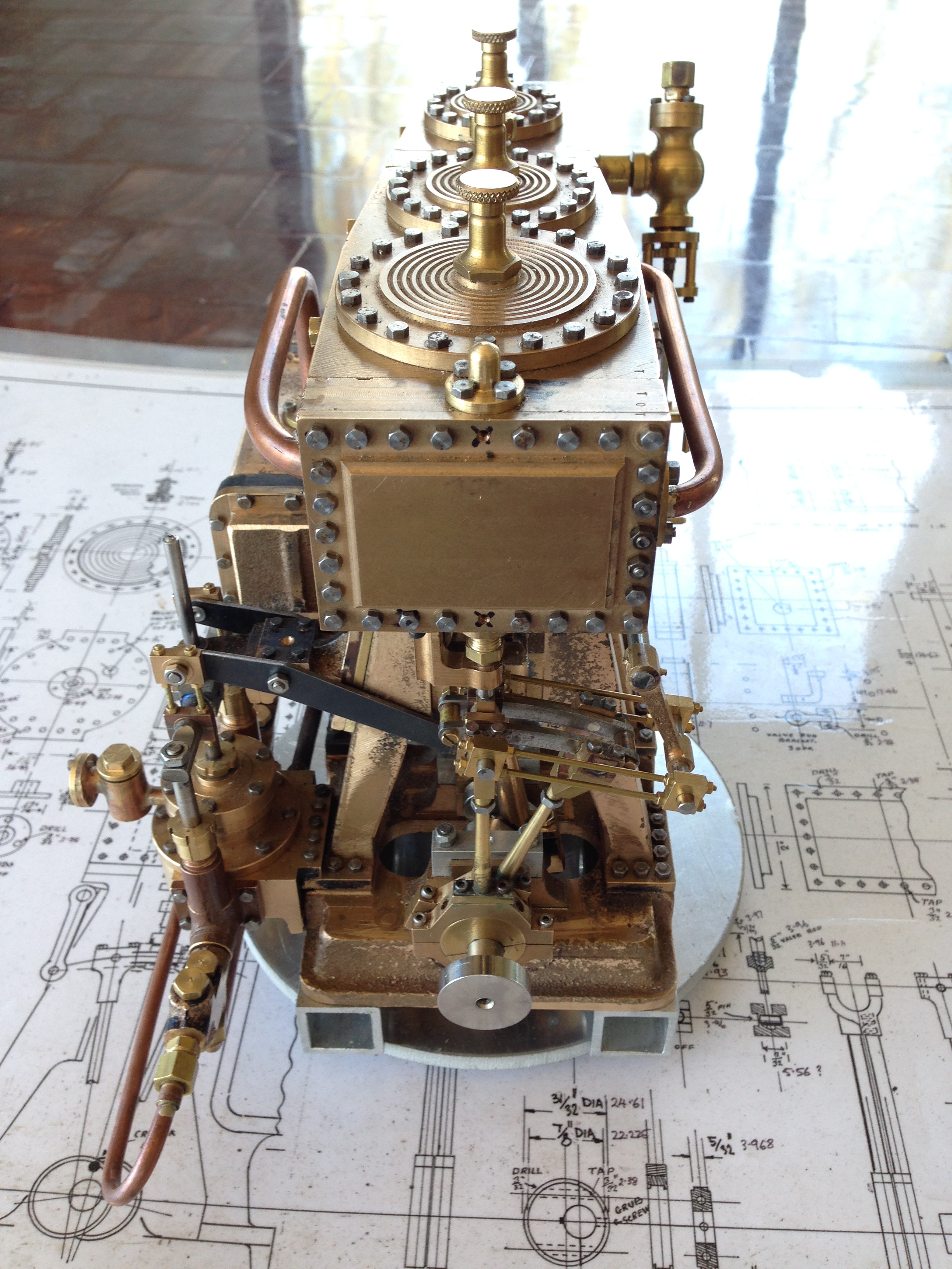
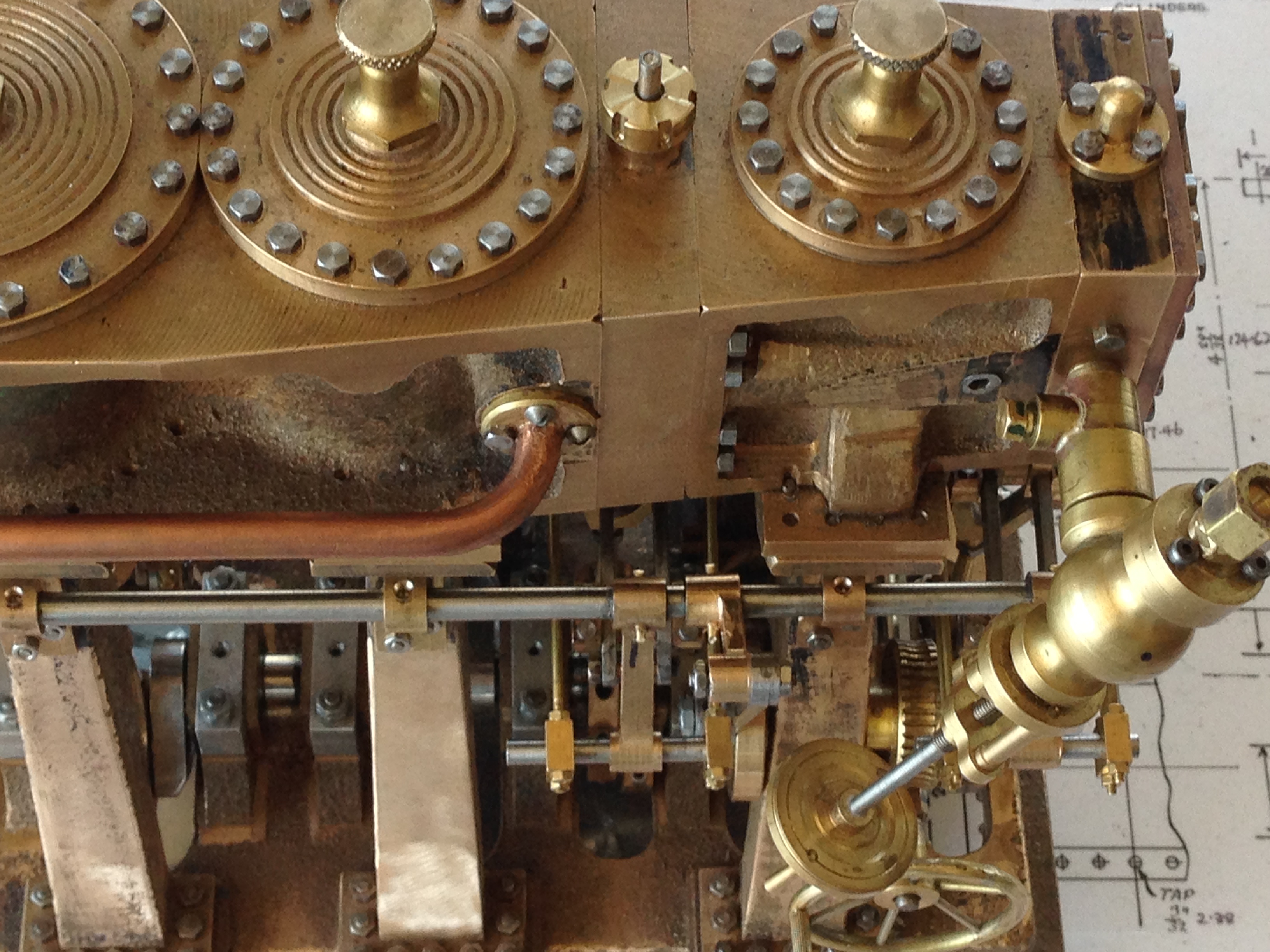
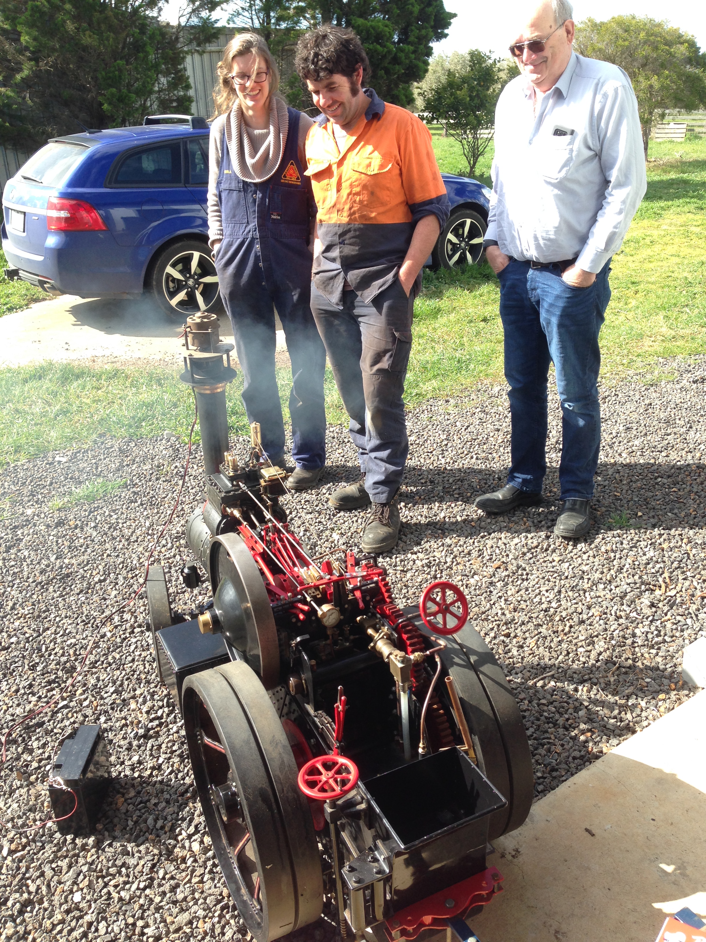
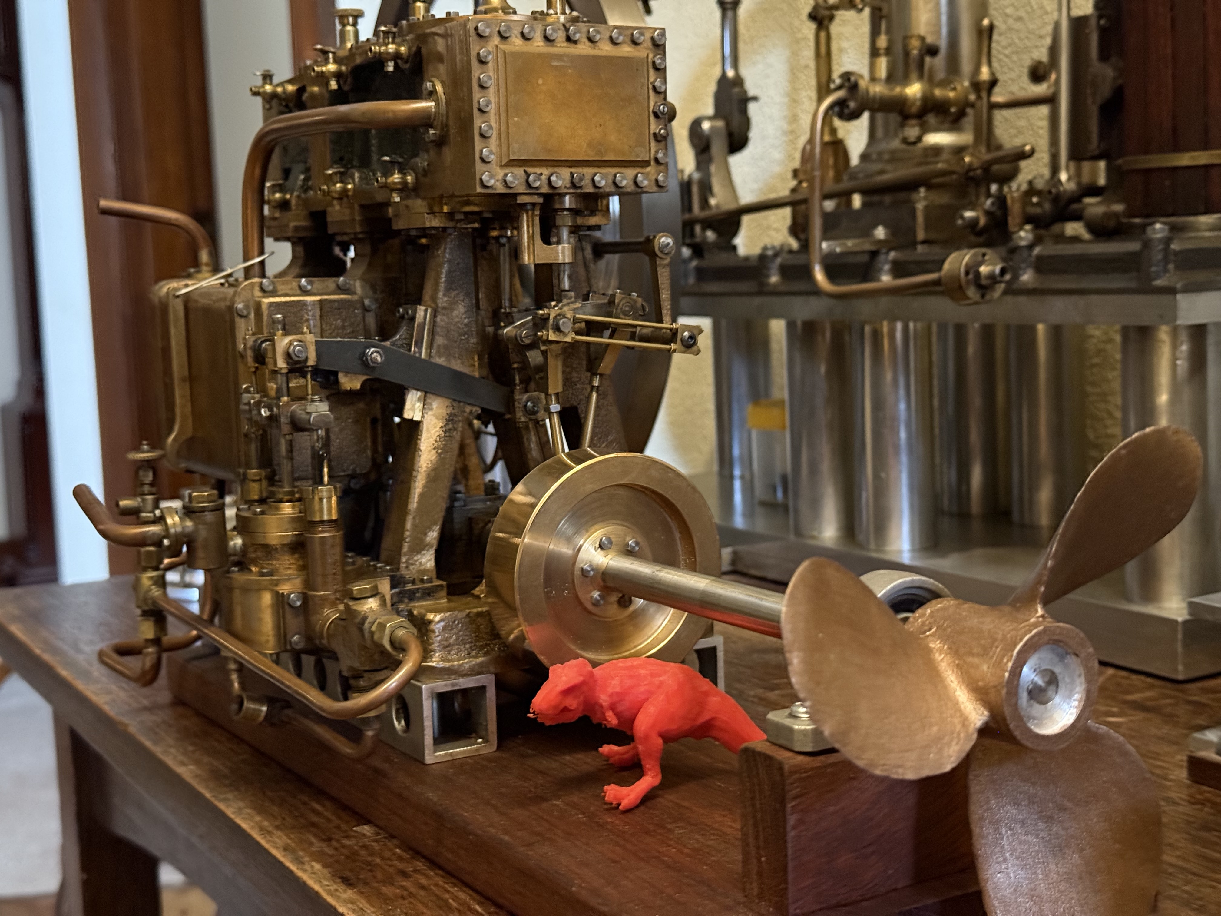
I made a Bolton 9 triple expansion steam engine 2014 – 2017. It took 3 years from opening the parcel of gunmetal and cast iron castings, to running it on compressed air and later on steam. It still runs on steam once or twice each year at our model engineering club’s exhibitions.
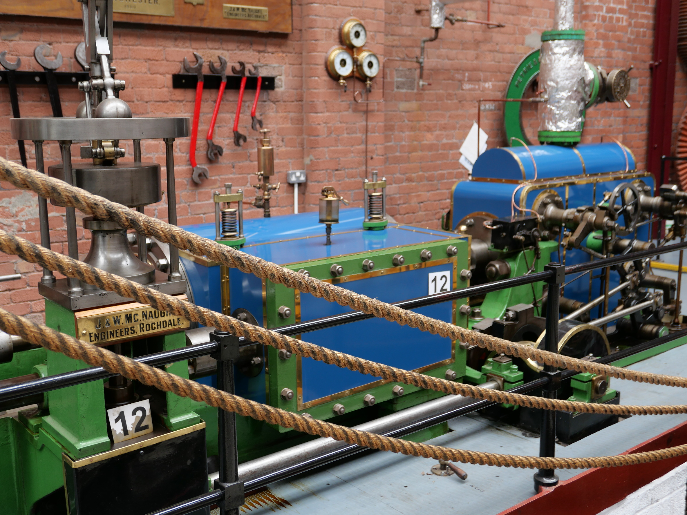
The triple was the third steam engine I made. The first was a Bolton 7 single cylinder mill engine, then a Bolton 12 beam engine, and after seeing them run I felt that I was ready for the more difficult build.
Someone estimated that making a triple expansion steam engine takes 3000 hours. I did not count the hours for mine, but I know that many days in those 3 years I spent between 4 and 12 hours each day. It was the first model which I made after retiring from my occupation. Over those years (and subsequently) I was getting to grips with CNC machining on a lathe and mill, so the time was not exclusively on the triple.
A lot of the triple build is documented on johnsmachines.com, including difficulties, mistakes, and unresolved issues. I used the OB Bolton plans, and the Bertinat articles from Model engineer. And advice from from experienced model steam engineers in my club.
I have looked through the new book listed in the blog title, and read some sections in detail.
Oh HOW I WISH THAT I HAD THIS AVAILABLE 2014-2017!!!

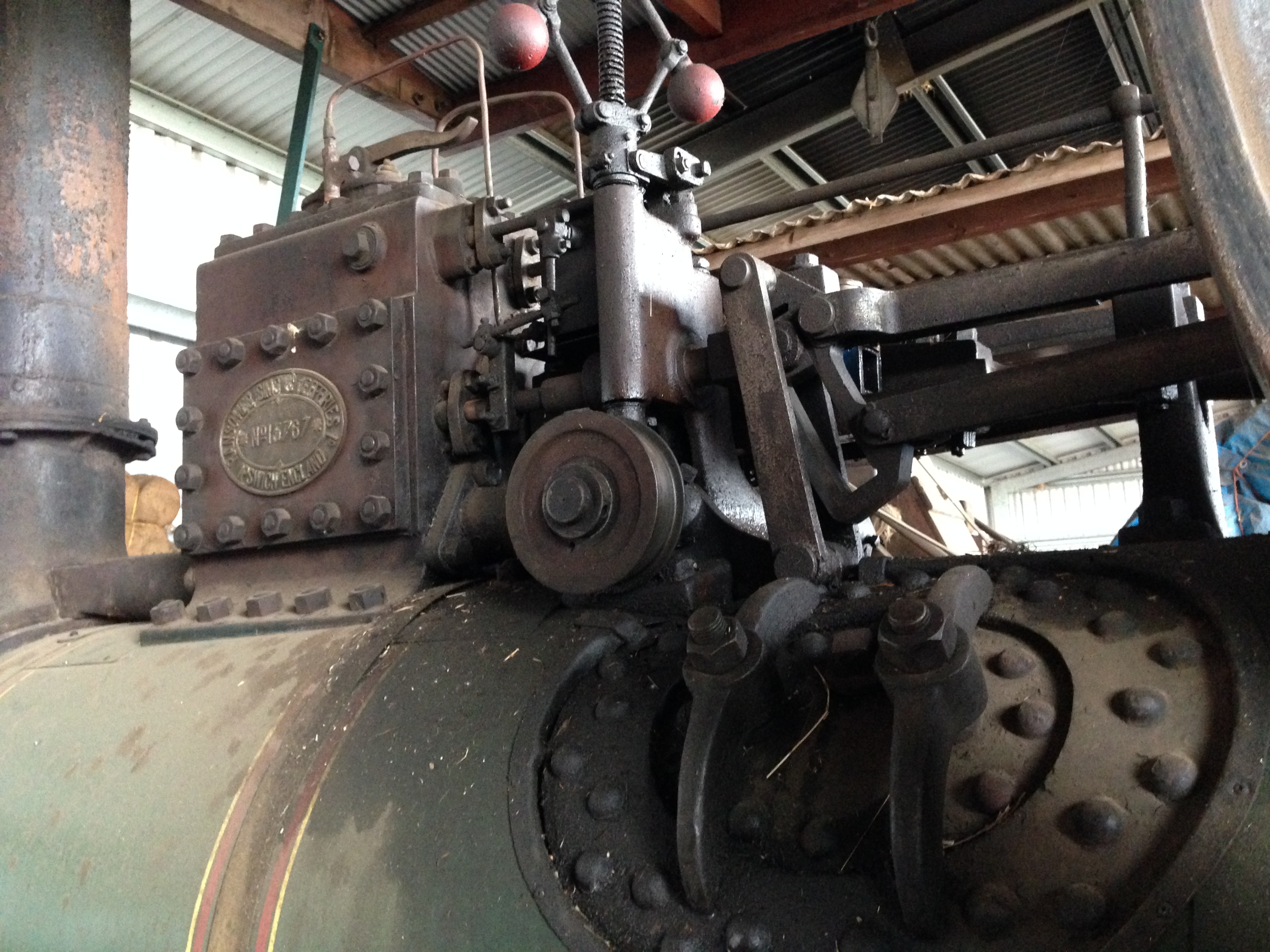
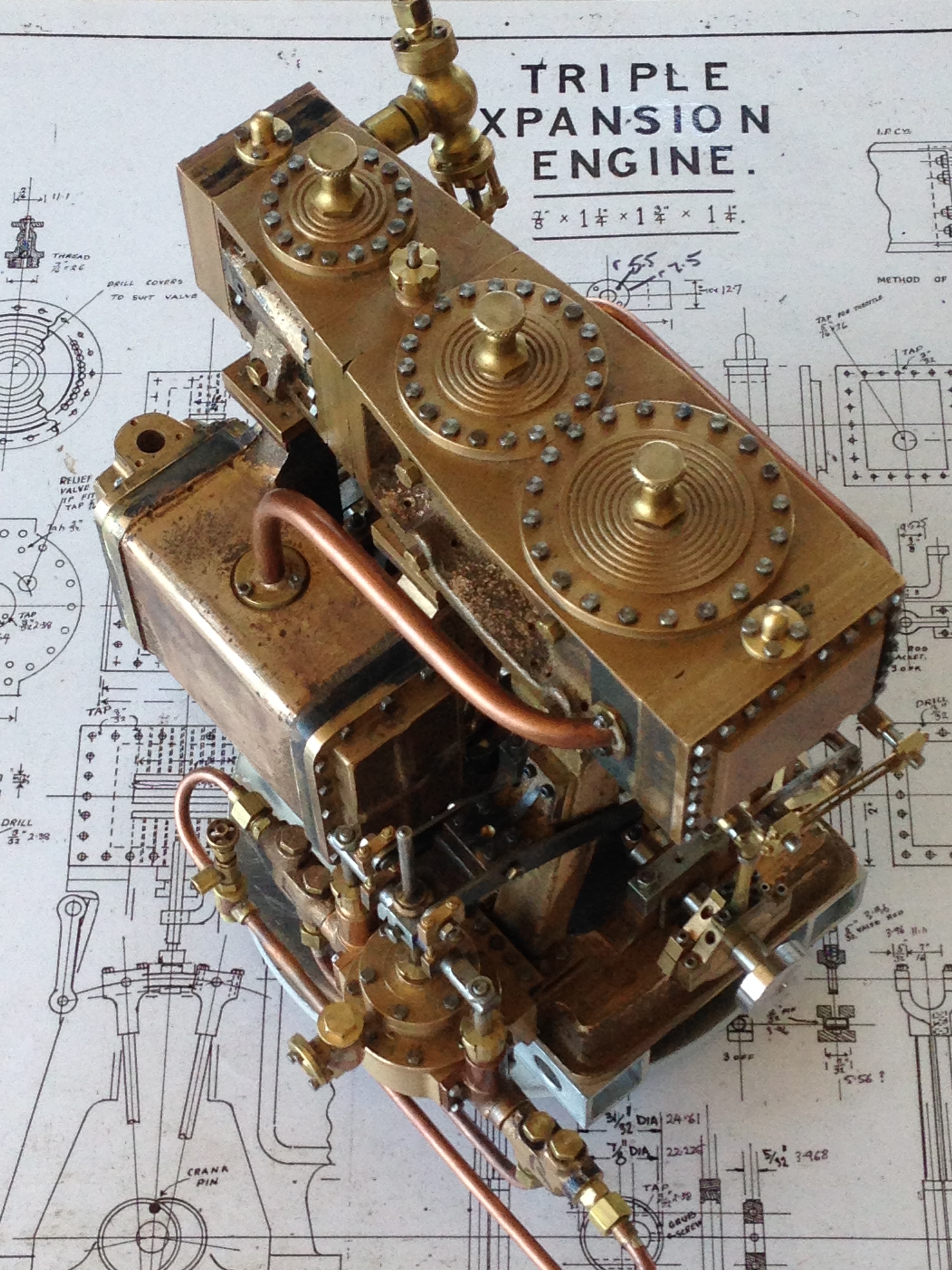
The 2nd edition of the book was published in 2025. It is available from Ben deGabriel at EJ Winter. Costs $AUD39.95 + p&p. There is a separately bound 28 A4 pages of updated CAD drawn metric plans by Ron Collins for $44.95. The 86 page book has a soft cover, A4 format, with many excellent colour photographs and line drawings. It includes a brief history of the Sydney Harbor ferry “SS Kuttabul”, the engine of which was the inspiration for the original Bolton 9 design.
Chapter 3 is a sensible, thoughtful, short summary of “Defining the desired outcome”.
Chapter 4 is 6 pages explaining “Valve events and timing”. I had gradually understood how the triple worked as I progressed with my build, or at least I thought that I gradually understood. I did eventually get the engine working. Having now read chapter four I can see that my 2014-17 understanding was limited. As result of his considerations the author modified the design, particularly the valve timing and he gives a lengthy, clear rationale for the changes.
Chapter 5 “Other Design Considerations” is short discussion on suggesting an increase in rotational inertia by adding a propellor, and choosing the direction of rotation of the crankshaft. I confess that my choice in 2014-17 was random, not rational, and I have now added a propellor, which adds interest from onlookers, and smoothness of engine rotation.
Chapter 6 is another short and useful discussion about the levels of accuracy and precision which should be the builders’ aim. And the use of Imperial and metric measures. Even mixing them for best effect.
Chapter 7 “Painting and Finishing Considerations”. Helpful advice about when to paint components (early), use of stainless steel where possible, and more.
Chapter 8 “General Notes for Other Builders” including jigs and fixtures, Build Sequence, and other Important Notes. For an “intermediate” level builder such as myself, these would have been incredibly useful.
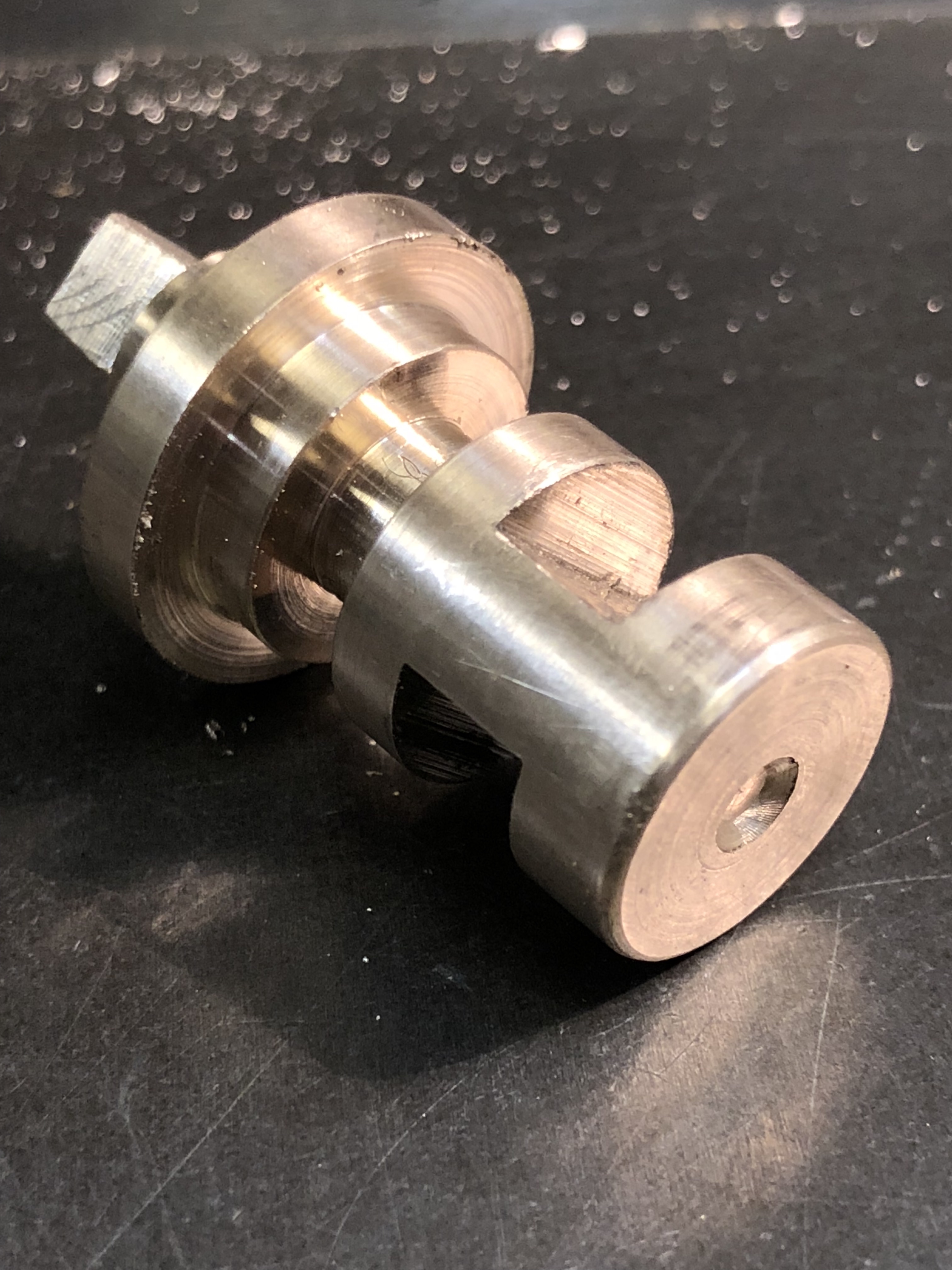
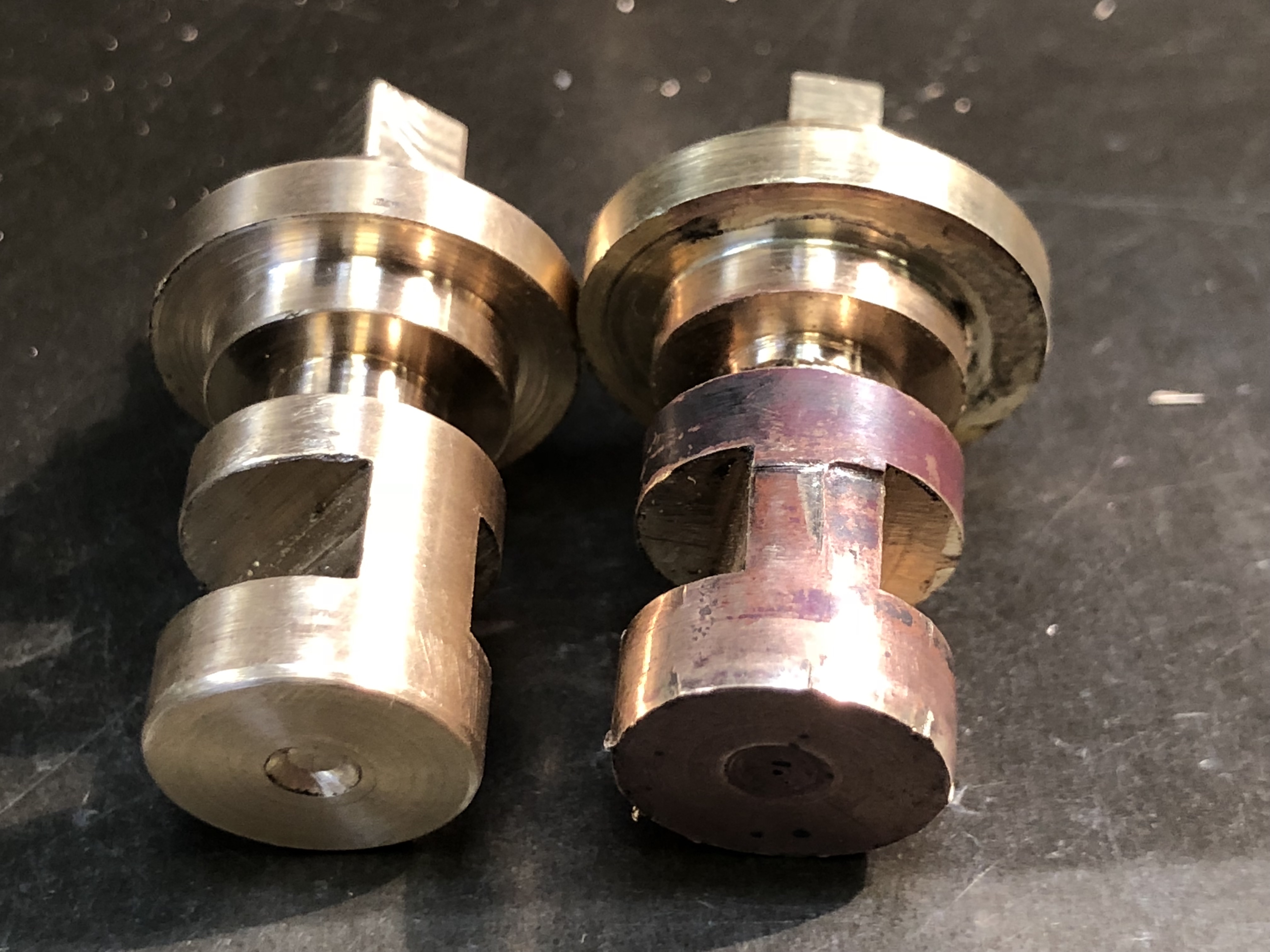
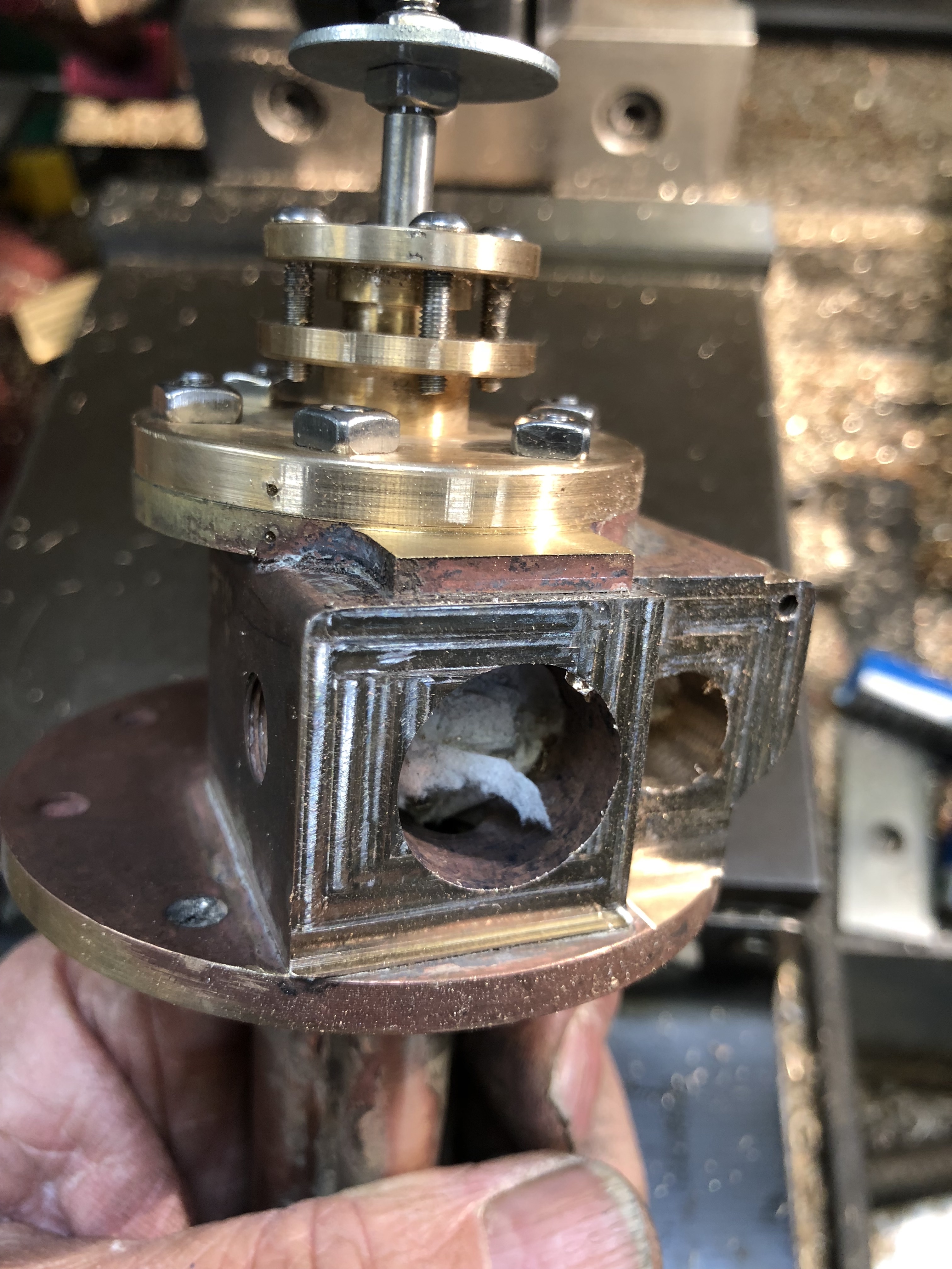
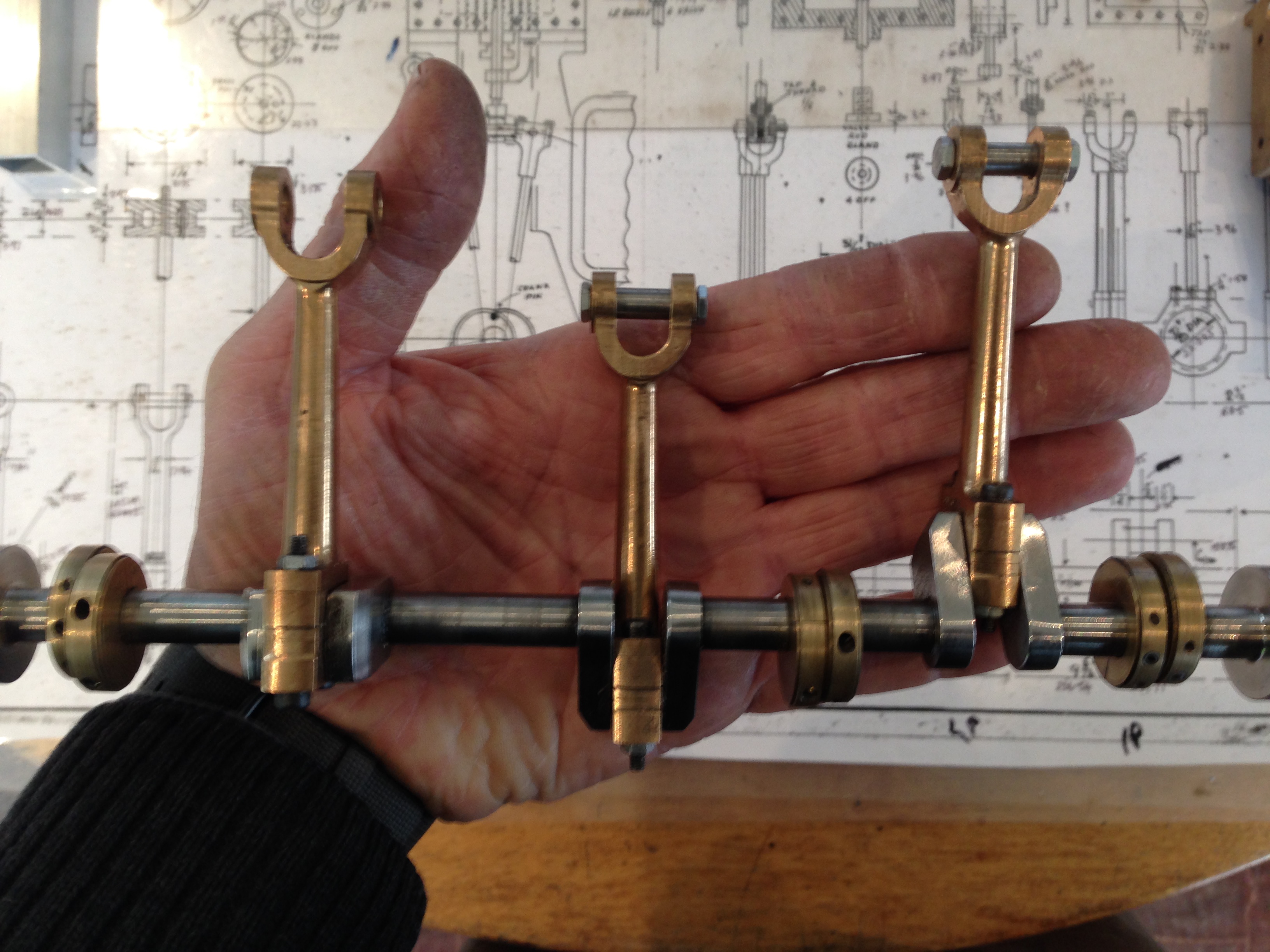
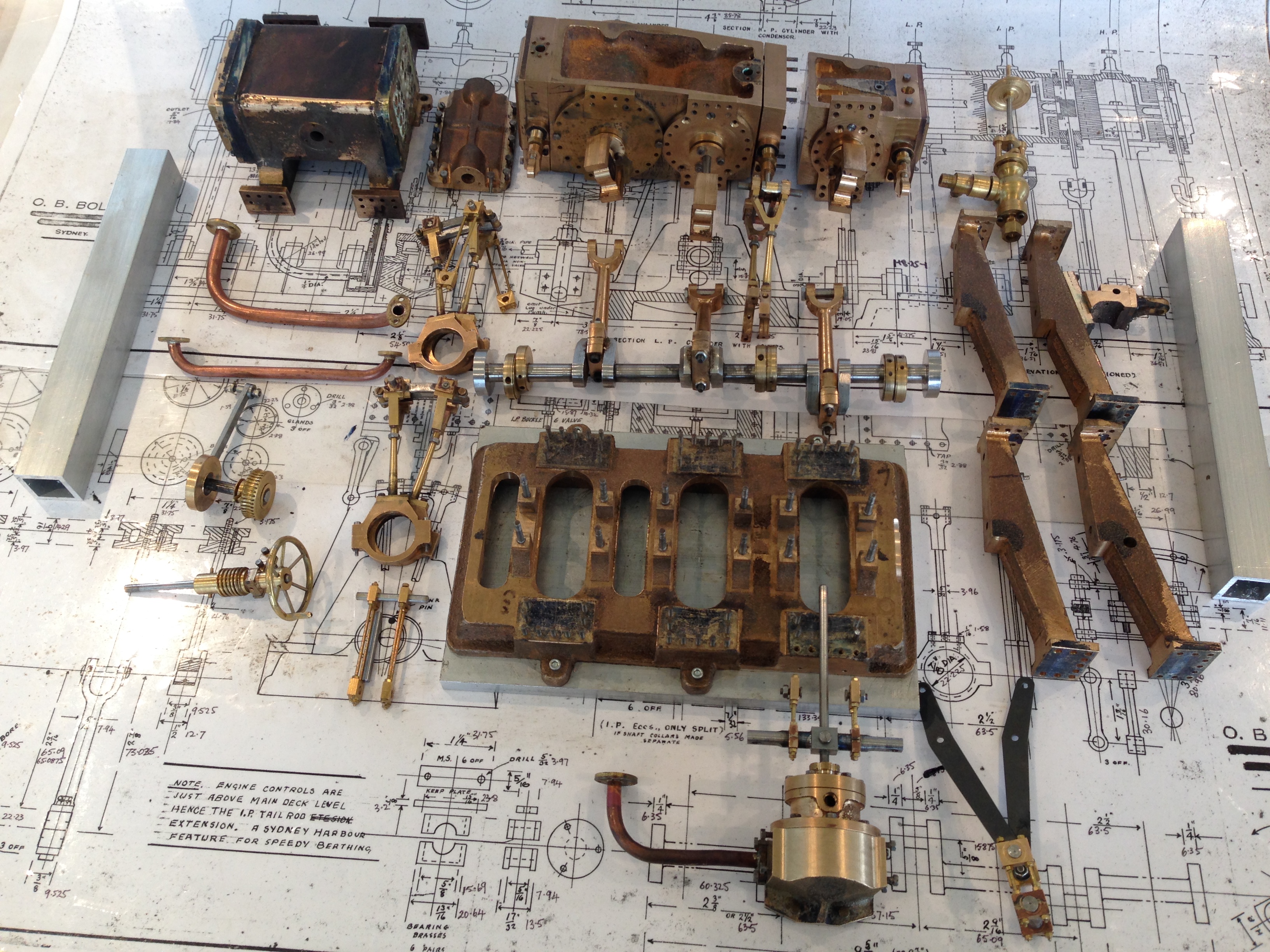
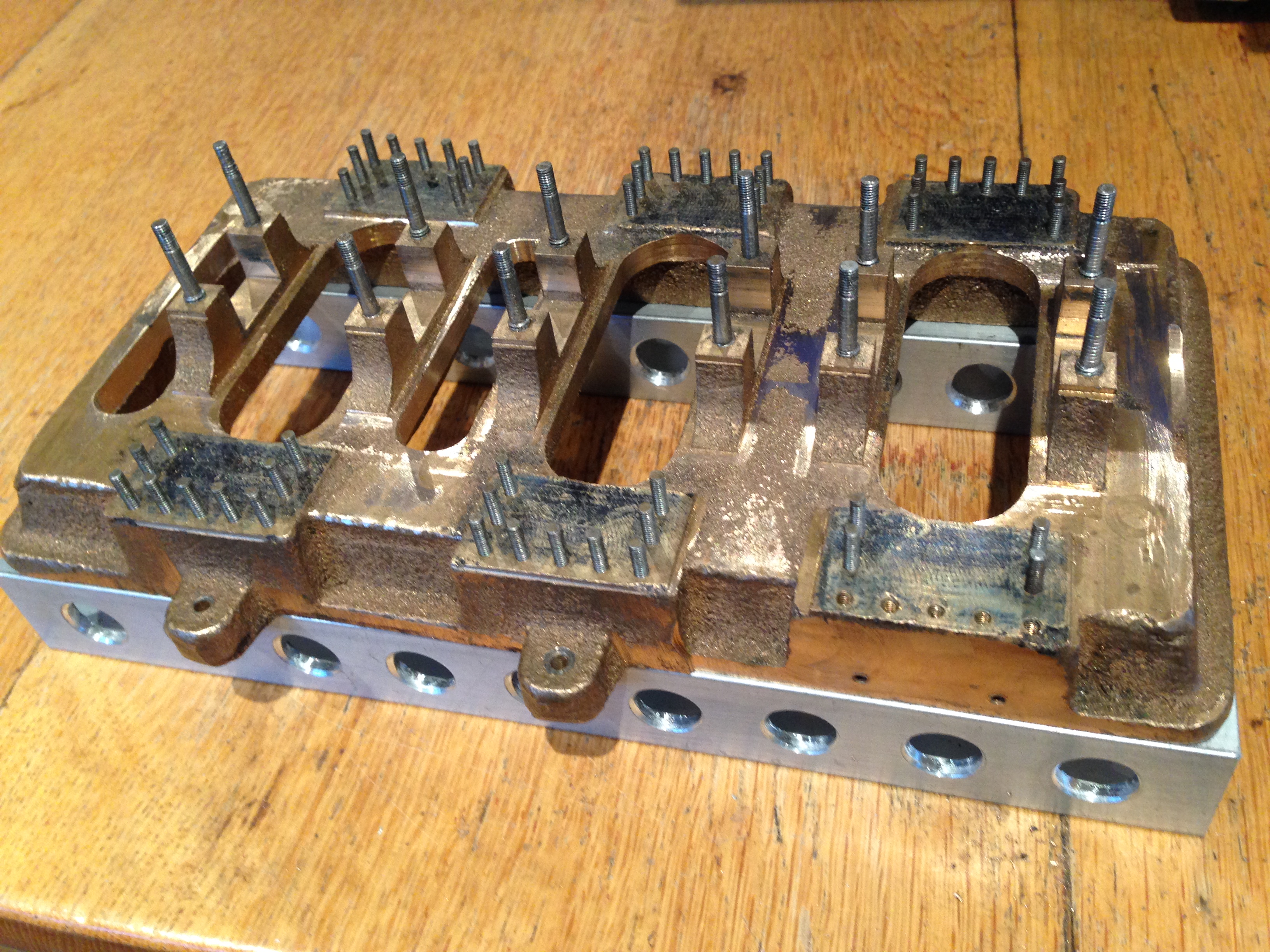
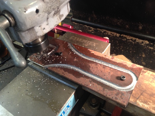
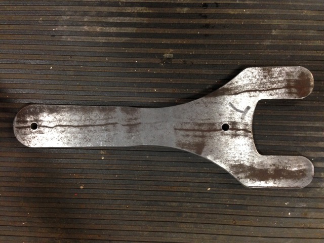
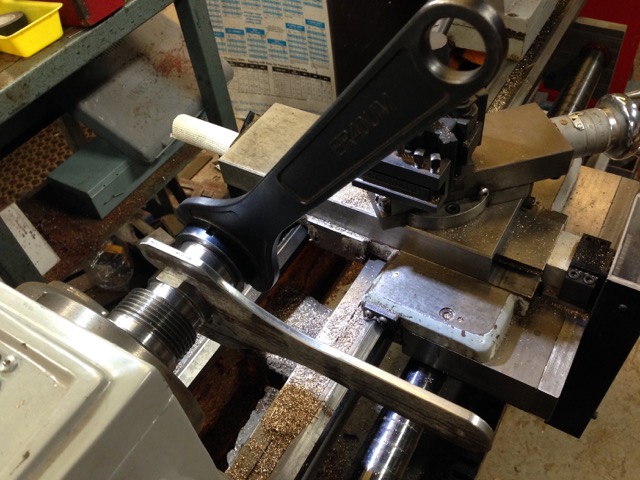
Chapters 9-24 are the bulk of the book, comprising detailed advice on how to make and assemble the various components. Again, how I wish that I had this advice available instead of trying to work out from first principles how to hold and machine the irregular shapes. I did make my crankshaft from one piece of steel instead of the built up method used by Clark, but I have no doubt that his method would be more efficient, and easier than the method I used.
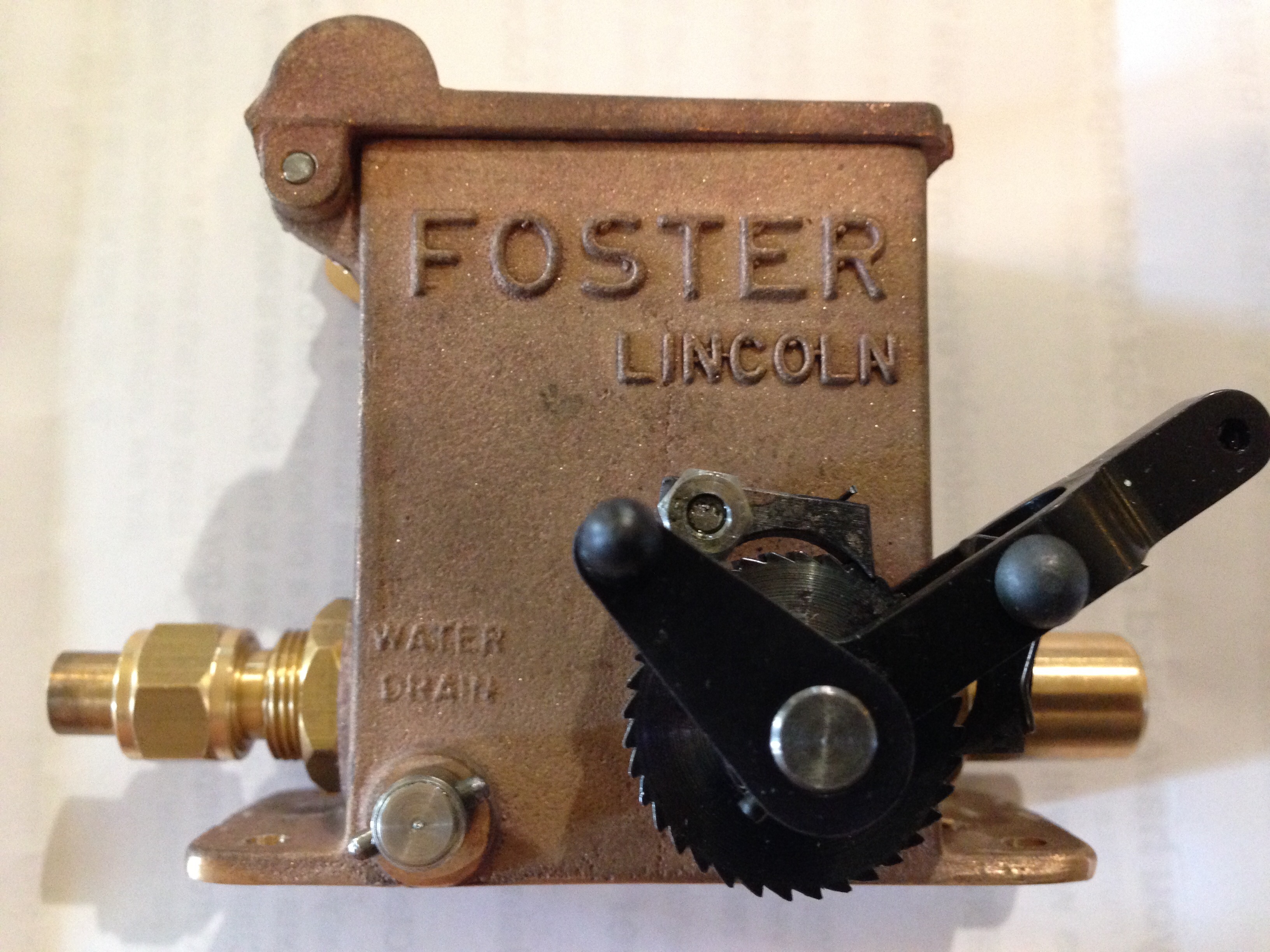
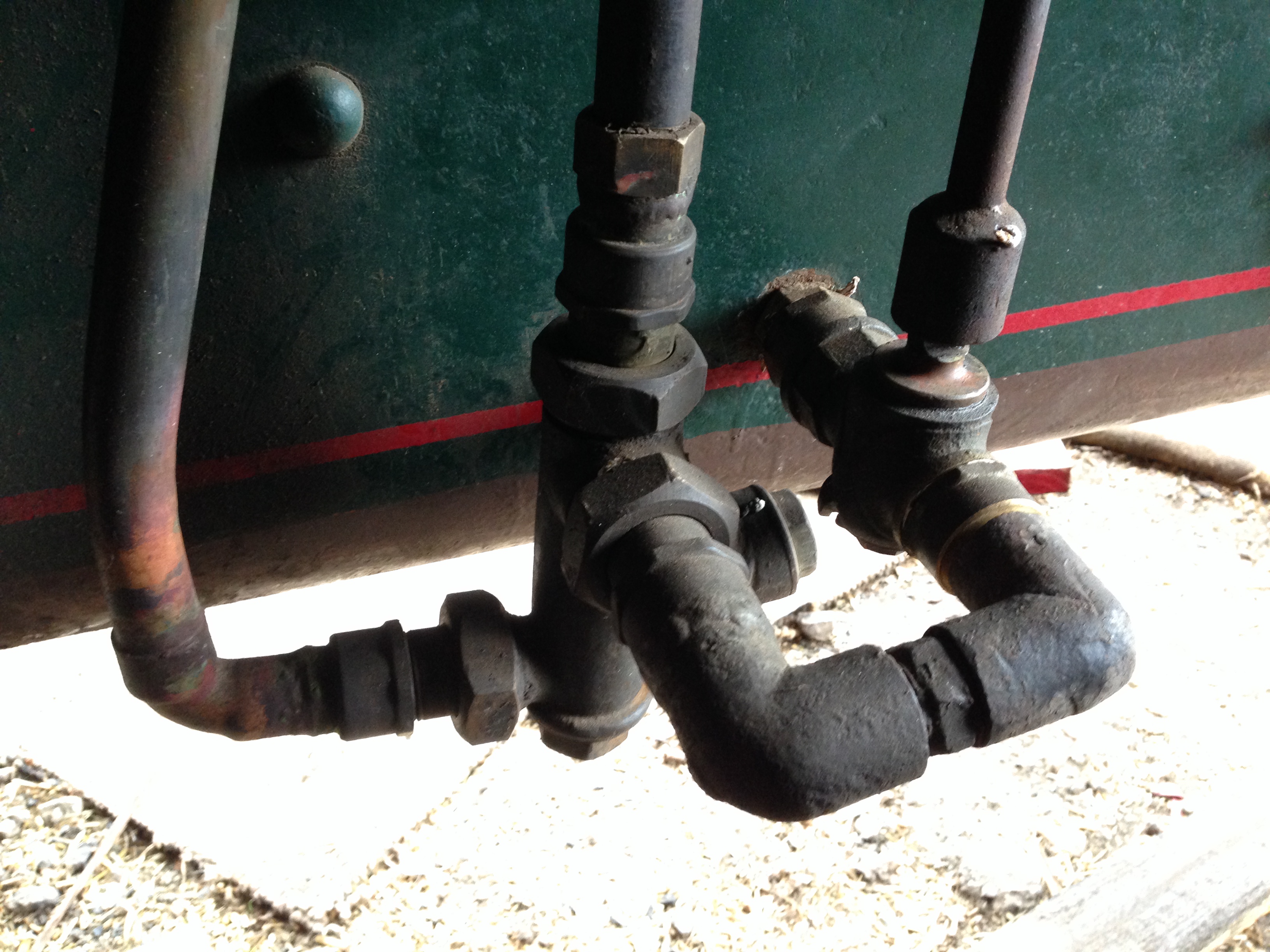
Chapter 24 “Finishing Off. Drains, Gauges and Lubricator.” The OB Bolton and Bertinat plans and text have nothing about these items, so the Clark information is invaluable.
Chapters 25 and 26 “First Test Runs” and “Analysing the Test Results”. Clark suggested different valve settings than specified by Bolton, and gave reasoned justification for his suggested changes. If/when I get around to another tear down of my triple, I will institute his suggestions, and if I am ever crazy enough to build another one, I will build them in.
Chapter 27 “A Display Base”
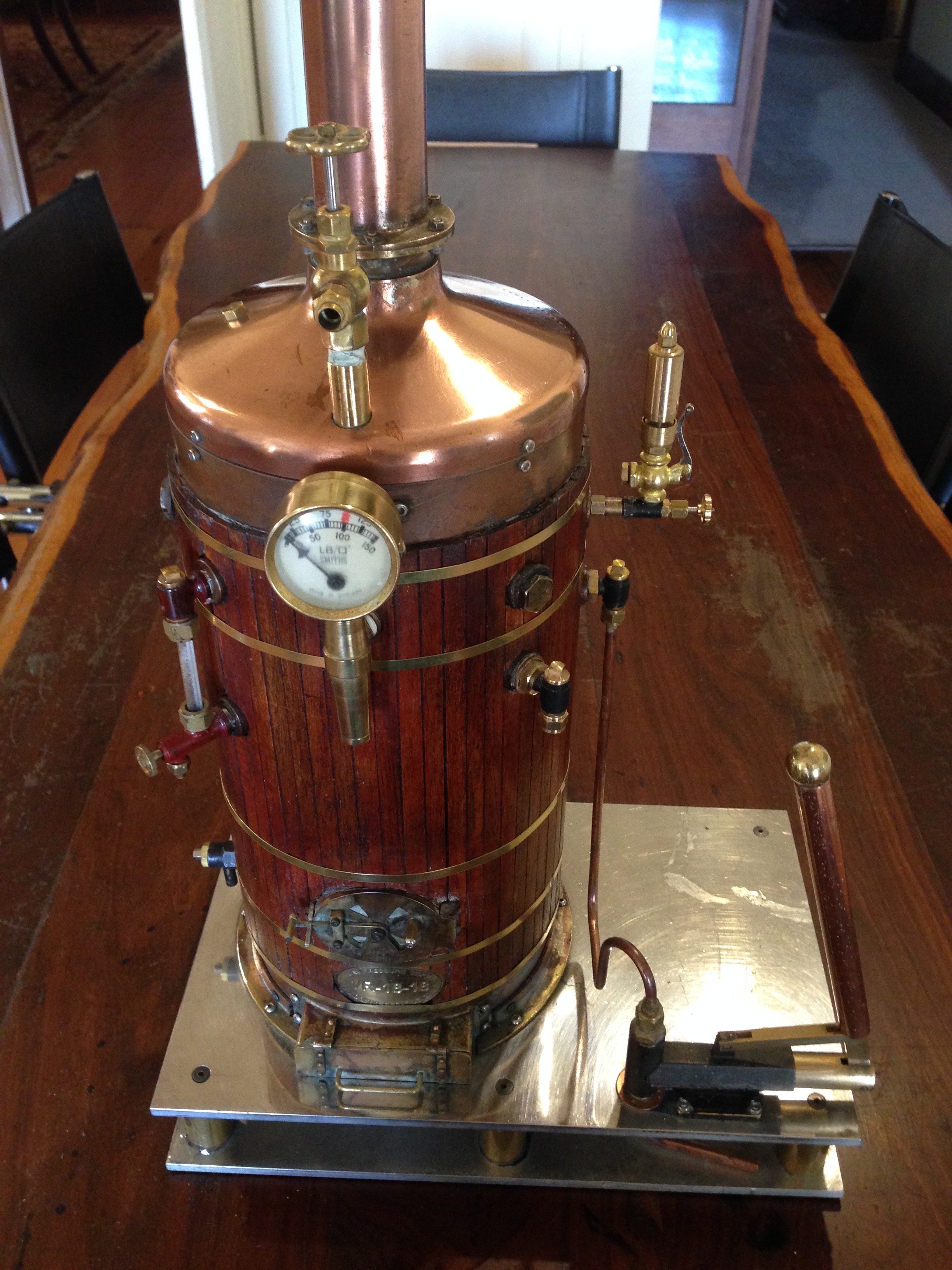
Chapter 28 “Some Display Loads for the Engine”. Including a propellor, a pretend thrust bearing which is actually a large flywheel, and a generating set. Very good and interesting suggestions. Also some thoughts about a suitable boiler. I might add that at exhibitions I run my triple on supplied steam at only 25psi, and somewhat to my surprise, it runs fairly smoothly. I suspect that it is working principally on the high pressure cylinder, with a small contribution from the intermediate cylinder, and only load from the low pressure. When I use my own 6″ boiler I run it at 80-100psi. To operate the engine using all 3 cylinders the condenser should be working, and using cold water.
Chapter 29 “Thoughts for Future Developments” and Finally “Conclusions” “Bibliography” and a very nice “Acknowledgments” page.
The accompanying booklet “Detailed Construction Drawing Set” is accurate, clear, metric, and more detailed than the original OB Bolton plans. And in workshop useful A4 size in a foldback spiral binder, and blank alternate pages for notes and calculations.
So, my conclusion is that anyone contemplating building the Bolton 9 Triple Expansion Steam Engine should definitely spend the extra on top of the castings expense, and get these books. You can thank me (and James Clark and Ron Collins) later for this strong recommendation.
p.s. Ben deGabriel informed me that one of his customers built the Bolton9 triple IN 9 MONTHS, using the Clark book and Collins plans. And that he intends to make another one!!