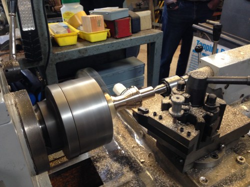
Boxford 125TCL CNC Upgrade
This small CNC lathe was converted from the original c1985 electronics, to components which are compatible with a PC running Windows XP and Mach3.
Reader Paul M asked about circuit diagrams. I must confess that I do not have such. Indeed, I would not understand them. The electronic connections were made by my expert friend Stuart T. I believe that Stuart intends to write up the conversion for one of the Australian magazines, and possibly this post might give him a gentle shove~.
In passing, I should give Stuart a thumbs up for his excellent CNC lathe program, which is far superior, in my opinion, than Mach3 for running the CNC lathe. It is called Ezilathe and is available as a free download.
Anyway Paul, here are the promised photographs of the electronic components of the Boxford, after the conversion. You should be able to work out many of the connections by zooming in.
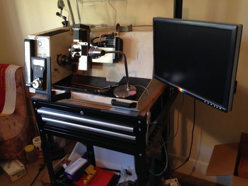
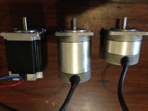
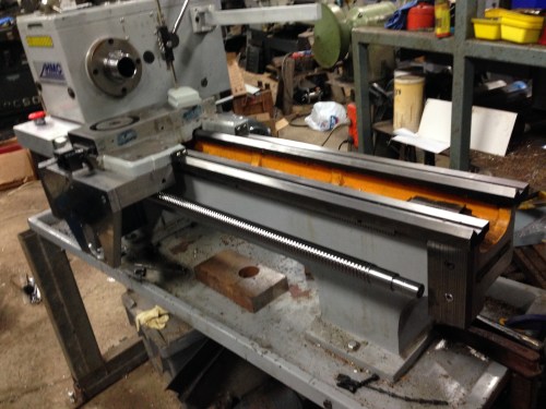
The Boxford 125TCL sitting on a bought trolley which could have been made to measure. The PC is on the bottom shelf, the extra toolholders and tools in the drawers, the wireless MPG on the front, and upgraded stepper motors in black.

The rear view to show the extra power outlets to supply the screen and PC. I still operate this lathe in a spare bedroom of my house. Very handy if I have a sleepless night. It is so quiet that it does not disturb SWMBO.

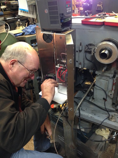
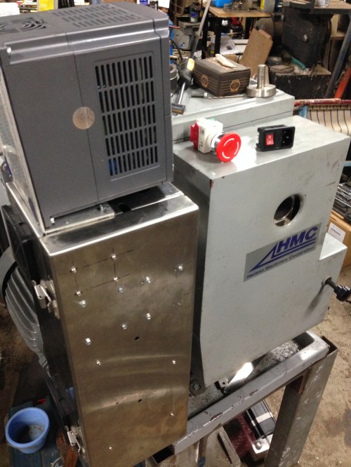
The view with the back open. The only components from the original setup are the spindle motor, the main switch, and the Gemini controller (RHS with orange cover).
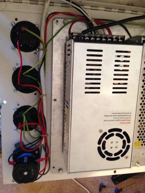
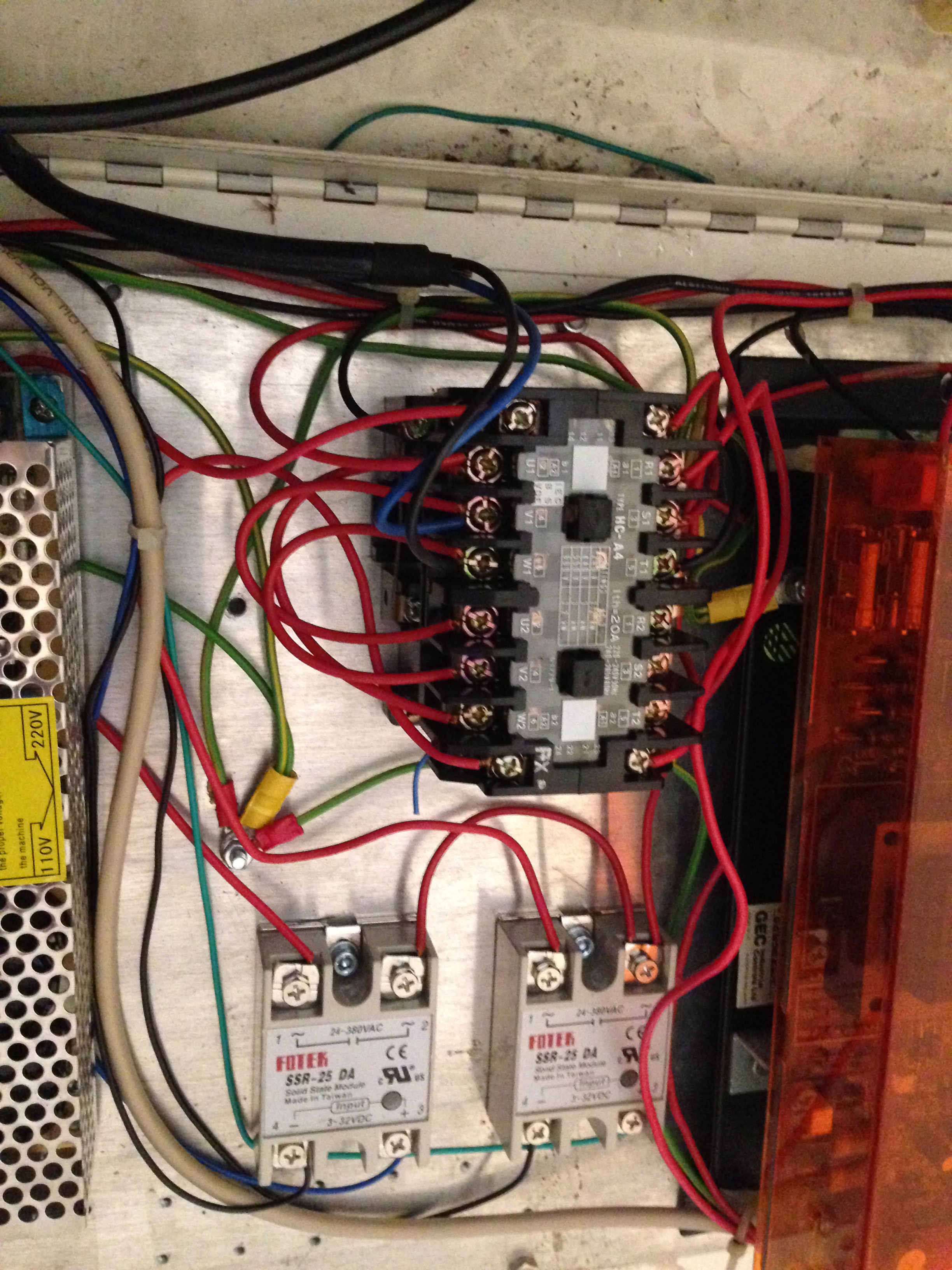
Power outlets, main switch and power supply.
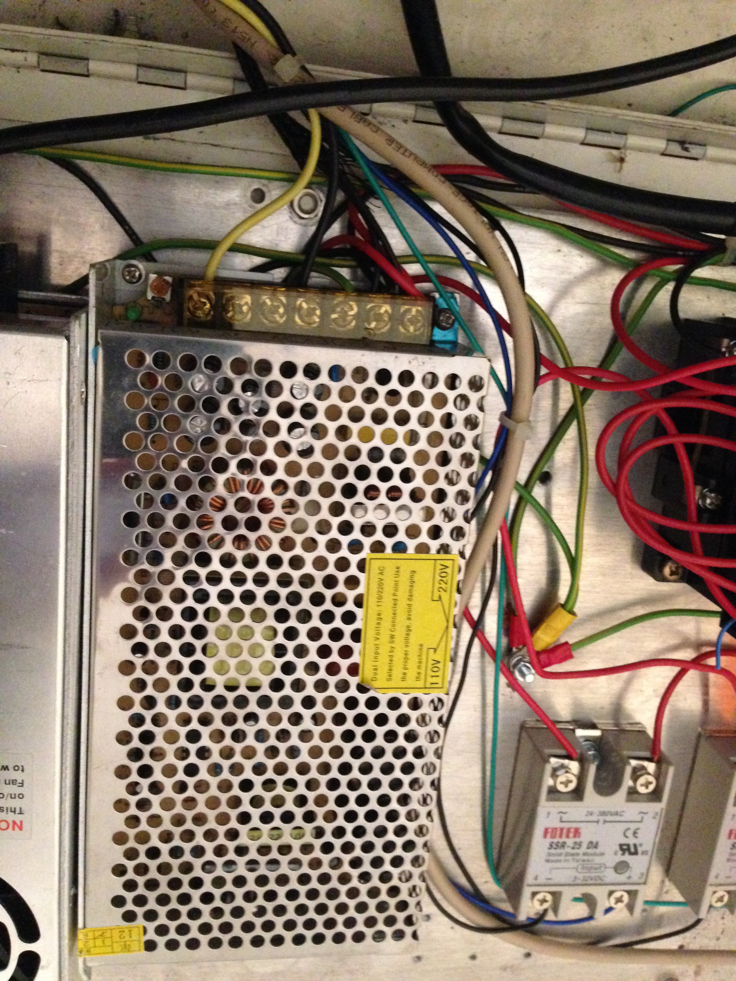
Transformer. Can’t remember what the Fotek is for.

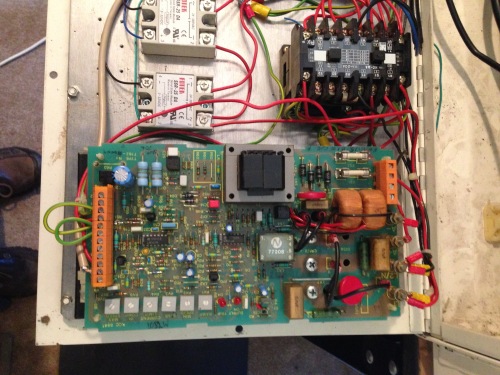
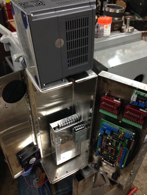
Gemini with cover removed.

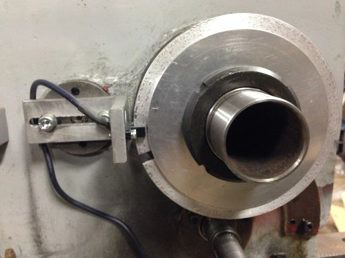
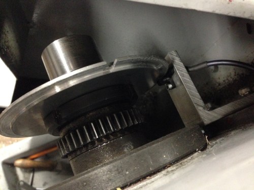
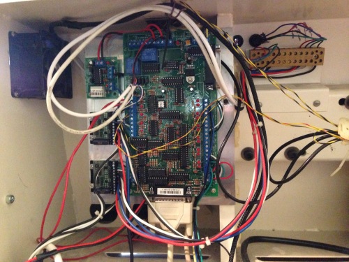
C11 R9 Breakout board, the optical indexer (top), and Gecko stepper drivers (LHS), parallel cable from the PC, all mounted on an aluminium plate.

Spindle motor, original. But now considering upgrading to a more powerful motor.

new cable junction box for the stepper cables.
New cooling fan, top LHS
So, I hope that these shots are some use. If you do not recognise the components, I suggest that you follow my example and bribe an expert friend to do the connections.