
johnsmachines

machines which I have made, am making, or intend to make, and some other stuff. If you find this site interesting, please leave a comment. I read every comment and respond to most. n.b. There is a list of my first 800 posts in my post of 17 June 2021, titled "800 Posts"
Tag: johnsmachines
July 20, 2024
Painting Constitution.
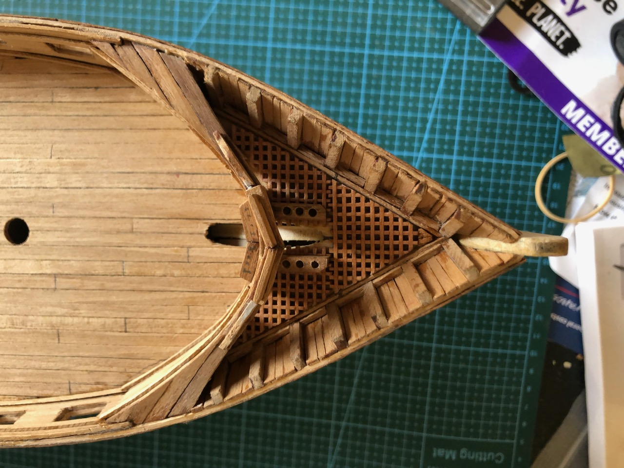
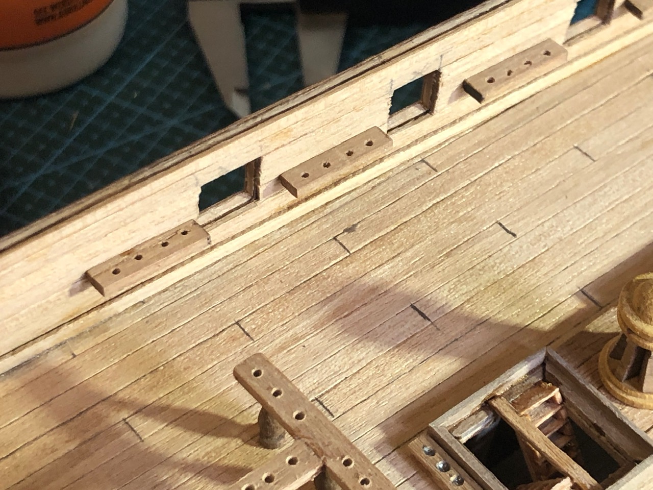
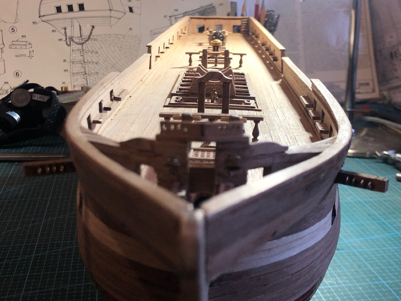
I have reached the point in constructing USS Constitution that the hull needs to be painted or varnished, particularly the exposed deck. When the masts and rigging are installed any painting of deck features will be almost impossible.
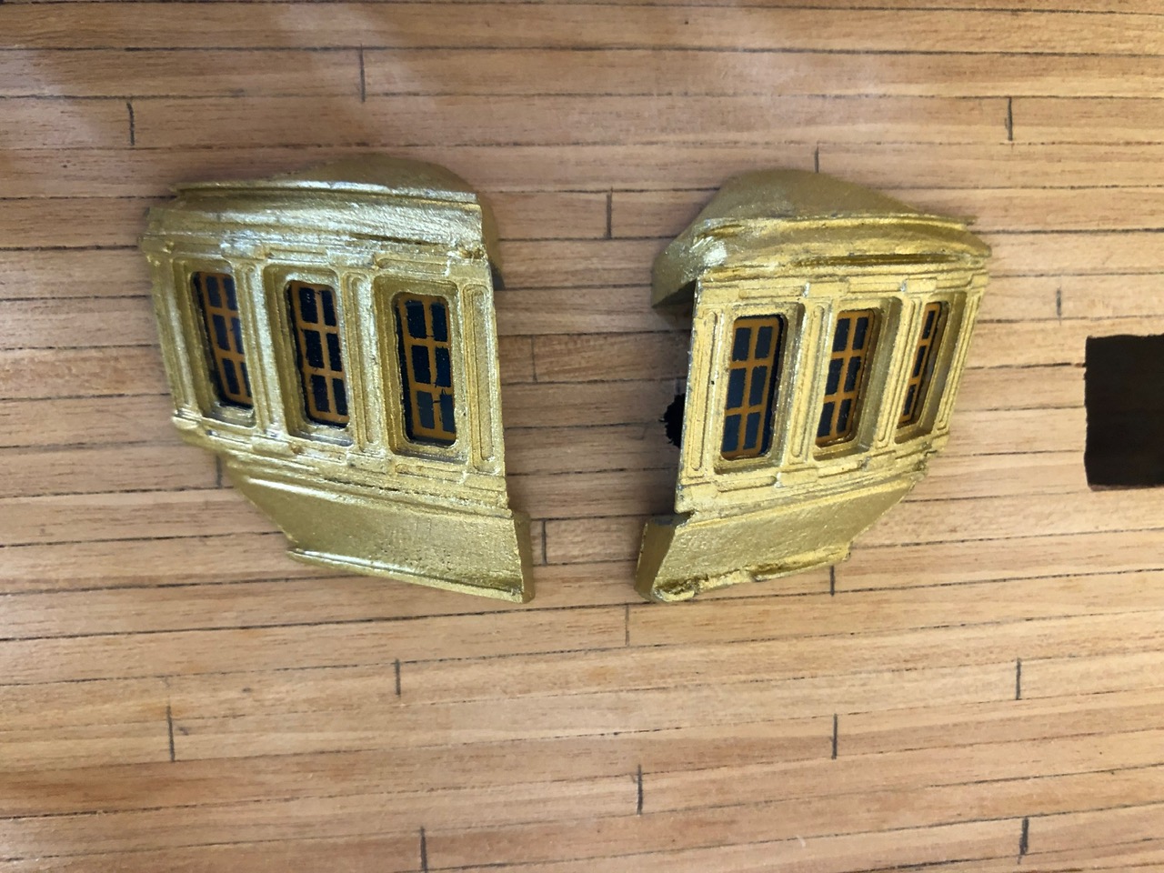
The original ship was mainly painted black, with white highlights, and some red-brown items. I have decided, with encouragement from SWMBO, to mainly use the natural wood colours for the hull and deck, but maybe using red-brown for the gun carriages, and white and gold and black for some small features.
The Mamoli model is not an exact scale model of the original. And I did not aim to make a model to “exact” scale, or to exactly the original colours. In fact, my aim is to make a model reasonably based on the Constitution, which will be an interesting and attractive display in our home.
The hull has had wood grain filler applied, and 2 coats of satin polyurethrane to all surfaces except the copper sheathing. Still contemplating whether to coat the copper.

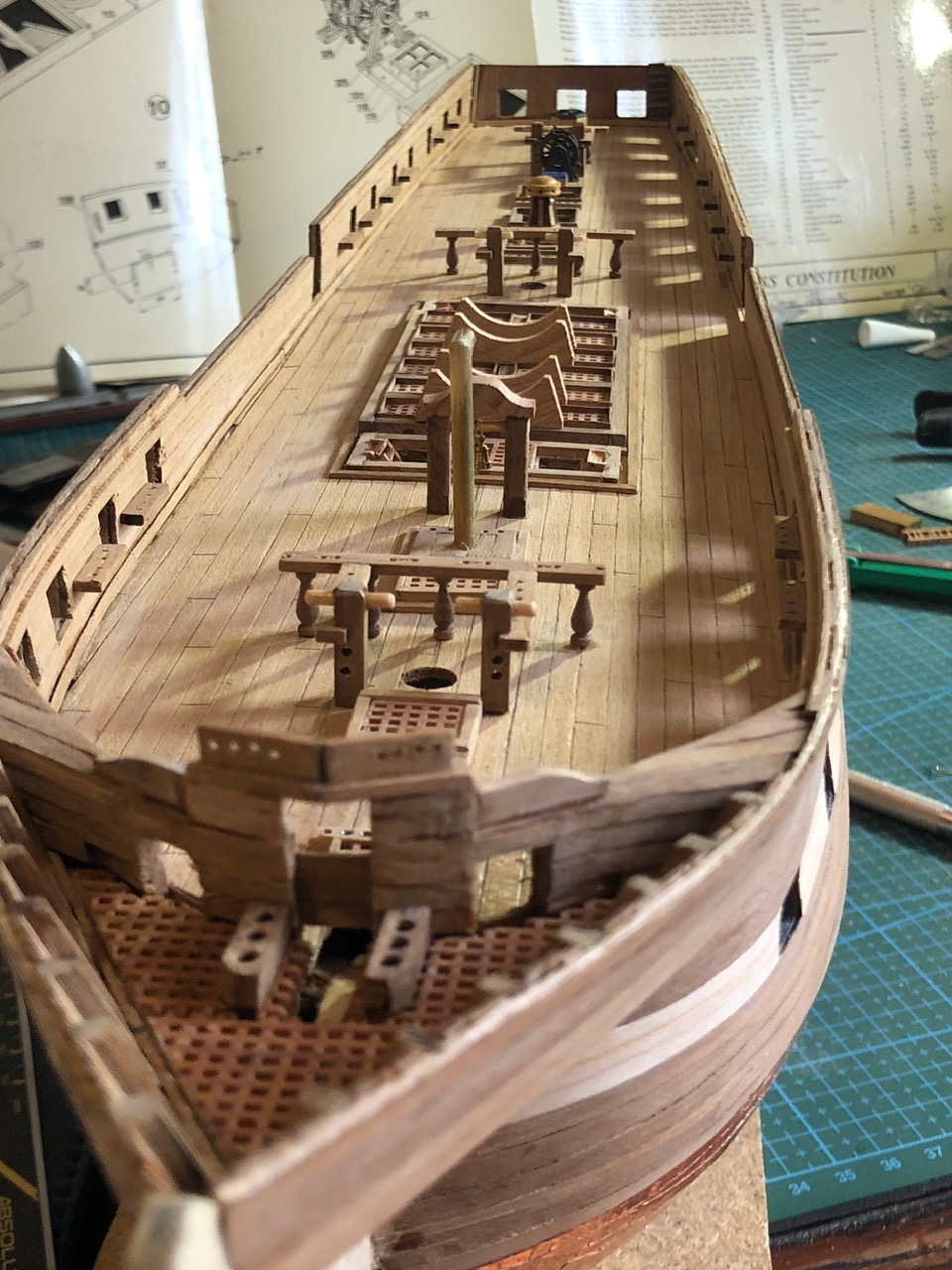
Here are some shots of the current stage.
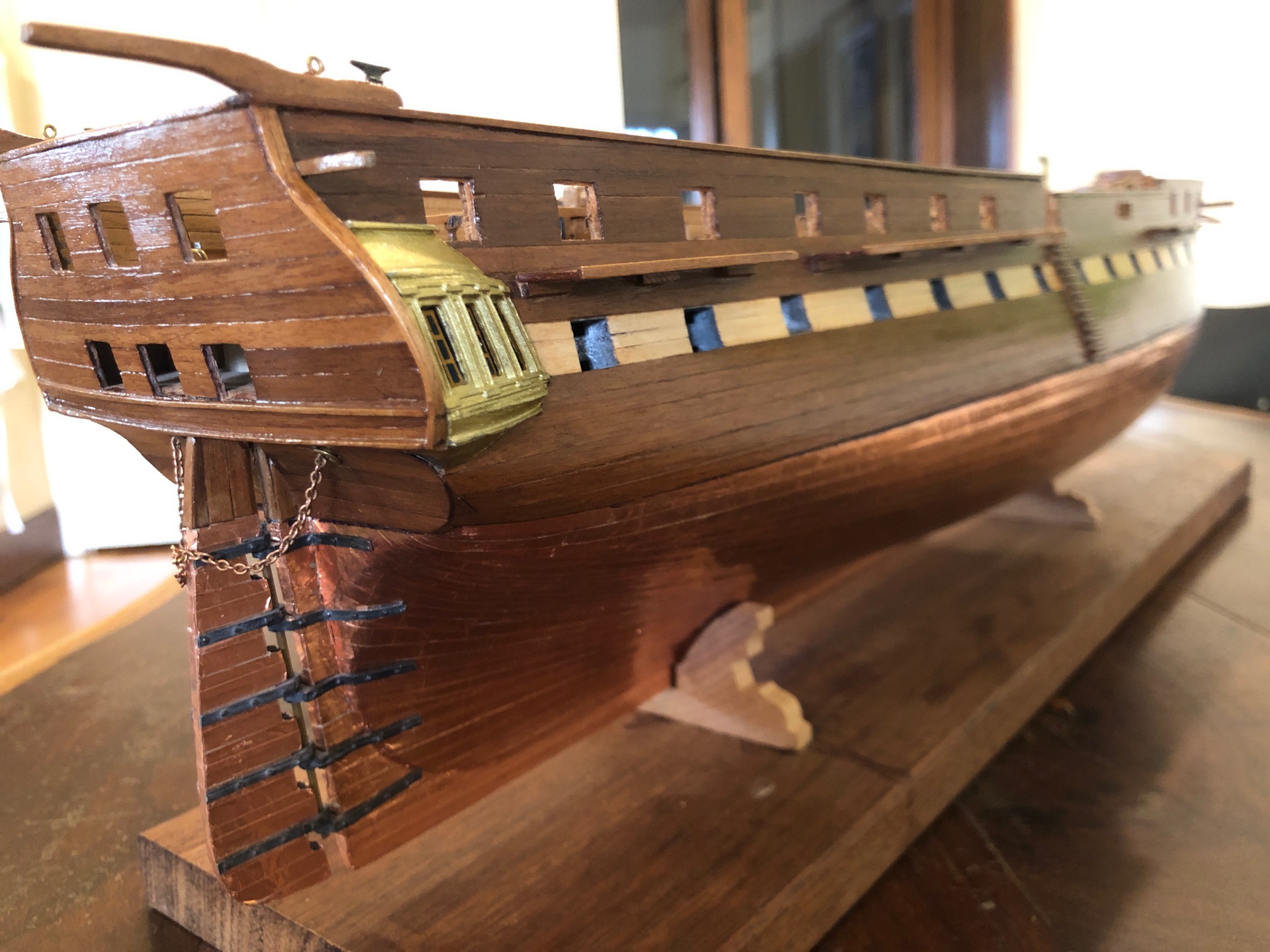
Now I can start gluing on parts such as the name plate, stars, stern eagle, and prow.
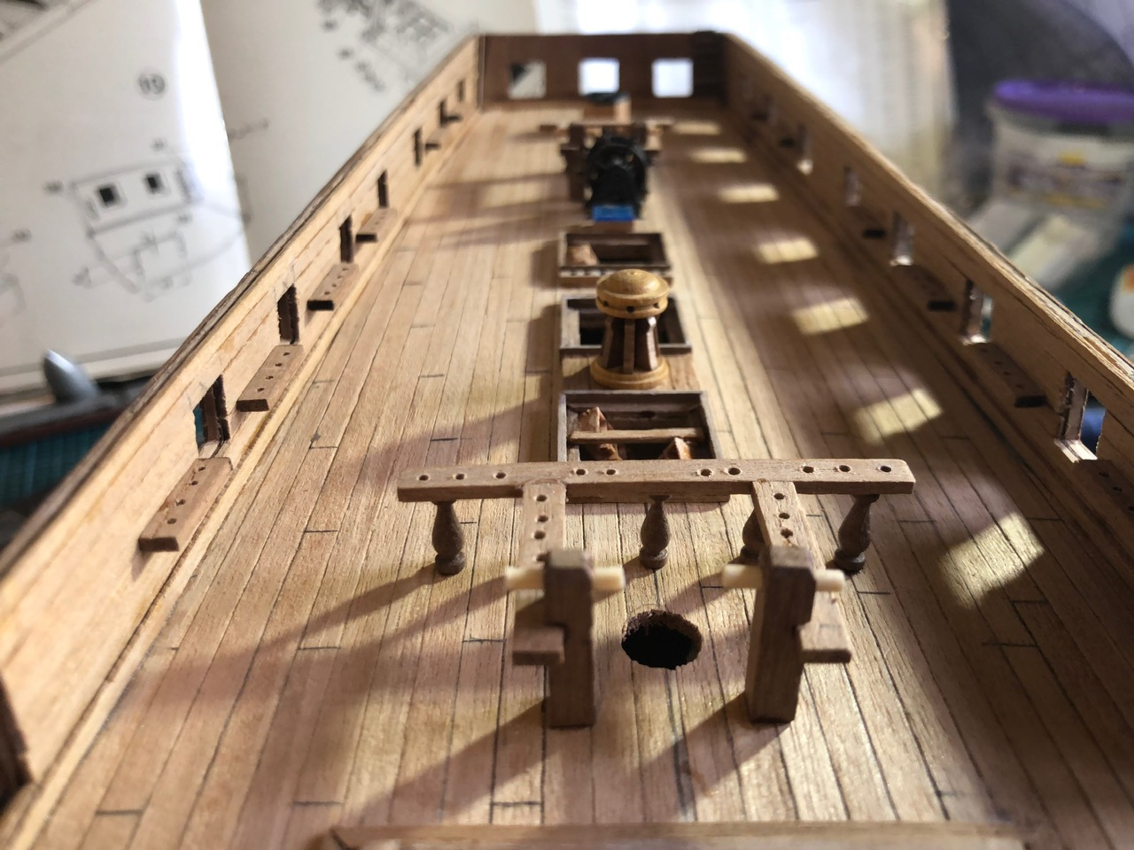
This model has 50 guns! There are 30 on the gun deck, 18 carronades on the top deck, and 2 long guns on the top deck. The long gun barrels are quite nicely cast metal with a bronze finish. But the bore was only a few mm deep. So I did a boring job….

July 17, 2024
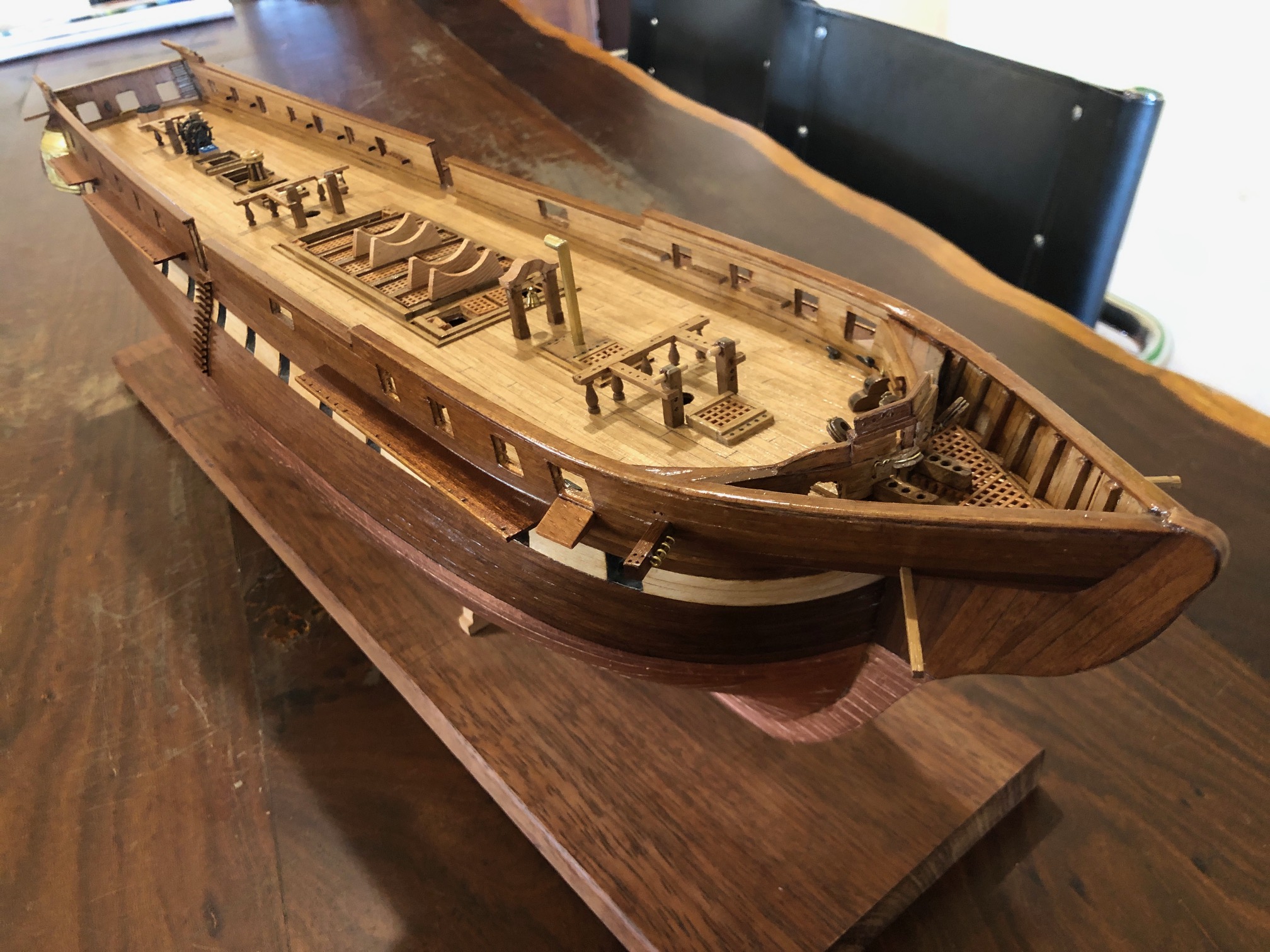
USS Constitution. Hull Progress.
Sorry, people. No posts for 3 weeks. I have actually been putting a lot of time into the hull of the constitution model, and this post will fill in some of the gaps. I must say that the lack of reader feedback about the previous posts has been a disincentive for me to spending time on further posts, but I have been told that it is now more difficult for my readers to post comments. I am unsure what has changed with WordPress, but it is frustrating for me. Feedback/communication with my readers is what drives me to write and post about what I am doing. I think that you have to register your email with WordPress to post comments. Free, but annoying. But please do it if you want these posts to continue.

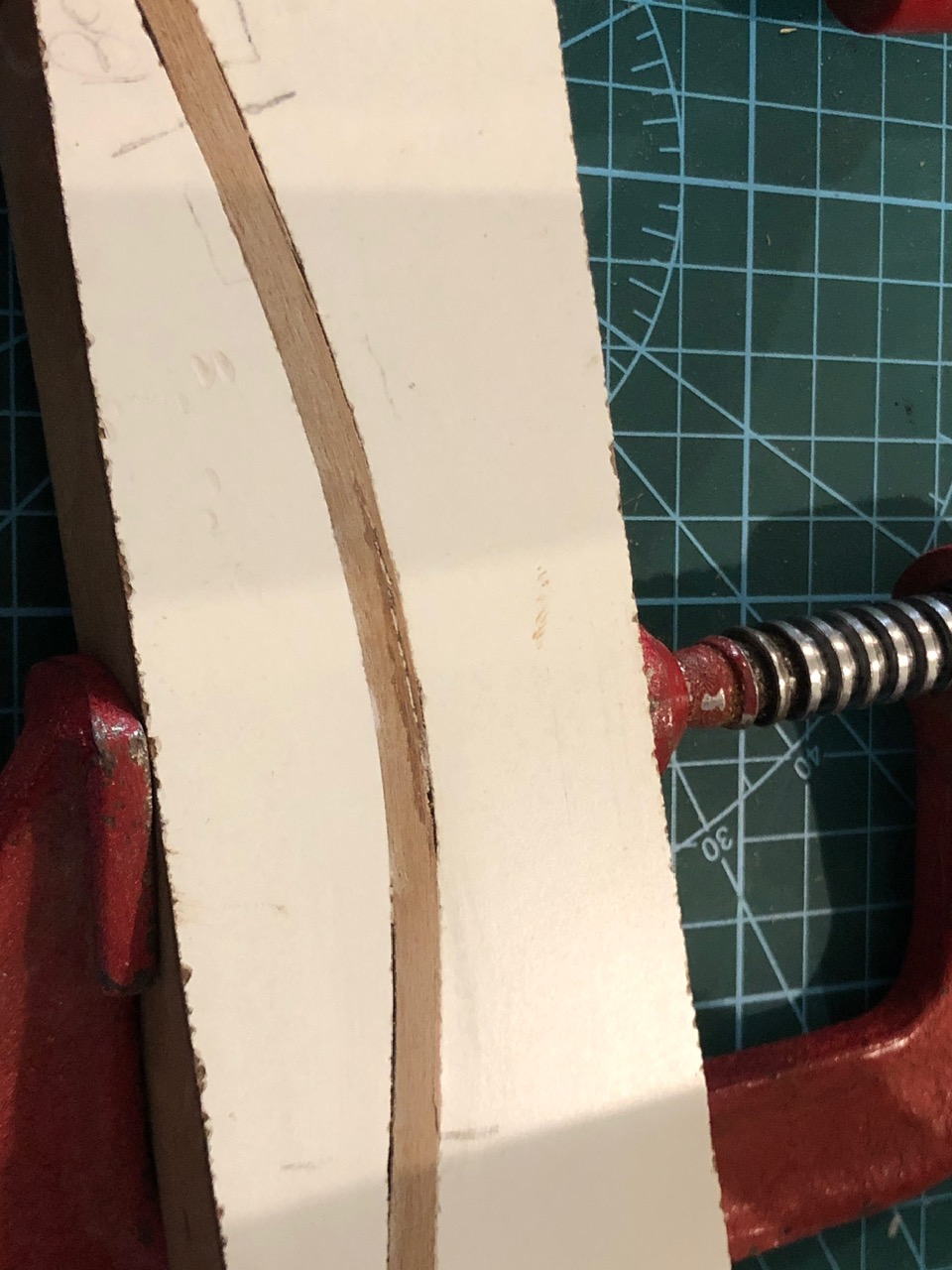
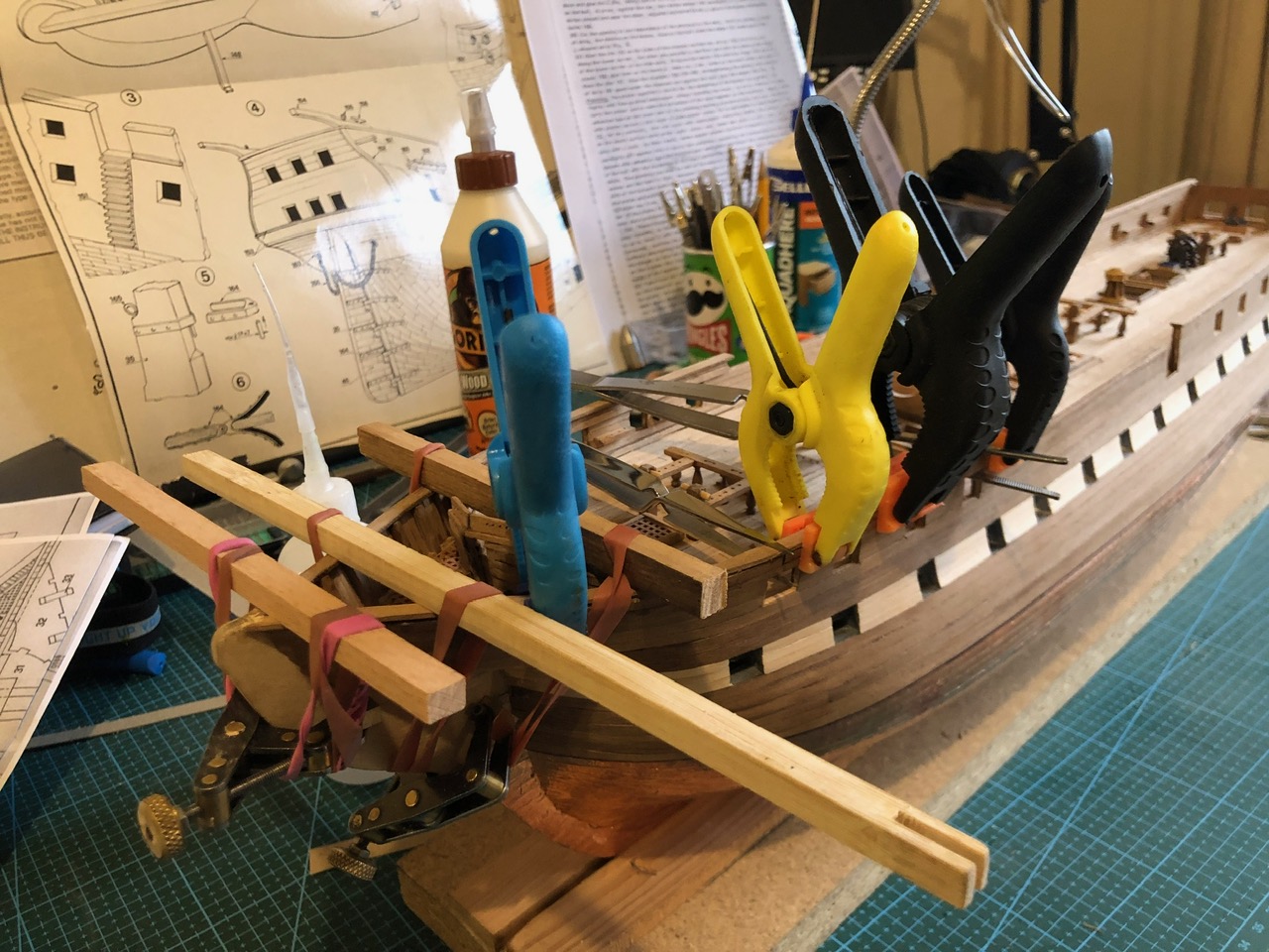
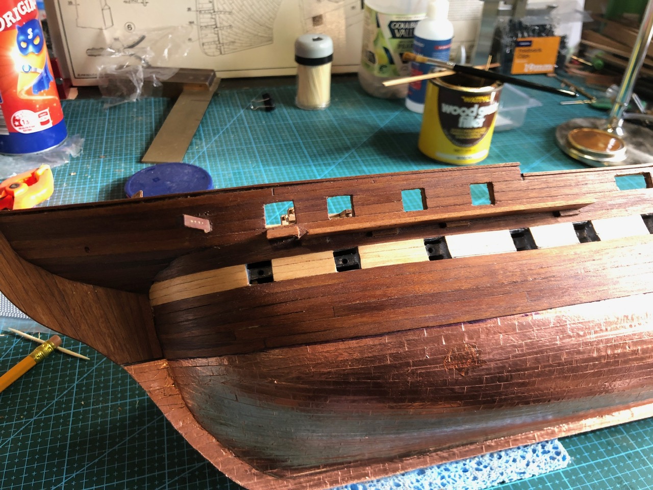
So, the hull is almost finished. 90% of the original ship cost. I still have to coat the deck planking, assemble the 50 odd cannons and carronades, and do the rigging. But I reckon about 50% of the build done?
April 18, 2024
Google Lens.
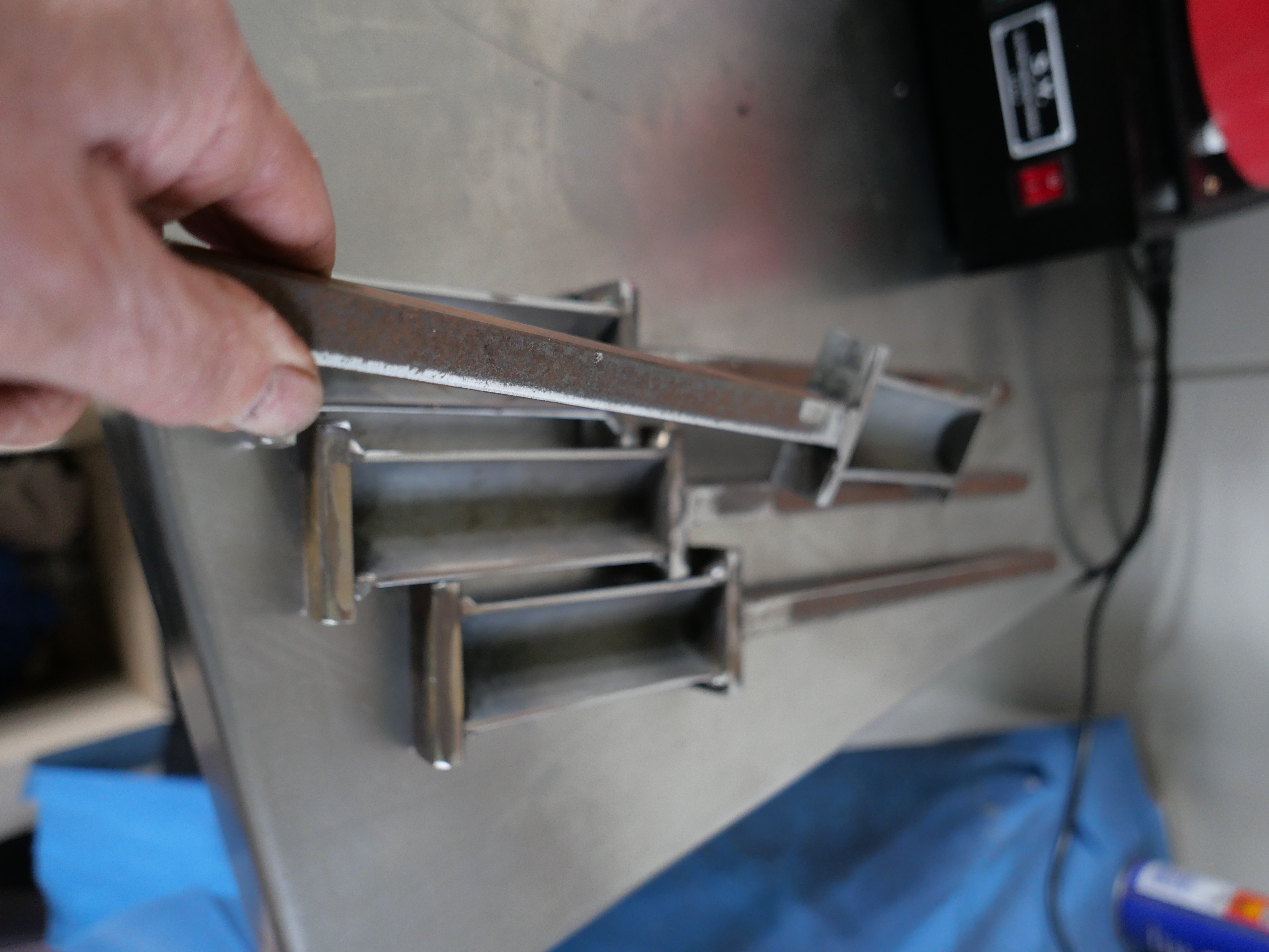
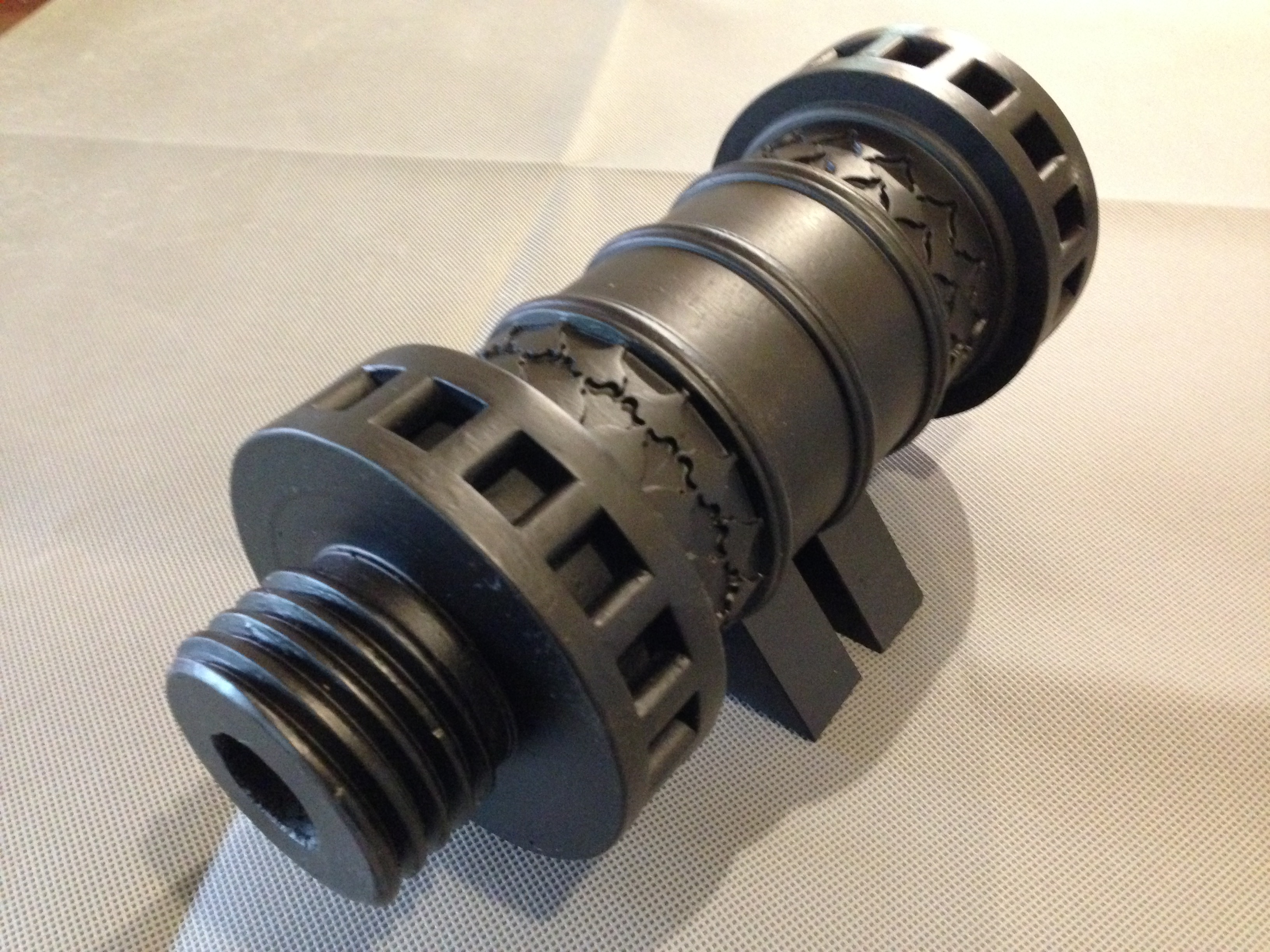
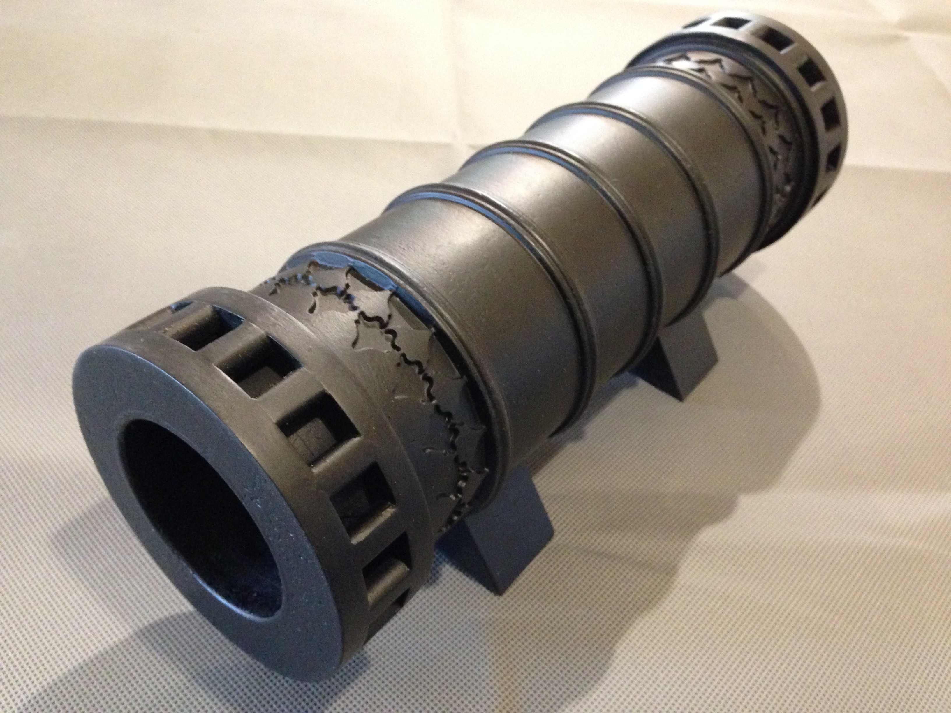
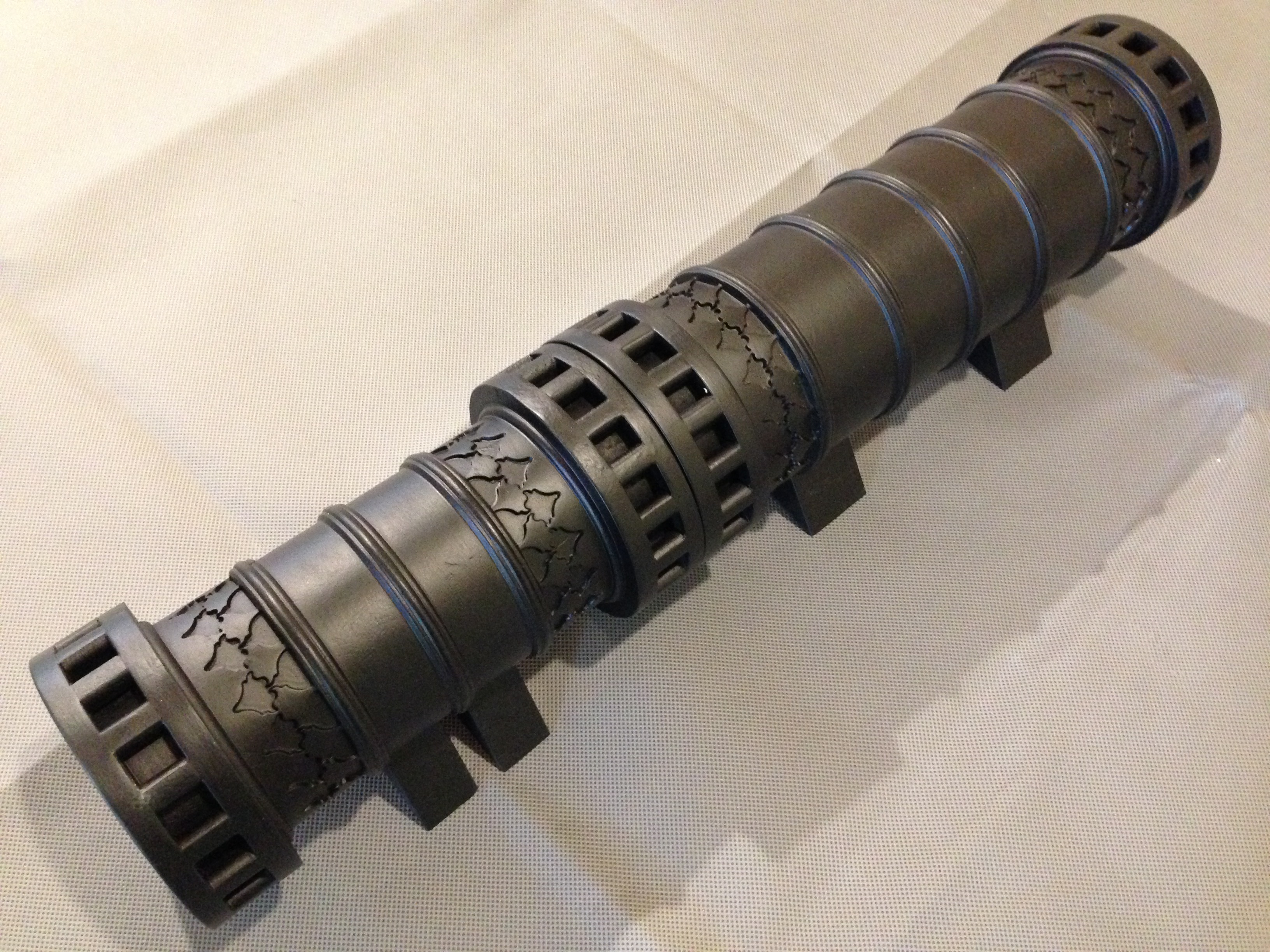
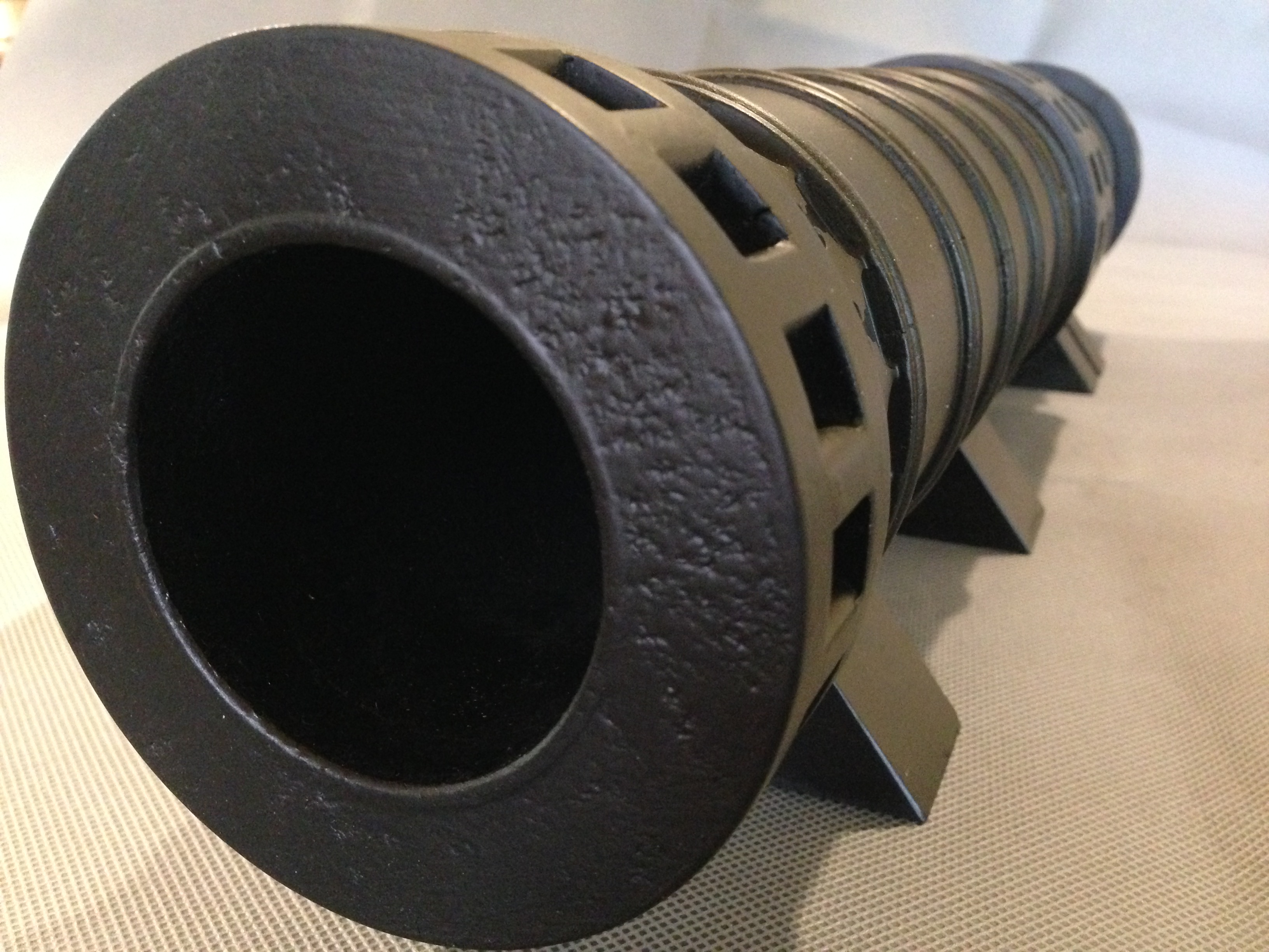
My farm neighbour handed me this tool which had come into his hands, saying “you’re a smart young fella, what is this for?” (He is 86 or thereabouts).
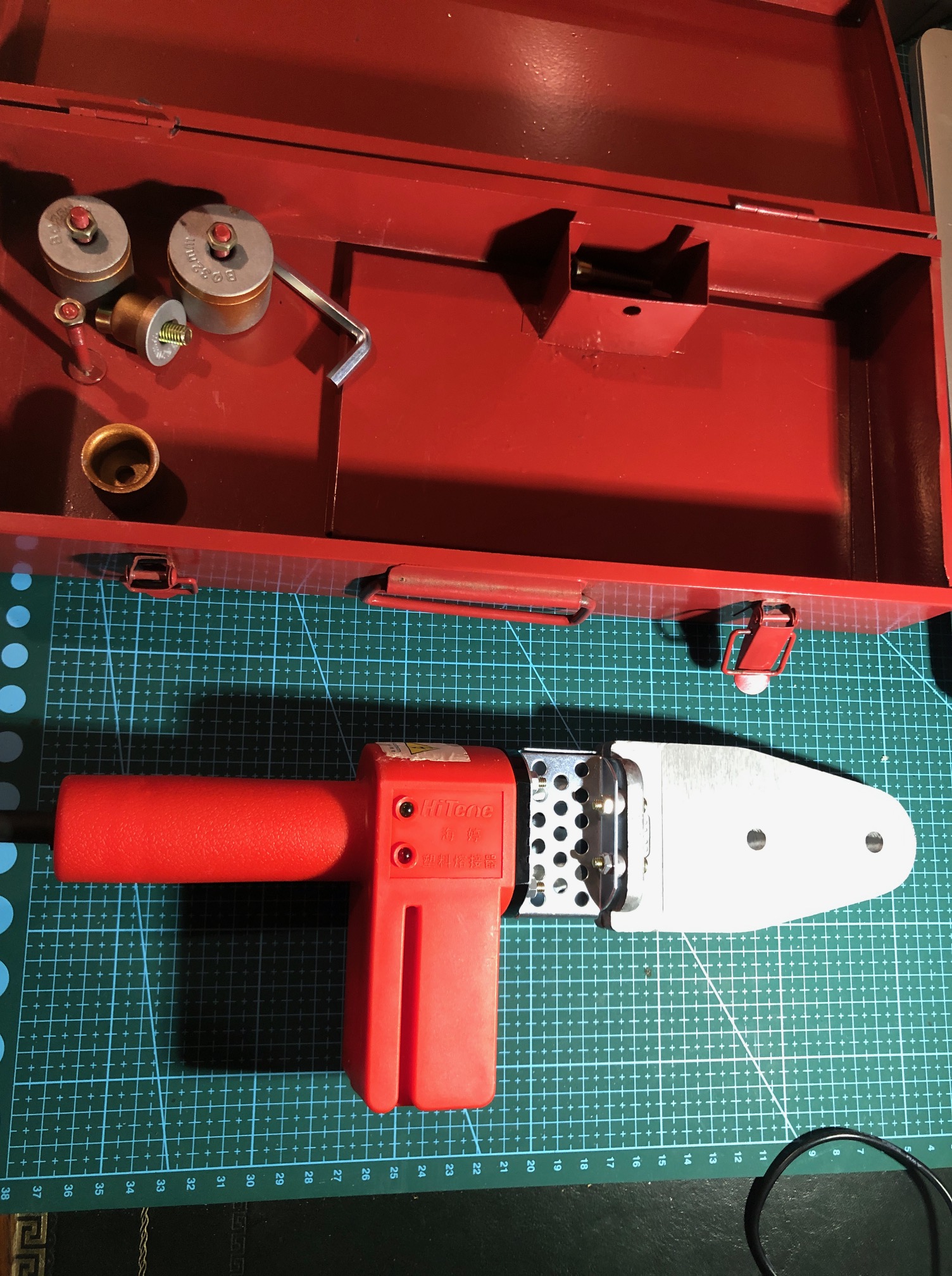
So I inspected it, confident that I could work it out.
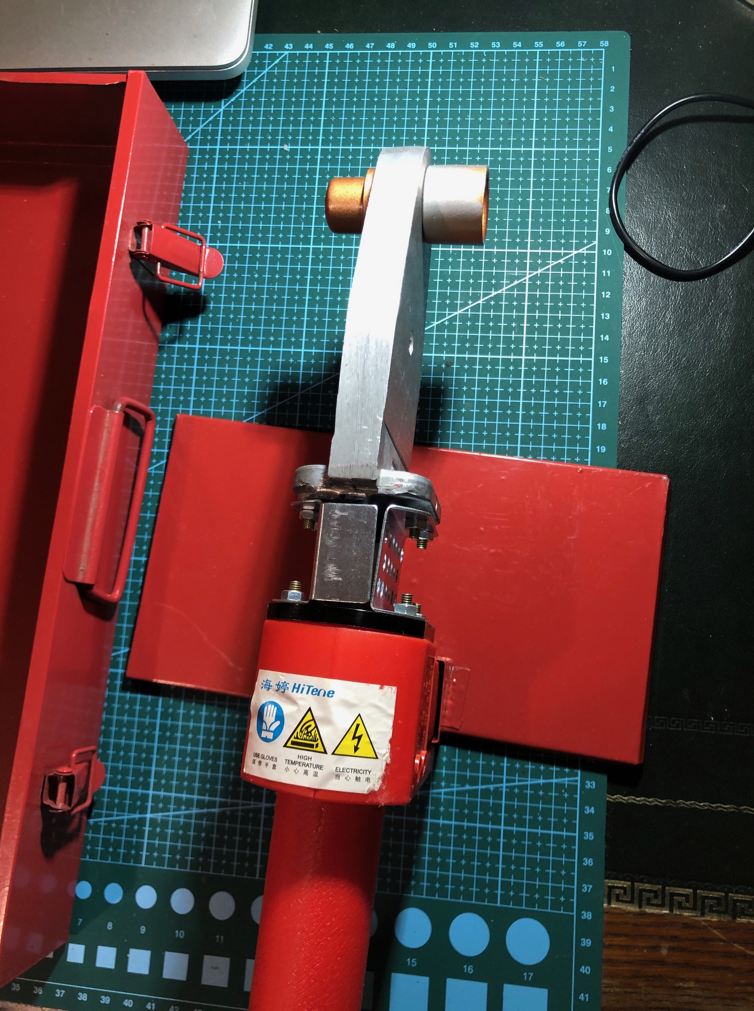
Works off mains power, with a large aluminium heating plate. But what are those bolt on cylinders for?
Could it be a bending apparatus for plastic?
I did not know, so I took it to our next “Model and Experimental Engineers” meeting, handed it around, and asked for assessments, hoping that someone would have the answer. Most of the 15-20 members present had no idea. But a couple of guesses came close.
Then one said…. “I know. I will ask Google Lens.”
“What is that”? I said.
He used his smart phone, took a photo of the tool with Google Lens (of which I was totally unaware), and showed me and the rest of the amazed meeting the answer…..

Almost identical to our tool.
It is a machine for joining plastic pipes using heat to melt and weld the surfaces, and costs $AUD 24 – $71, depending on brand and options.
Well!
That was astounding. Asking your smart phone to identify an unknown tool, instantly and accurately, and showing where to buy it, and at what cost!!!! And not just tools…. anything!!
It is obvious that I am not up to date. And VERY impressed. With the tool, its price, and possible applications. But mainly with Google Lens.
At home I tried it on the TV, and an 1866 model cannon which I had made. It showed the TV screen amongst several options. It showed a photo of the model cannon, which I had posted on this site some years ago, and listed this site as the source, with no price, which is accurate because it is not for sale.
Amazing!
SO TRY GOOGLE LENS! It is free. Works on smart phones and computers. You take a photo using Google Lens, or use an existing photo, and the program does its best to match the photo with the closest images it can find. With remarkable accuracy on my PC and iphone.
BTW. After a year of relative inactivity in the workshop I have picked two items that I am interested in modelling. Not sure which to choose first, or even whether to work on both. More details later.
May 30, 2020
Getting Ready for Casting
Setting up for casting molten metals into shapes for my model Armstrong cannon. Still getting ready.
Today I made some moulds for dealing with any left over metal melt. Not a big deal, but it does have to be done before the first melt. No point realising that there is nowhere to put the left over aluminium or bronze during the pour. It has to go somewhere.
So today I made some ingot moulds, in readiness.
The ends of the moulds are sloped to allow easy ejection of solidified aluminium or bronze.
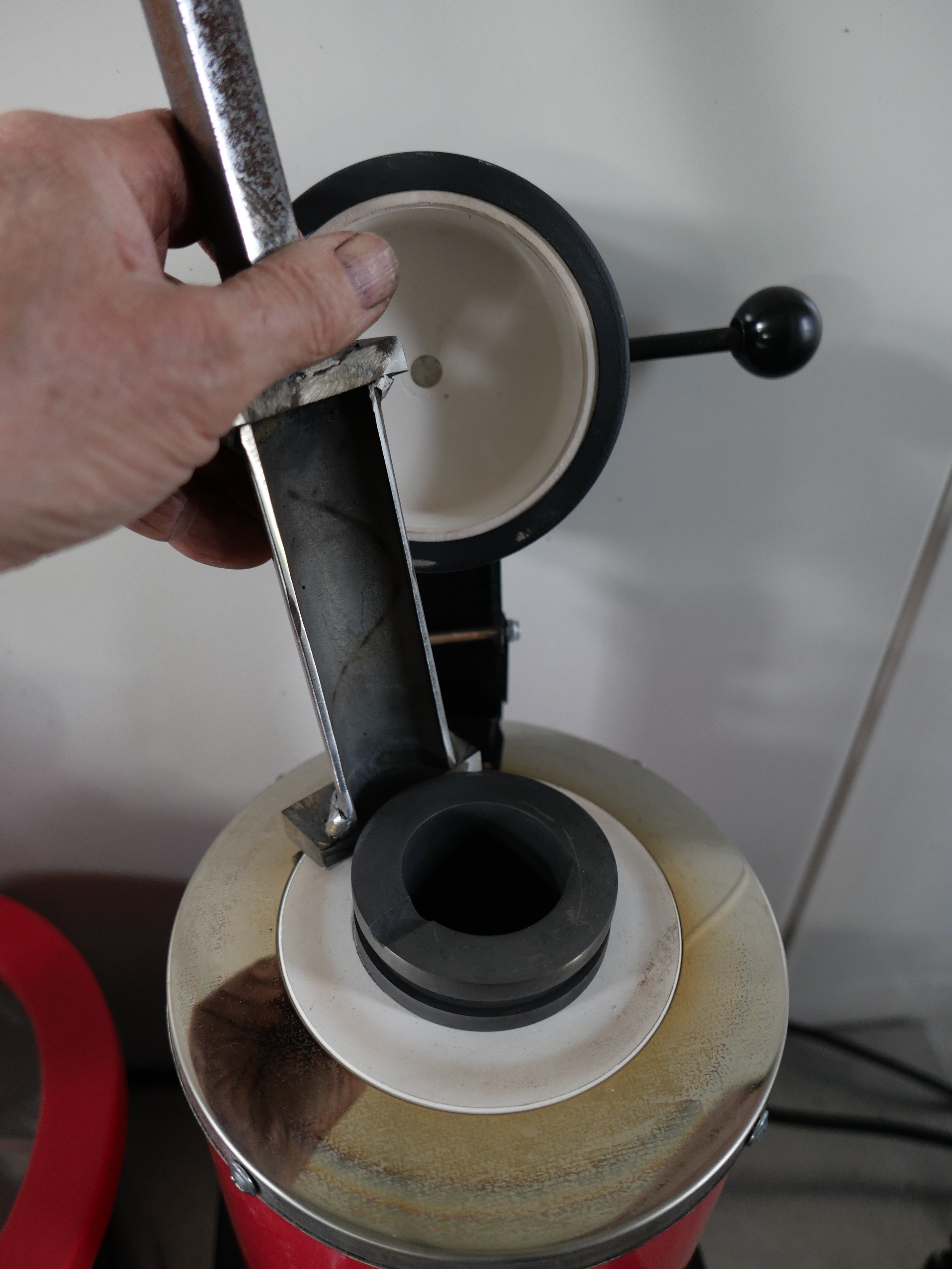
4 ingot moulds. Made from 40mm ID thick wall pipe, with long handles. The diameter of my crucible is 48mm ID, so any ingots made should fit into my crucible later for remelting.
It seems a long time since I have done any welding, and the welding of these items was pretty ordinary. But the joins seem water tight, so hopefully they will be OK.
Today I fired up the casting oven, to 850ºC, and the load was some ordinary food tins. They are the correct diameter for investment moulds. I wanted to see if the tins would cope with these temperatures. (after removing labels of course).

3 ordinary food tins, at 850ºC.
It became apparent, that the tin joins were welded not soldered. And the inside and outsides of the tins were covered with some sort of paint or plastic, because it flaked off. But the metal cans remained intact. Admittedly, when hot they were VERY soft, but when cooled they retained their shape, and were quite stiff. I would be prepared to try these for single use moulding projects.
I have realised that my investment plaster mixing bowl is too big for the vacuum chamber which I had bought. So I have ordered another vacuum chamber, and waiting for it to arrive before starting a mix. I am using the delay to gather items like the ingot moulds above.
It will probably be another couple of weeks before I am ready to cast. Meanwhile my 2mm rivets have arrived at last, so I will get back to the riveting.
October 24, 2019
Thinking about future exhibitions….
Still recovering from The Royal Geelong Show, where my beam engine and the Trevithick dredger engine ran for ~8 hours per day for 4 days, and required almost constant supervision. I was very pleased that they did so without a problem.
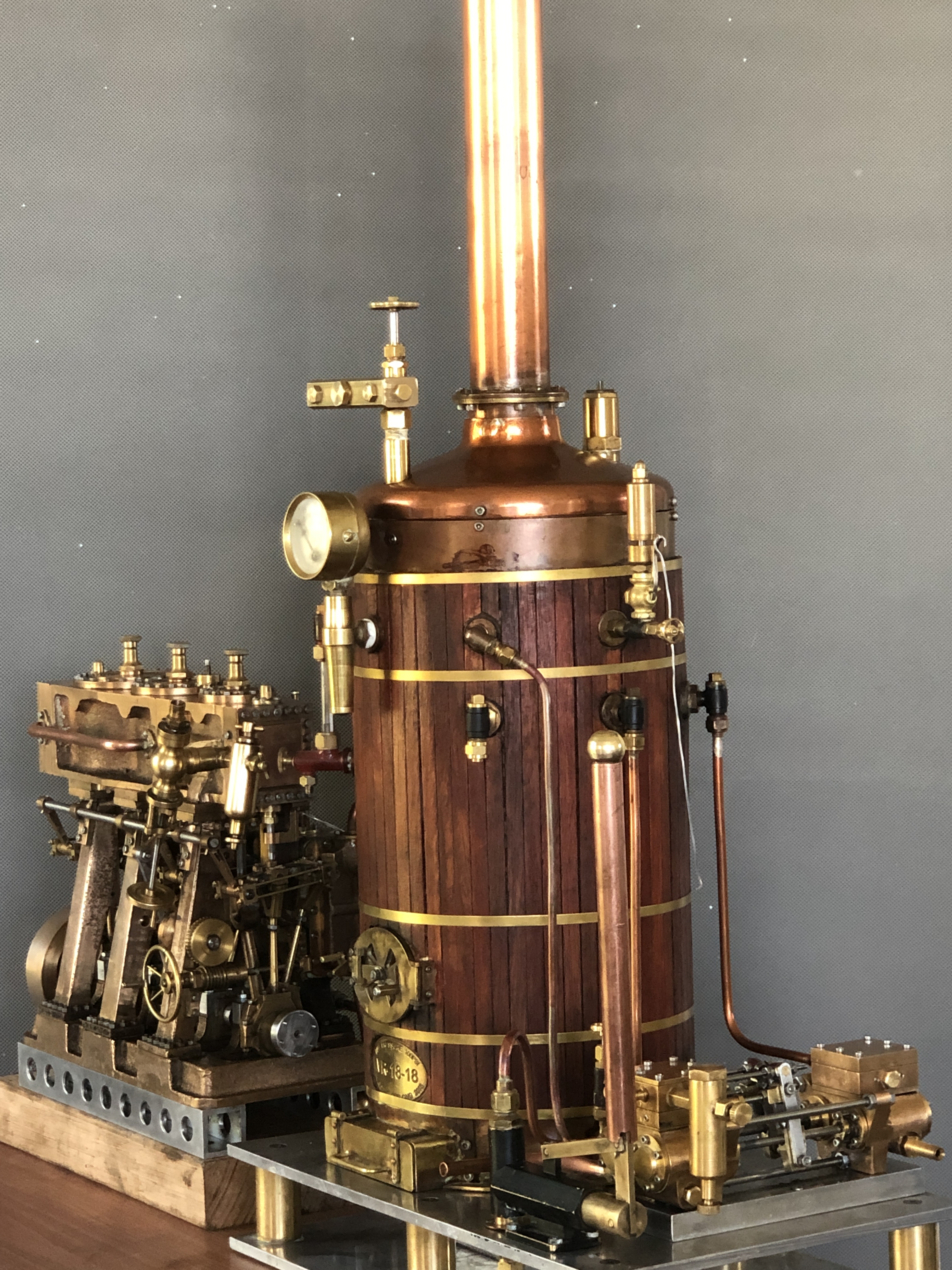
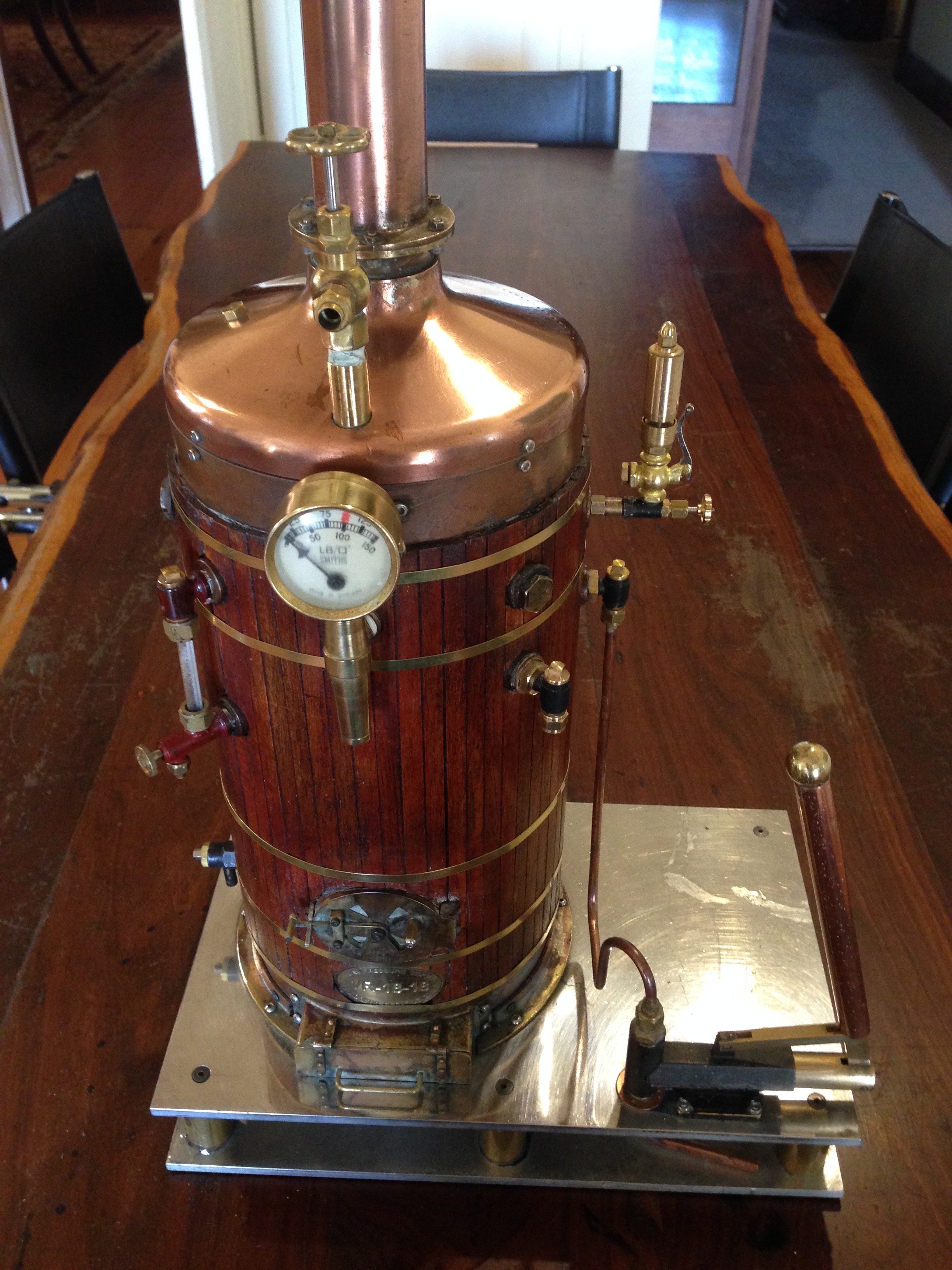
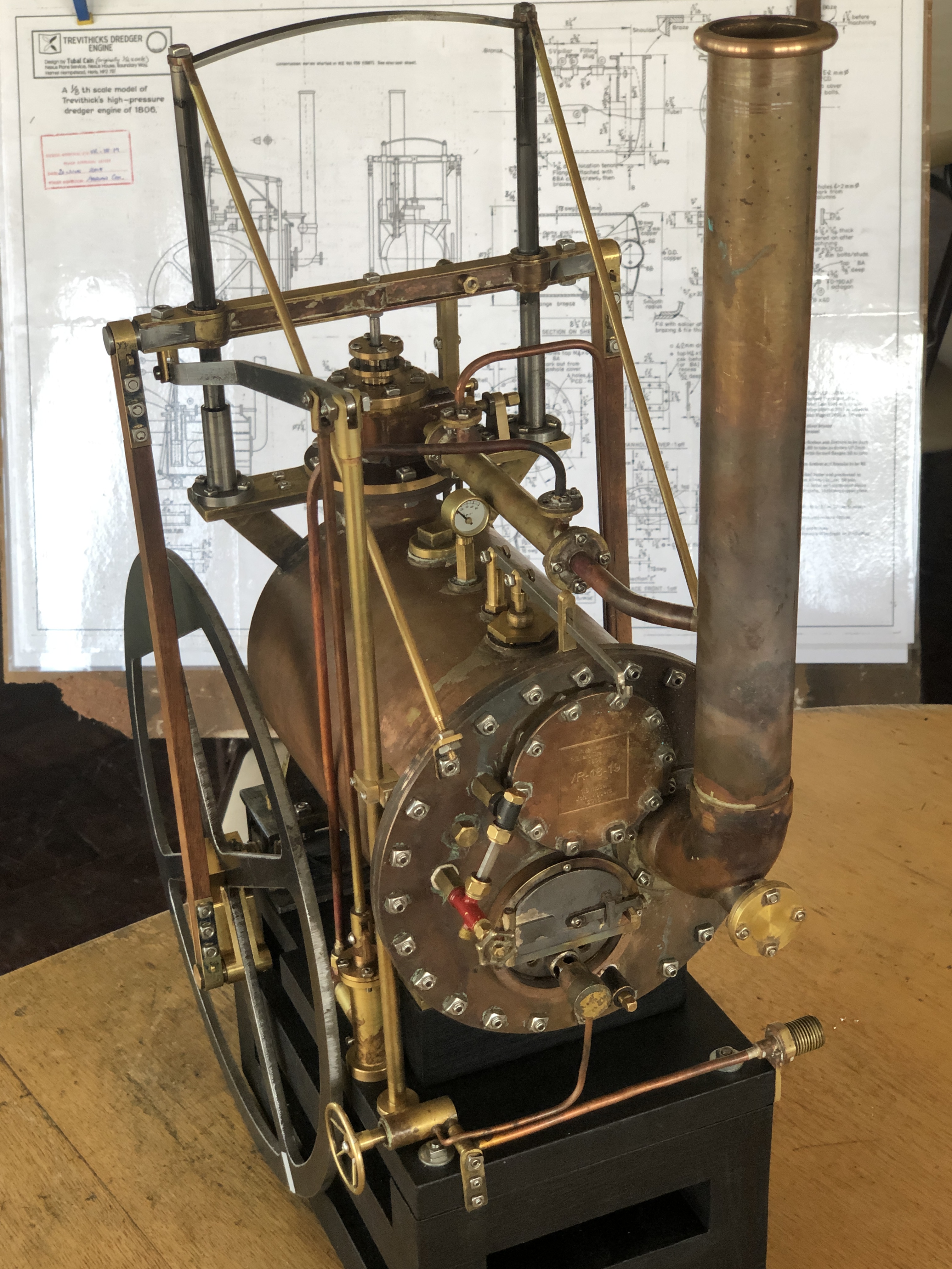
For future exhibitions I would like to also run the triple expansion steam engine using the vertical boiler, for which I recently made the Southworth boiler feed pump. And there are occasions where I might run the triple and the beam engine together from the vertical boiler. That arrangement will occupy a fair bit of bench space, and in this post I am considering options for the arrangement.
But first, I needed a steam outlet manifold to handle multiple engines, simultaneously, and hopefully to avoid a big tangle of pipes. Here is the manifold.
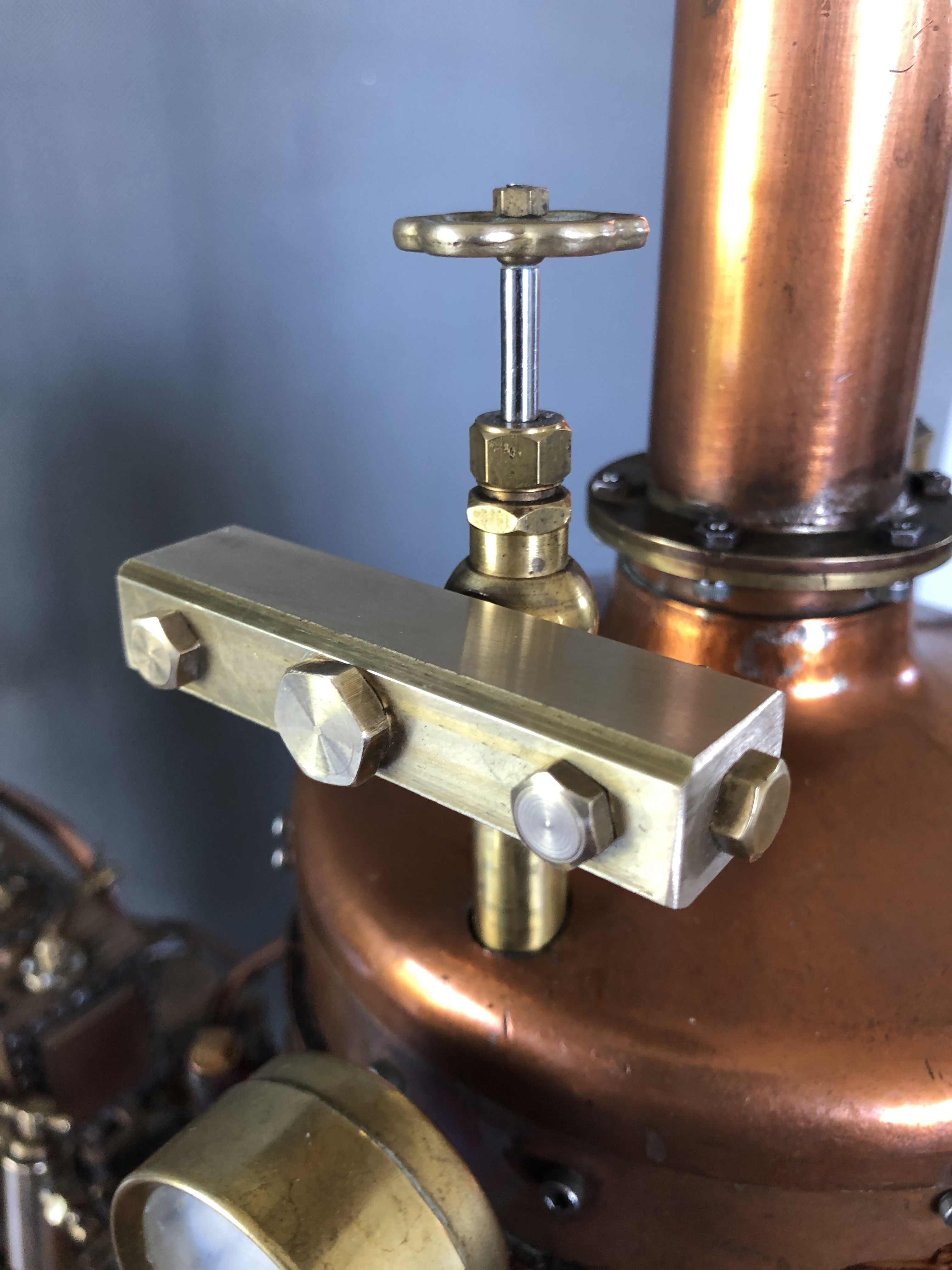
The manifold has 6 x ¼” outlets and one 3/8″ outlet.
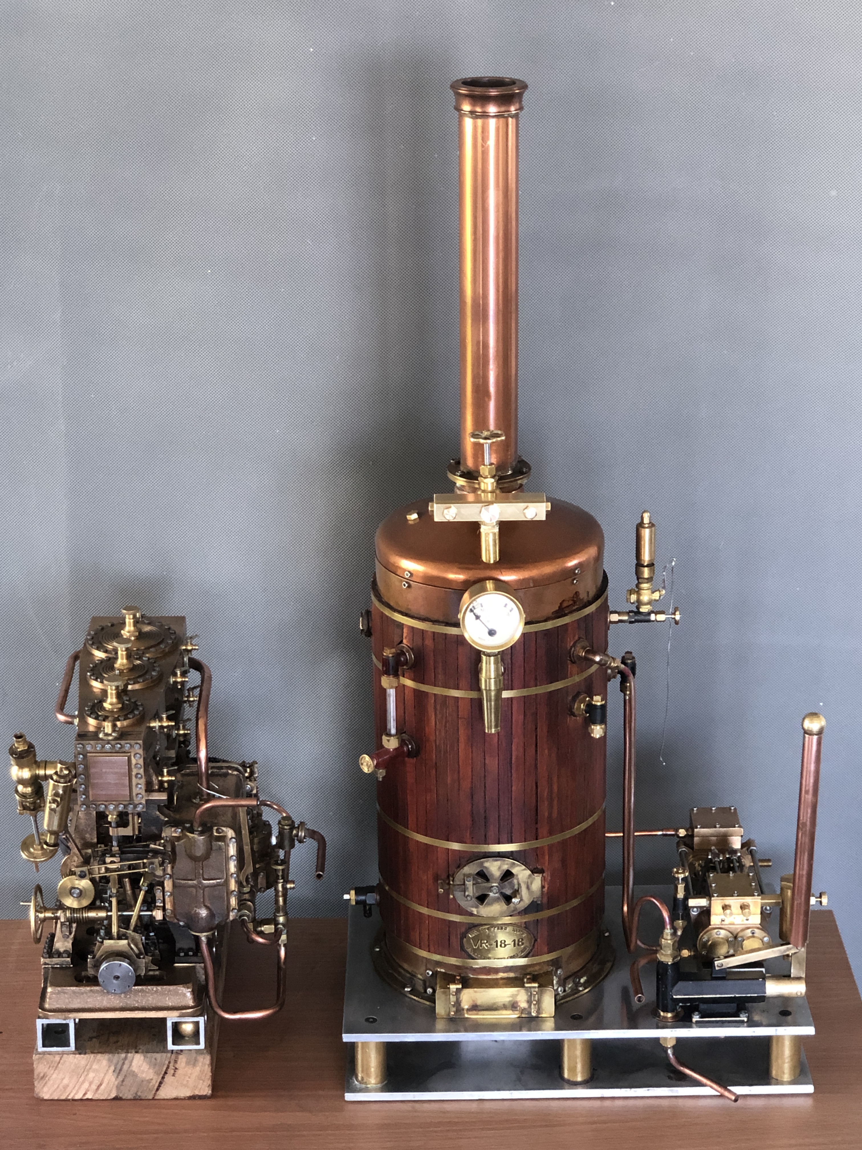
Option one lines up the boiler and engine like this….

Option two is more compact, but ?less appealing. Pics following..
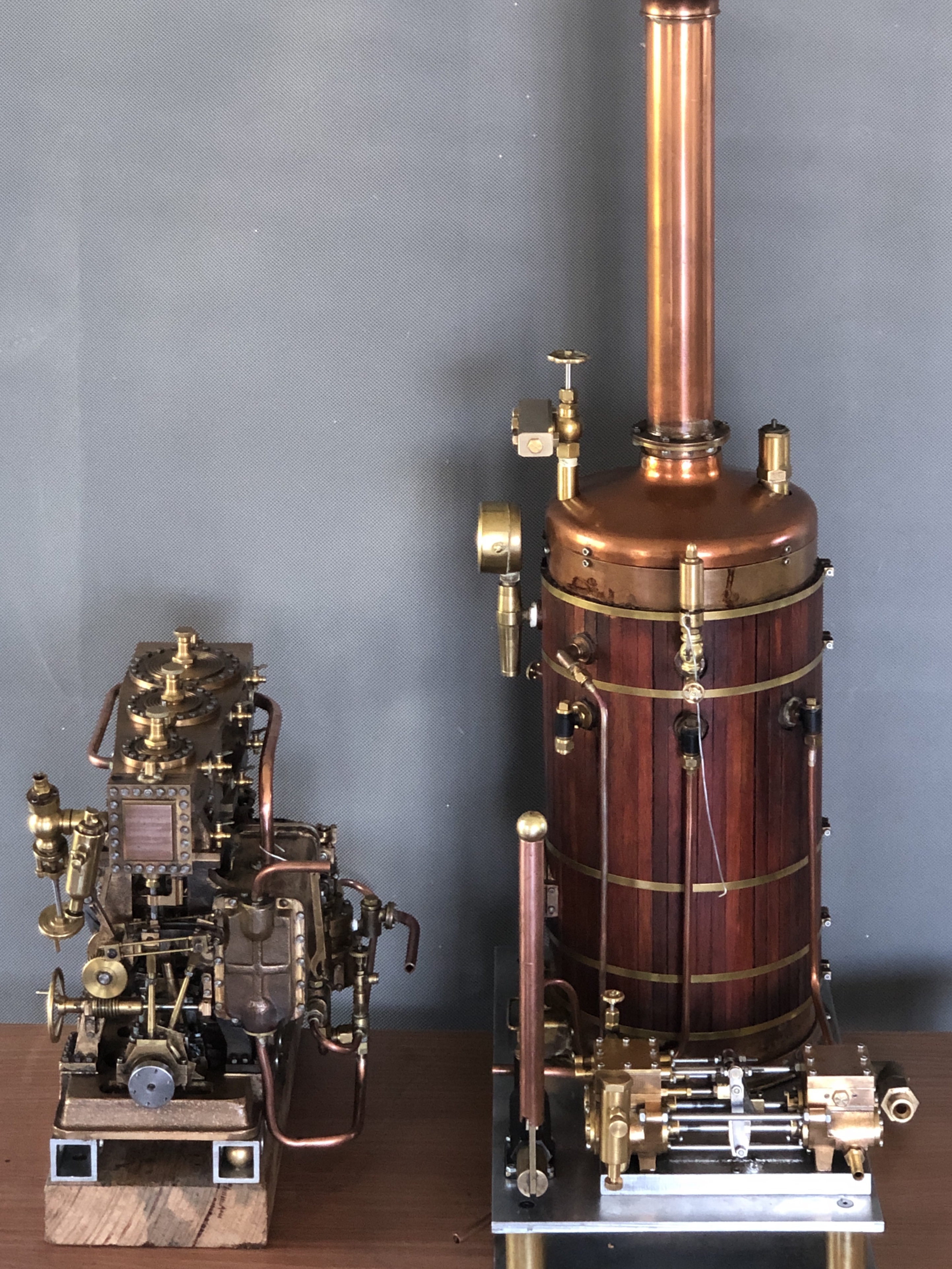
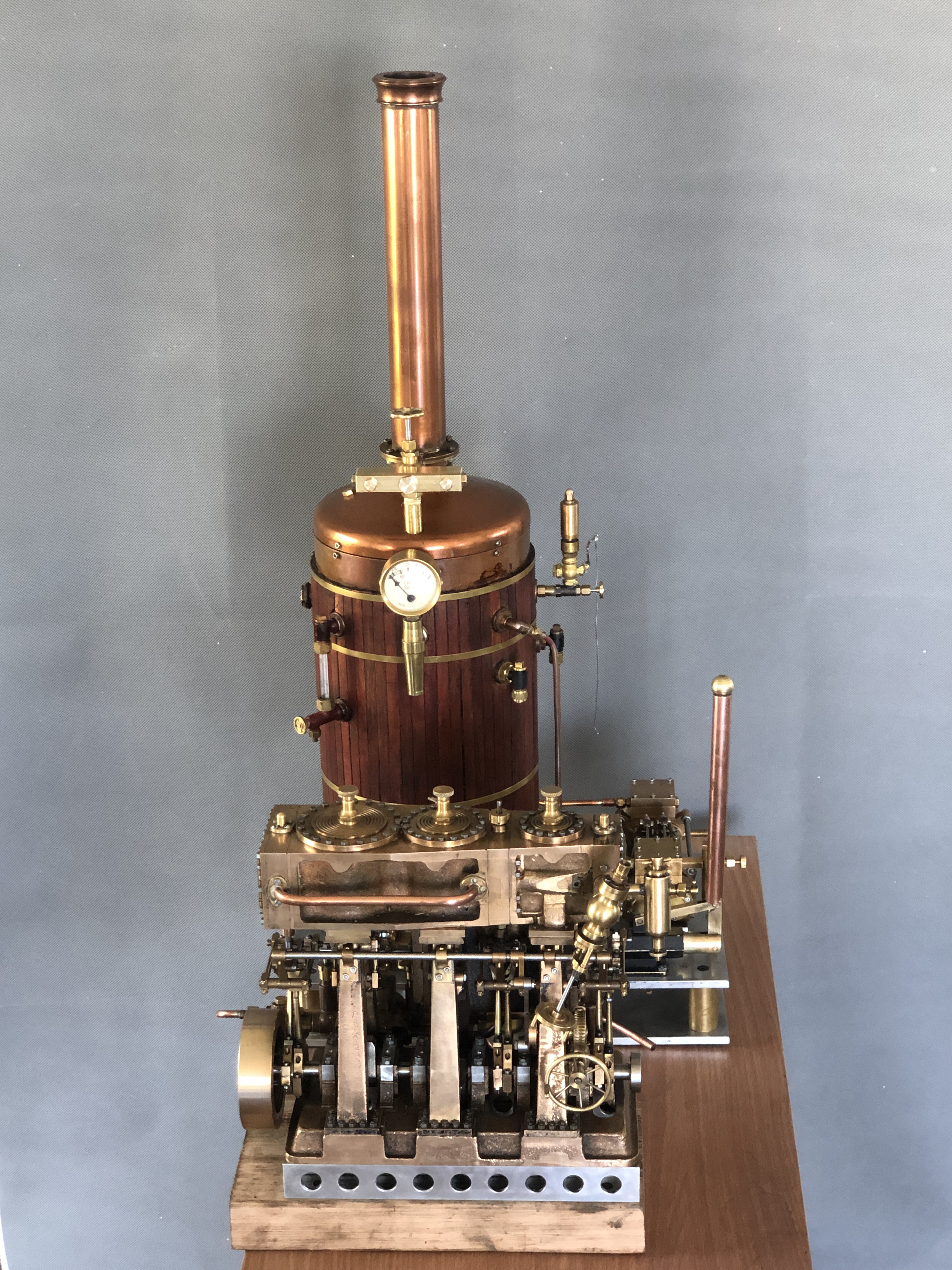
The lump of wood under the engine is temporary, just to give an idea of the heights.
OK, this post is just an excuse to show some pics. I have decided to go with option one. It is closer to the appearance if the boiler and engine were actually in a boat, and also will make it easier to add the beam engine to the right of the boiler if/when I run the two engines simultaneously.
And I doubt that I will be able to avoid a jumble of pipework. The triple has 6 pipes attached, the boiler has more, then there is the beam engine. And, I will need a water container from which to feed the boiler. That will be located behind the boiler. Still considering whether it should be a squarish box on a stand like the railway water towers, or a cylinder on a low stand. Any thoughts?
Quote | October 15, 2019
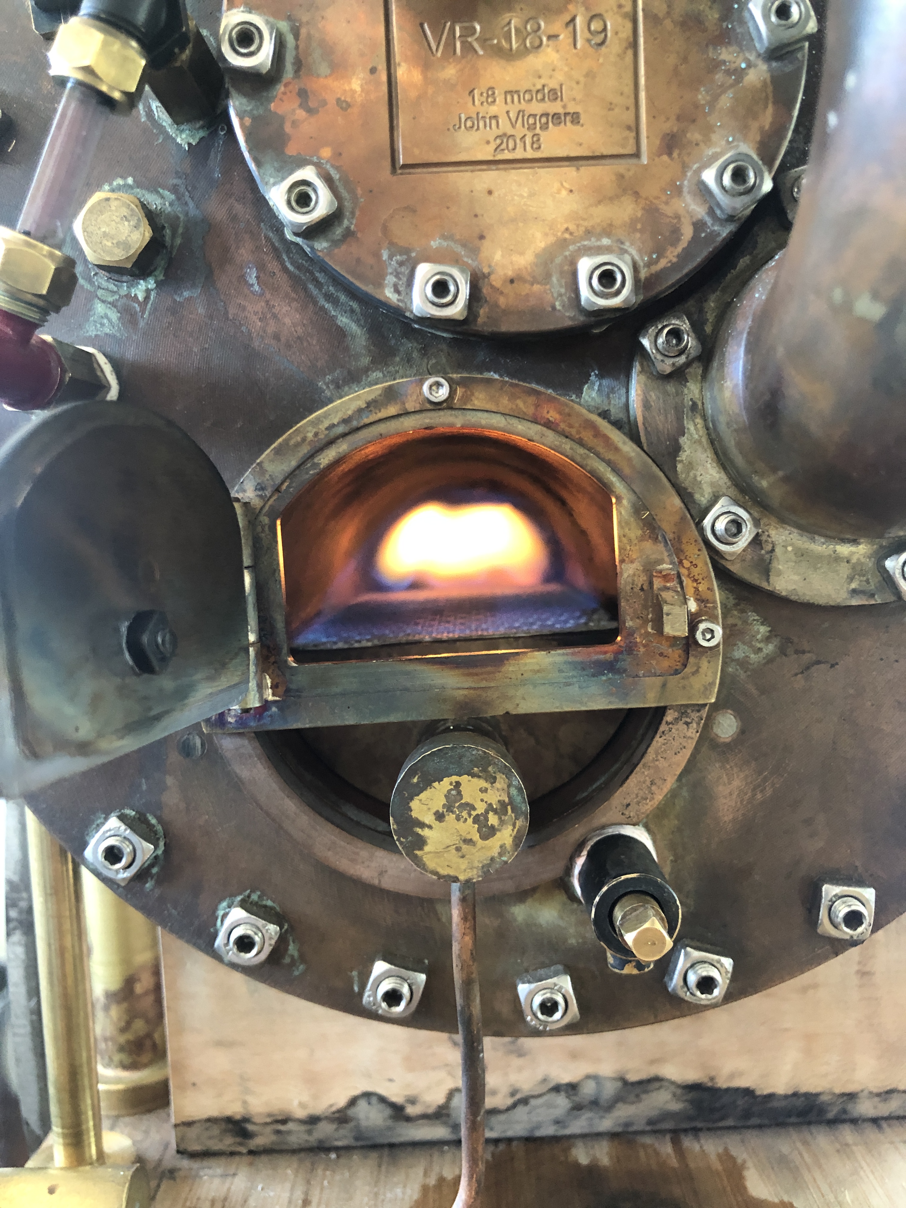
Boiler Feed Pump Pumping
Yesterday I reseated the pump valves, reassembled the pump, then tested it on steam.
Most of the following video has the boiler at only 25psi, but I did run it off camera at up to 75psi.
After making the video I redirected the exhaust steam from the pump into the firebox. It actually seemed to improve the gas flame, maybe by acting as a blower. Not so sure about this being permanent though, because the exhaust steam contains oil from the displacement oiler, and I dont want that oil to be deposited in the firetubes.
I will make a water tank to supply boiler water. Maybe the exhaust steam could be passed through a heat exchanger in the tank, so the boiler feed water is preheated.
(if the video is not showing, click on the https link below)
September 27, 2019
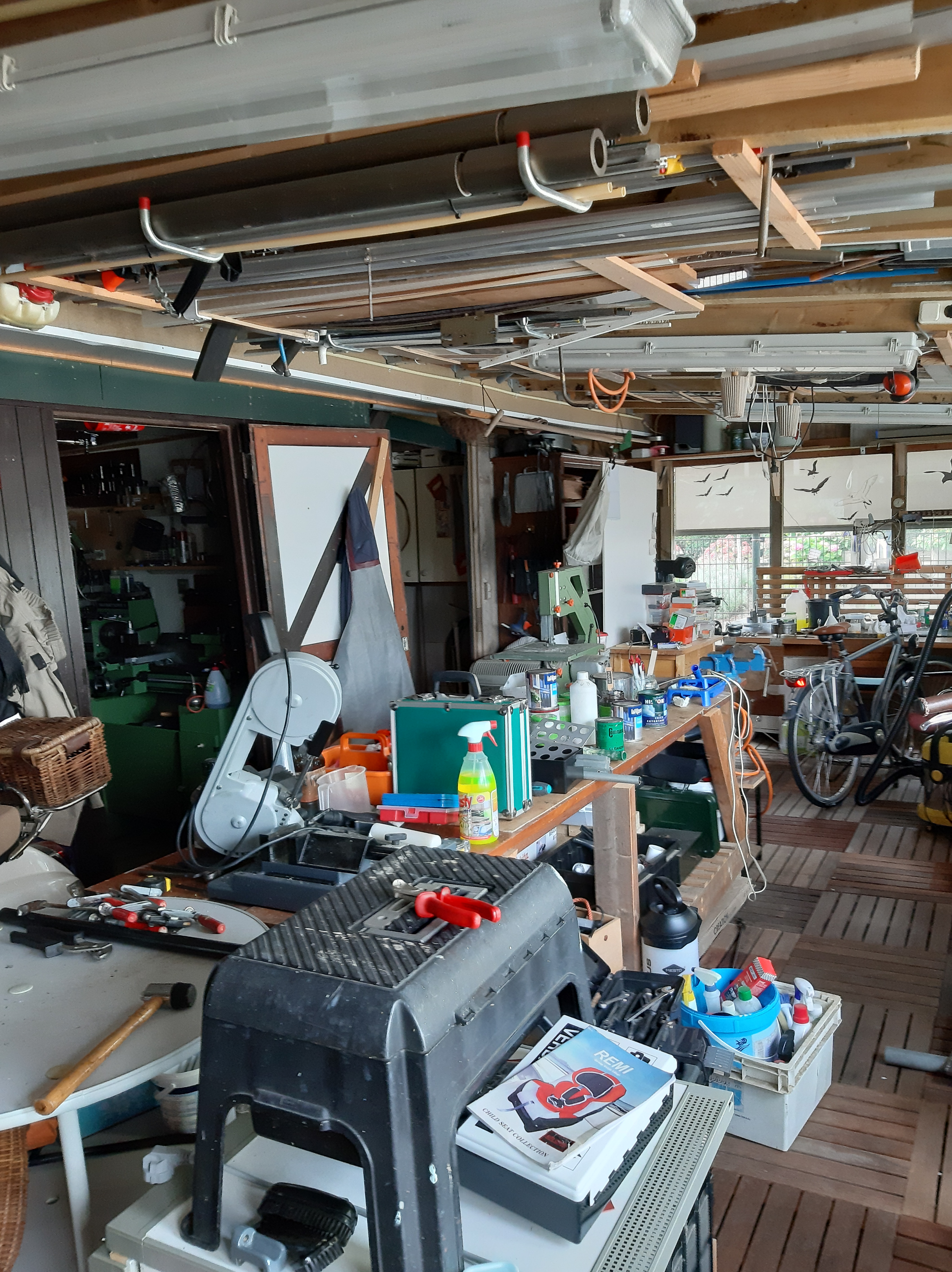
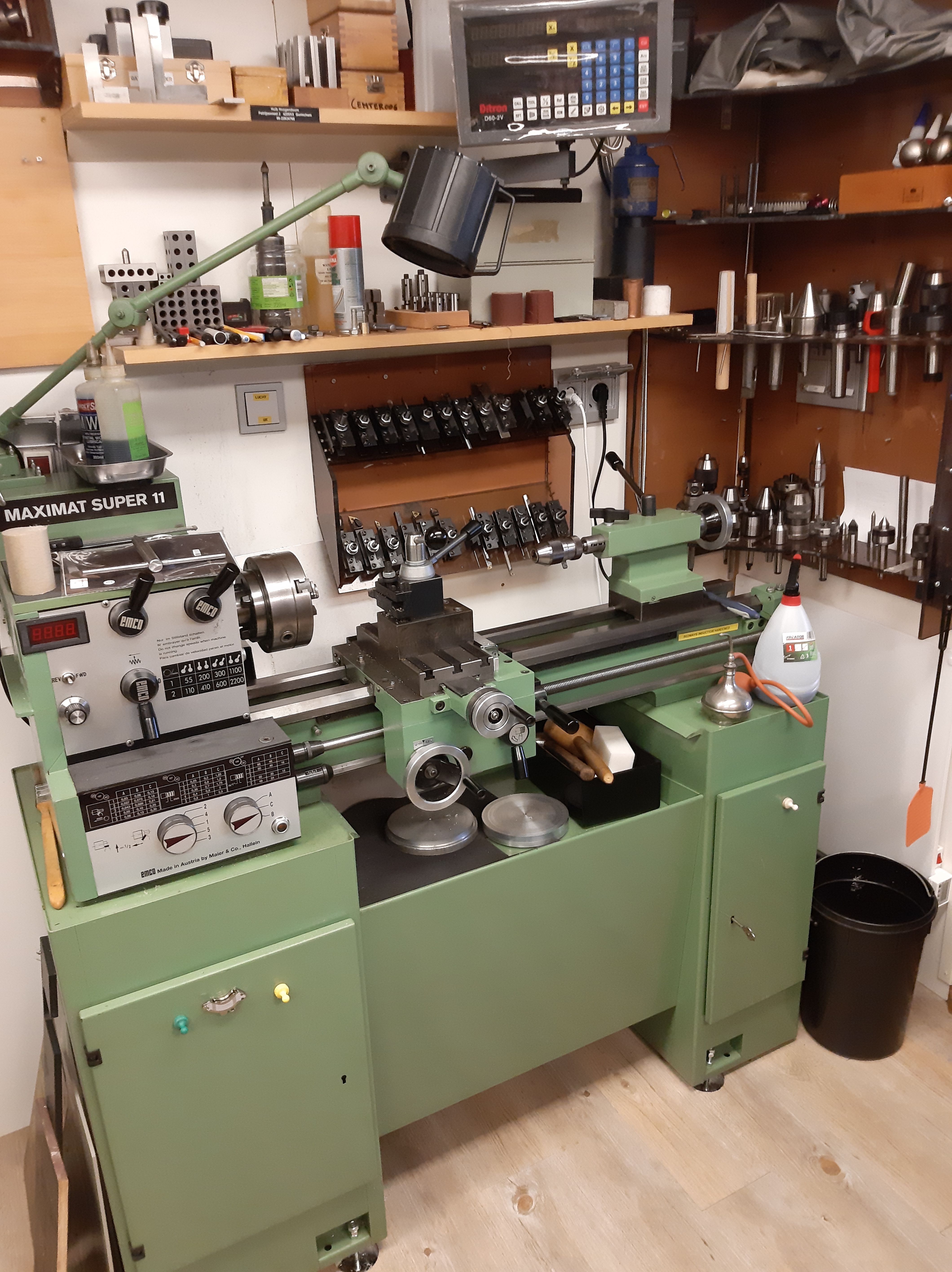
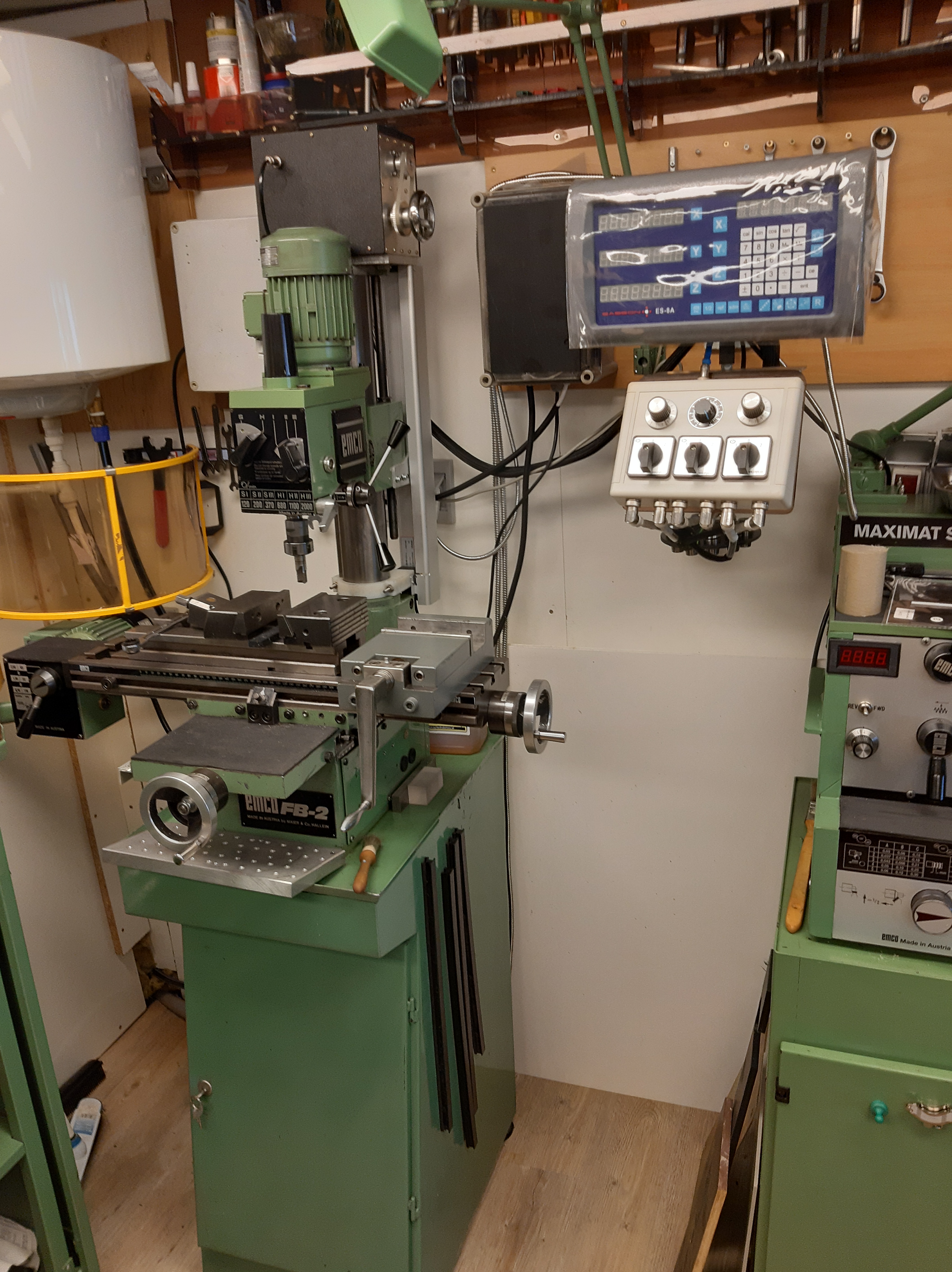
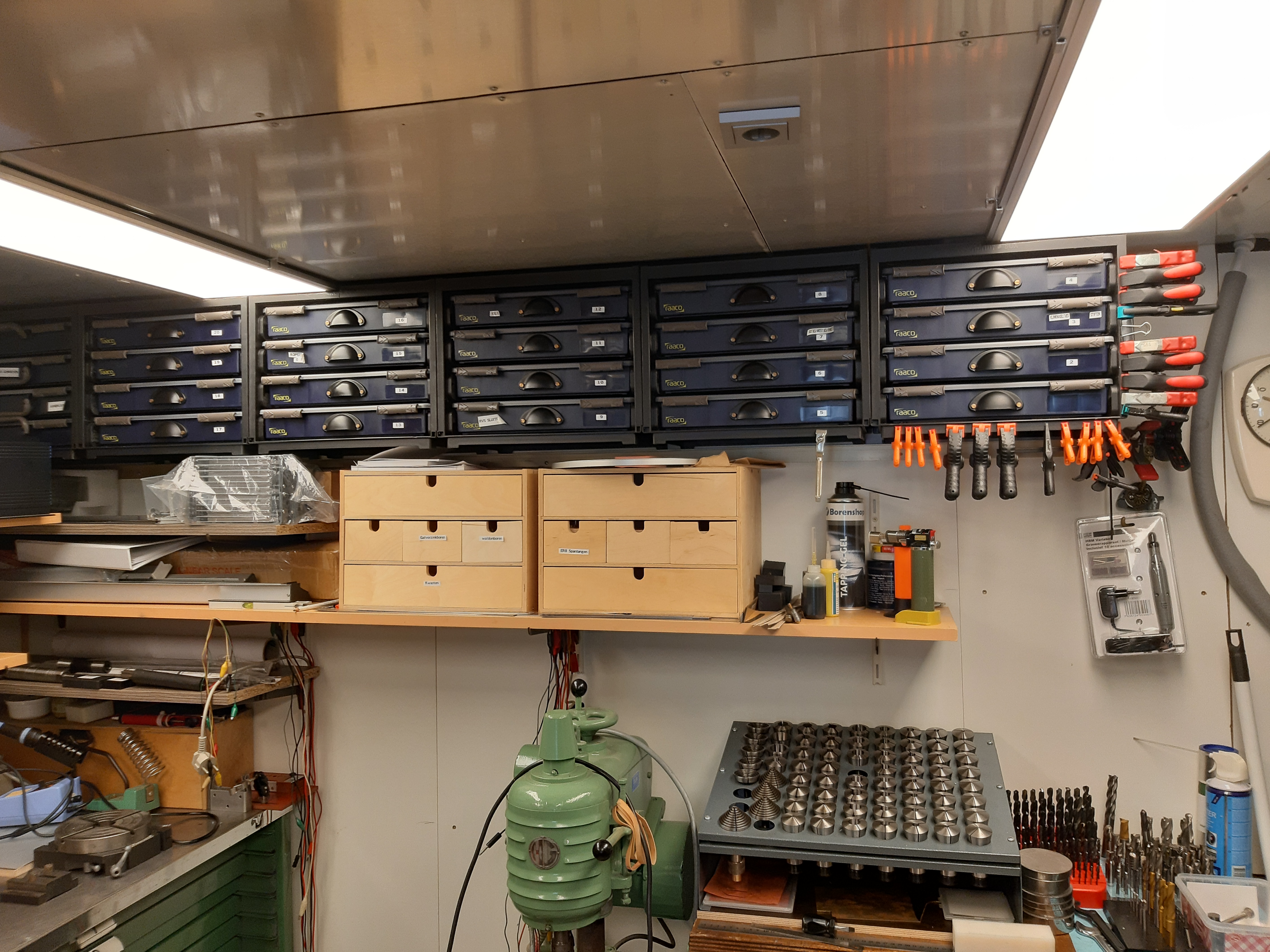
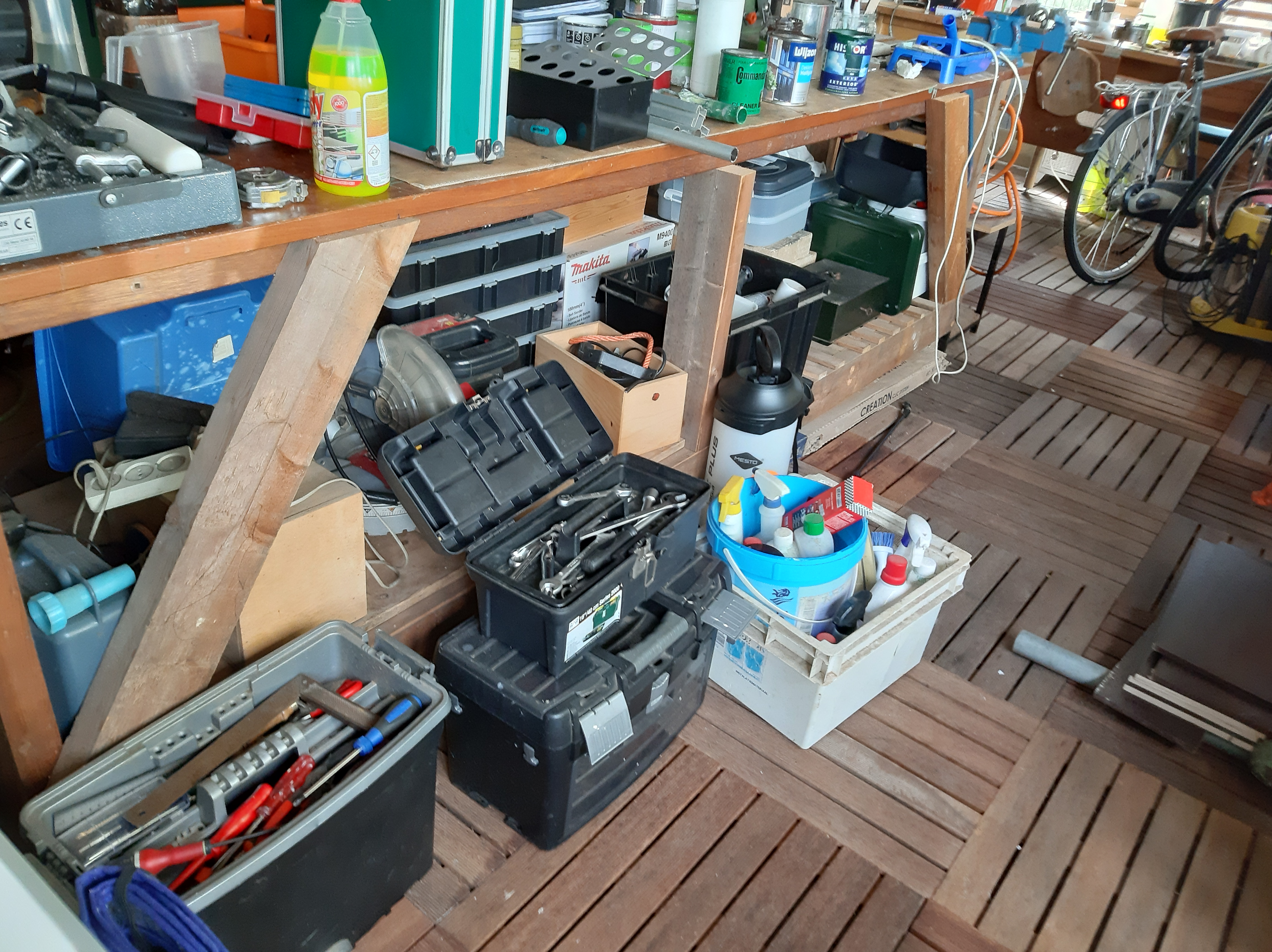
A European Workshop
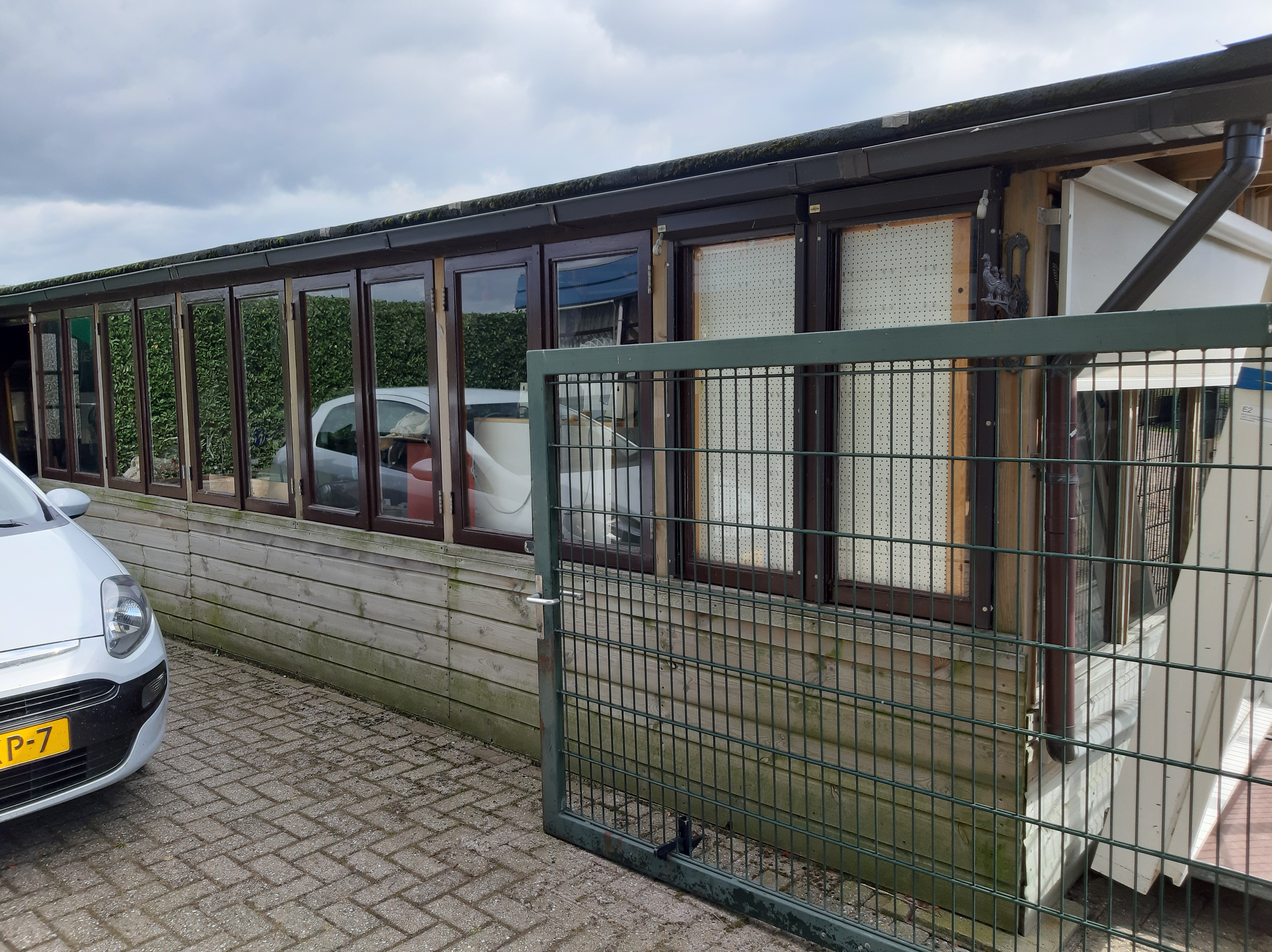
Most of the workshop pictures so far have come from Australia, and one from UK. This one is from Holland, sorry Huib, the Netherlands.
Interesting differences. Huib built his own workshop, and he has some nice gear. All of these photos came upside-down. Funny how they consider Oz to be “down-under”. Obviously their reference points are wrong. THEY are the upside-down ones. I mean, we are walking upright, right? They must be upside-down!
Hello John,
Here finally my contribution to your workshop series, as always I might want to show and share too much with others, that’s why I want you to show what you can support and is in line with the possibilities you have on your blog.
See if you can make one blog part of it or cut it into pieces. That’s up to you. I transfer the pictures with WE TRANSFER to you, as it is right you got a mail with the link to download the pictures.
It looks like the pictures that it is all clean and tidy maybe but appearances are deceptive, most of the time it’s not so tidy for me either, for the pictures I cleaned it up.
I have tried to be as complete as possible but if there are any questions please let me know.
I built the barn myself, so as the floor plan was drawn. First I built room 1 which is completely isolated and where I can work during the winter, there are also the most expensive machines.
Later on I built room 2, to store also the wood for the stove. Finally, 5 years ago I built room 3, the largest room where also other things are stored as only hobby stuff, also our bikes and everthing els.
Room 1 is the room where I stay most in, coarse work I do room 2, such as sawing, sanding and coarse drilling. In room 3 I mainly do business that need some space, the large, homemade workbench is a good tool for that. And as you can see, I can’t throw anything away and I keep everything I think of that can be useful in the next hundred years.
The photos contain references to the machine and the space where they are located.
I hope you like the total information.
Kindest regards
Huib

The thing about Holland, is that they HAVE to make the world’s best pumps. Otherwise they are under water. Much of the country is below sea level.
Now, that is nice!
Ahhh!
Ahhhhhh!

Nice! But I will stick with CNC.
Huib also sent a video of his steam plant. Unfortunately I do not have the space to post it, but if Huib can remember the YouTube address I will include that later.
Storage is always a problem no?
So, thank you Huib, for sharing your workplace with us. It is very interesting to see how other model engineers work, and their equipment. I have posted only a fraction of Huib’s photos, due to space limitations. I hope that the chosen shots are of interest to my readers.
ps. Huib, I found the YouTube video…Very nice work!
May 20, 2019
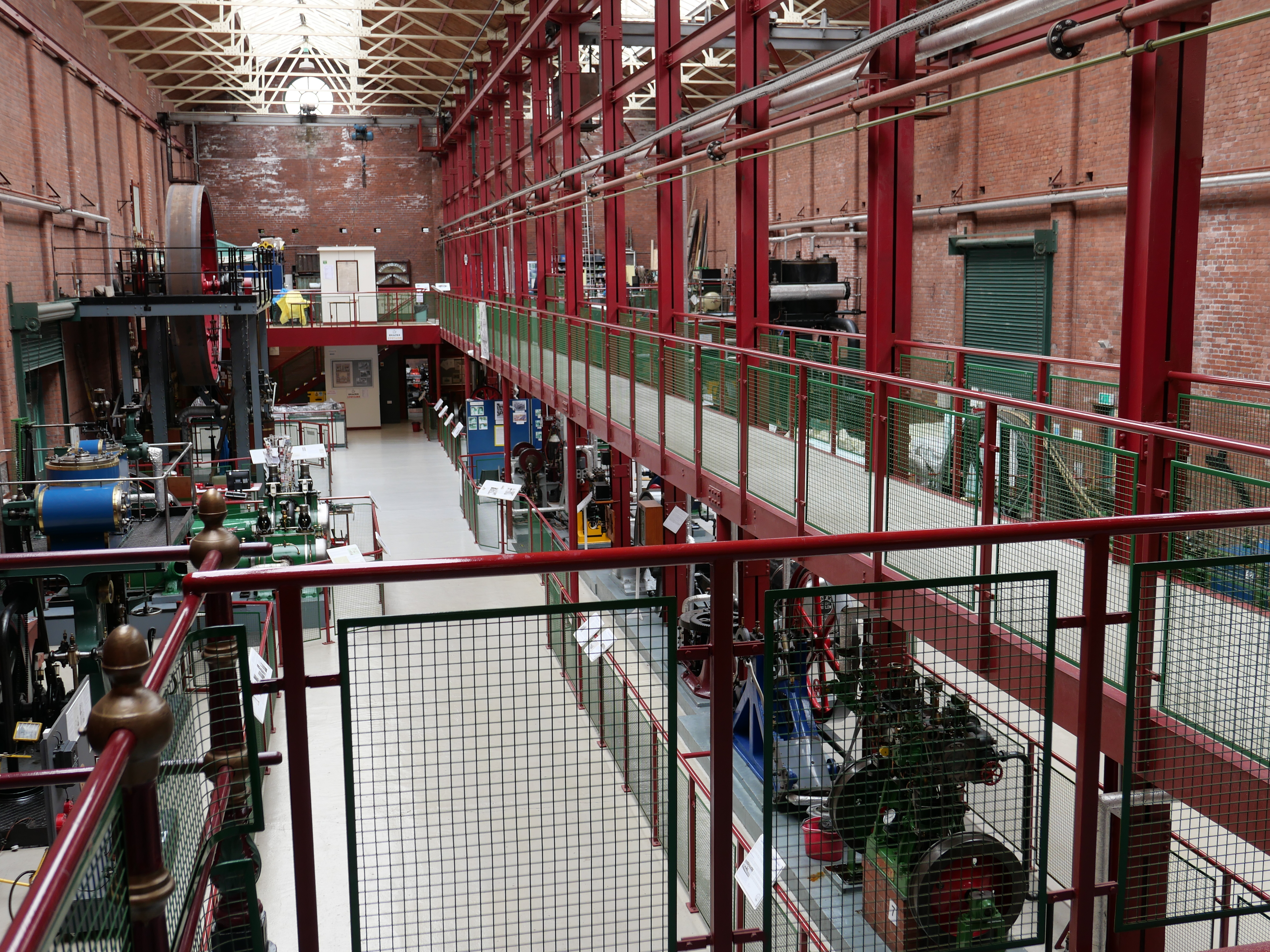
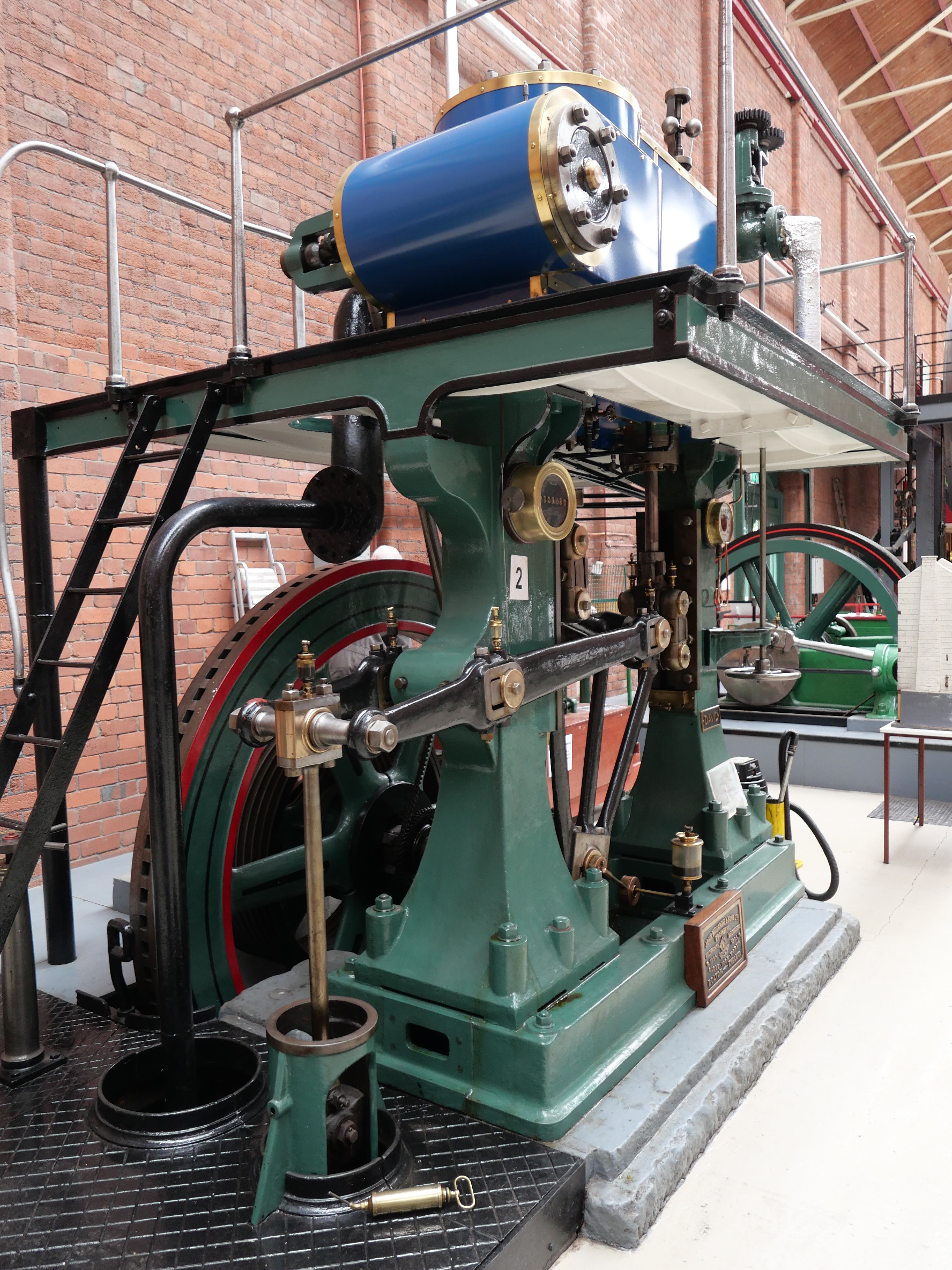
Bolton Steam Museum
I was a bit unsure about visiting this one. A smaller museum, and I knew from the web site that it was not a steaming day. But it was only a half hour drive, so off I went. I arrived at the address, and there was a supermarket, but in a corner of the supermarket block there was a tall, old, sizeable red brick building with no windows. And a sign… “Bolton Steam Museum”.
In I wandered, and a gentleman in overalls approached. This was a volunteer working day. But Ian (apologies if I got the name wrong), stopped his task and spent over an hour showing me around, explaining the finer points of his babies, starting some of them on electric motors to demonstrate the movements, then invited me to a cuppa with his mates, where there was further discussion, mainly about rope drives and stone engine bases.
No parking or entry fee on a non steaming day, (but a donation was appreciated).
The machines were not the monsters of Kewbridge or Kempton pumping stations. They were mostly from the industrial age of the midlands 1840-1930, powering textile mills, sawmills, and factories. Some were quite big. All were beautifully restored and presented, and for once, the descriptive labels had lots of information about the physical characteristics and histories of the engines. A nice aspect was the elevated walkway down the centre of the room, allowing a good view above the engines.
Some photos follow. Not as many as the museum deserves, because I am nudging my Wordpress limits.
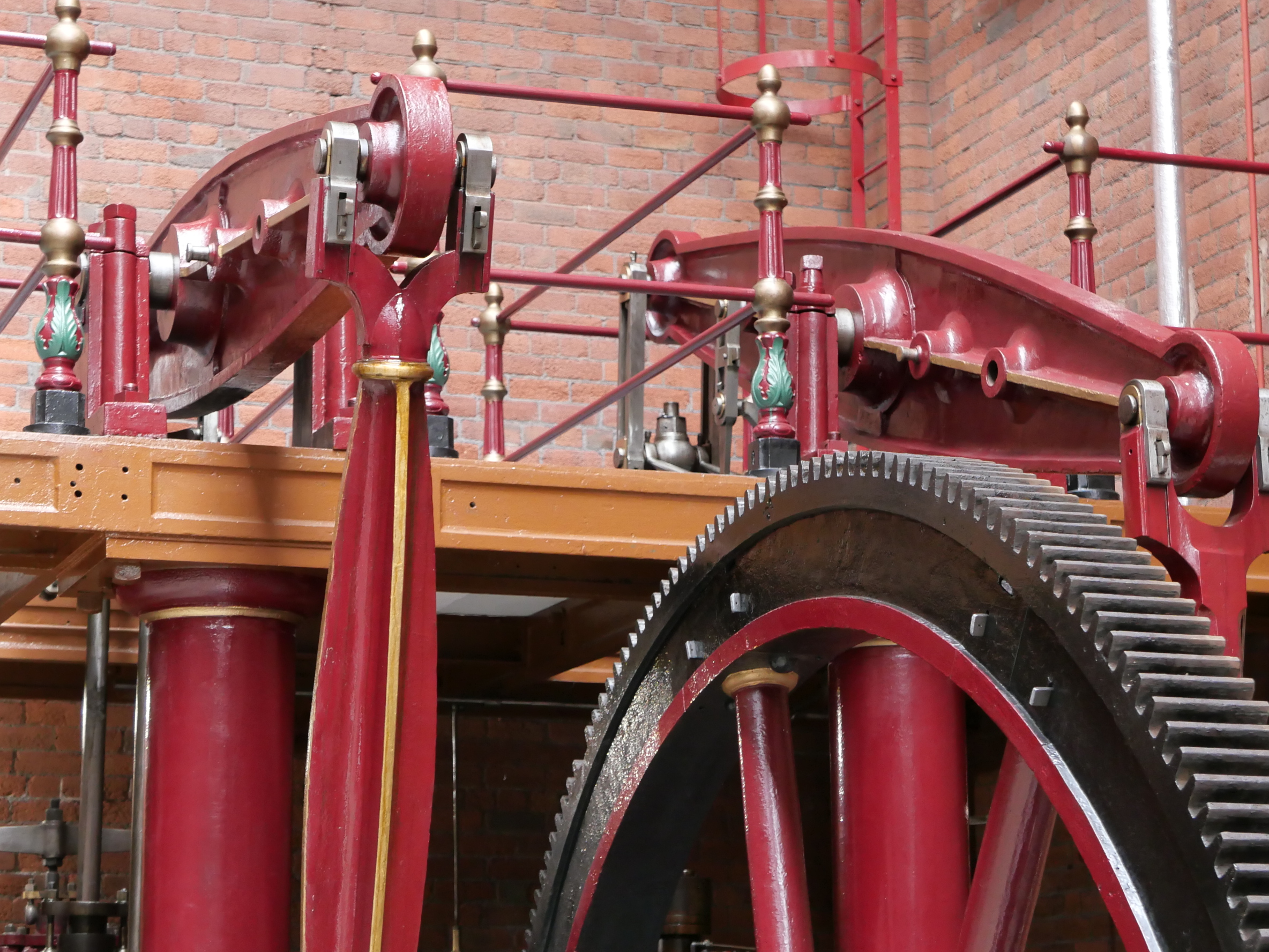
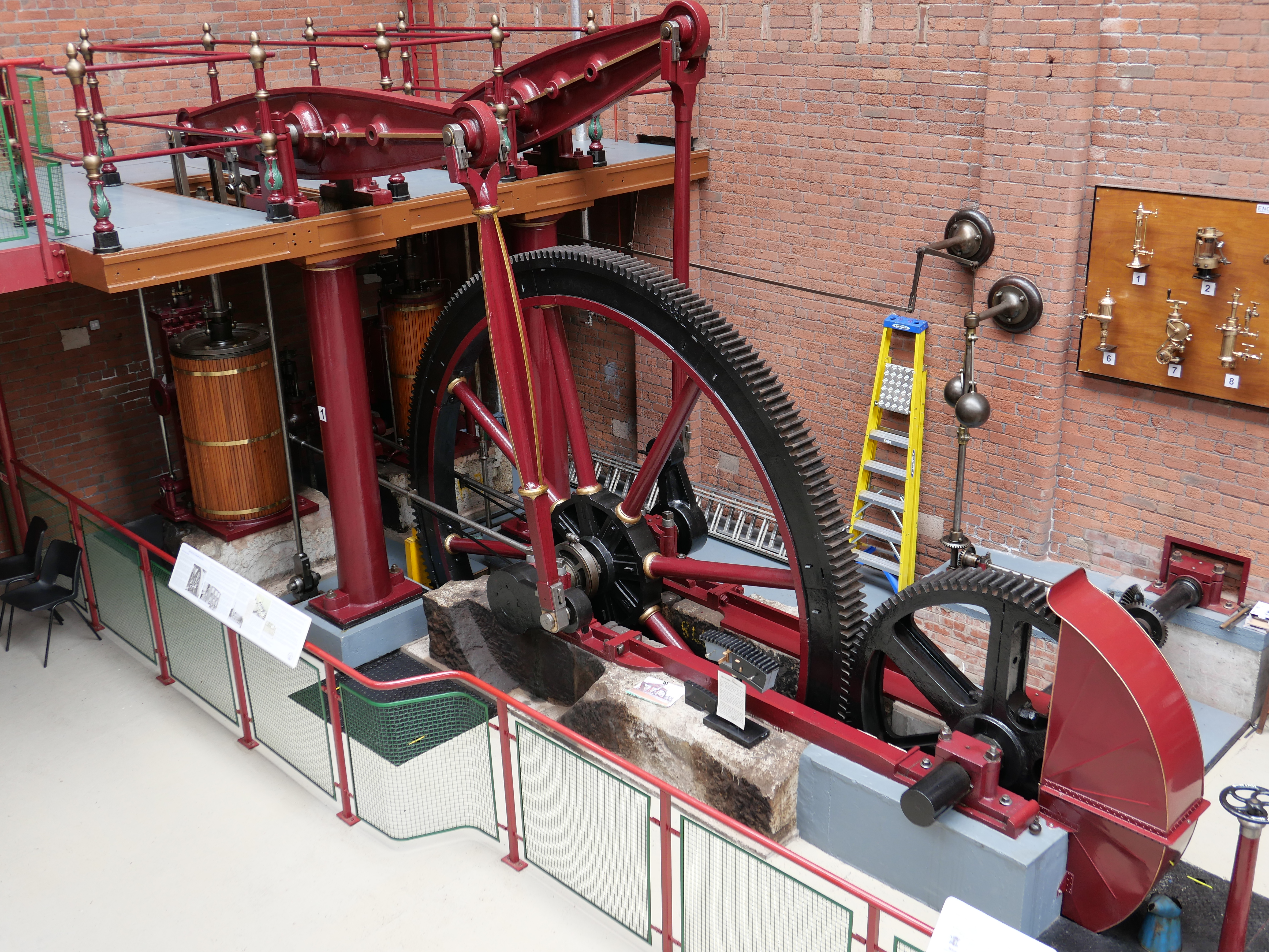
The twin beam engine of 1840 is the oldest engine in the museum. It started life as a twin, but when higher pressure steam became available it was converted to a compound twin. Note the non identical con rods. That happened during the conversion to compound. Partly seen is an excellent collection of engine lubricators.
This is a “non dead centre” engine. It has 2 con rods, one for each piston, but only one crank. Watch the video below and see if you can figure it out. It ran 100 looms in a textile mill.
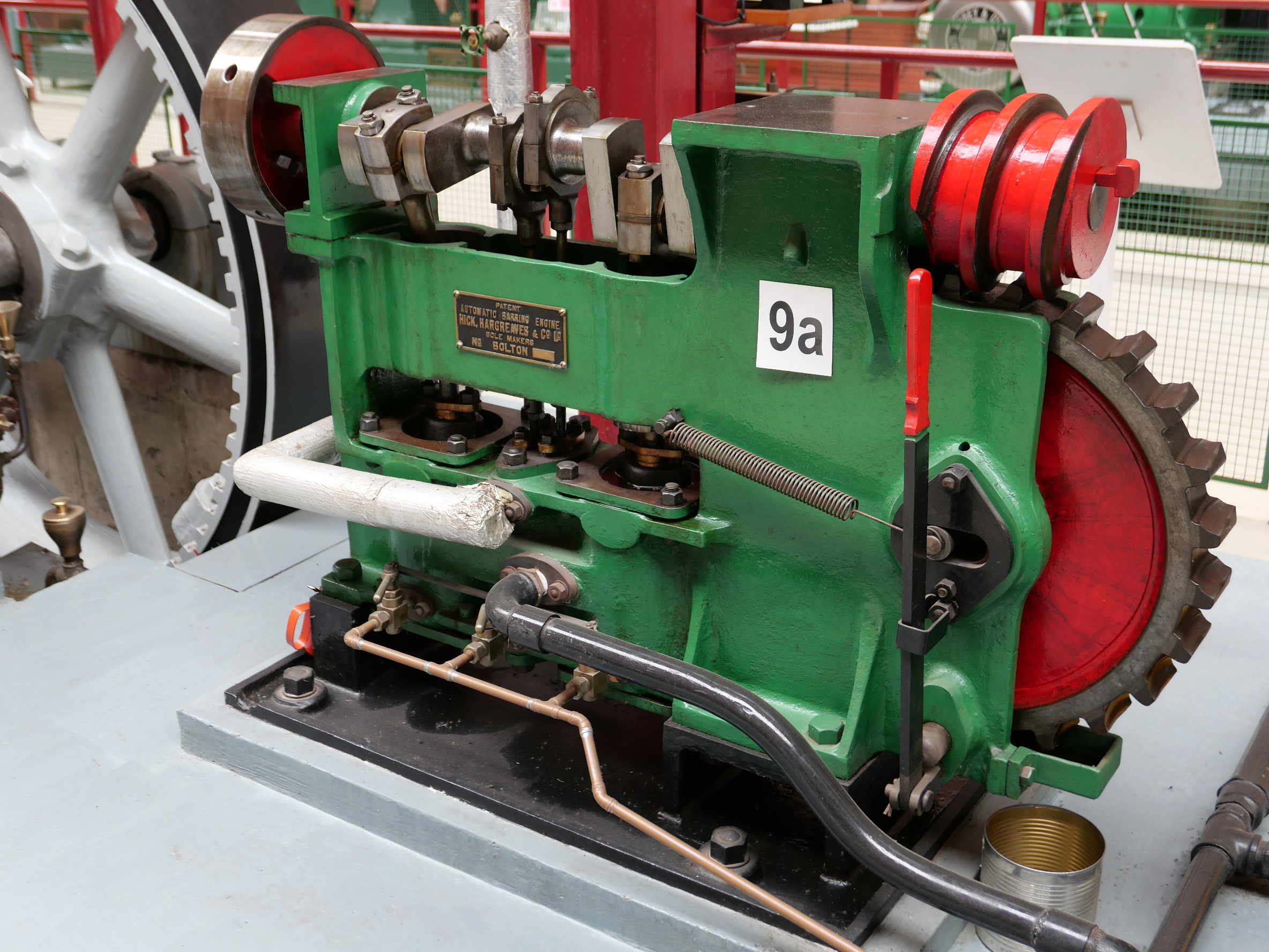
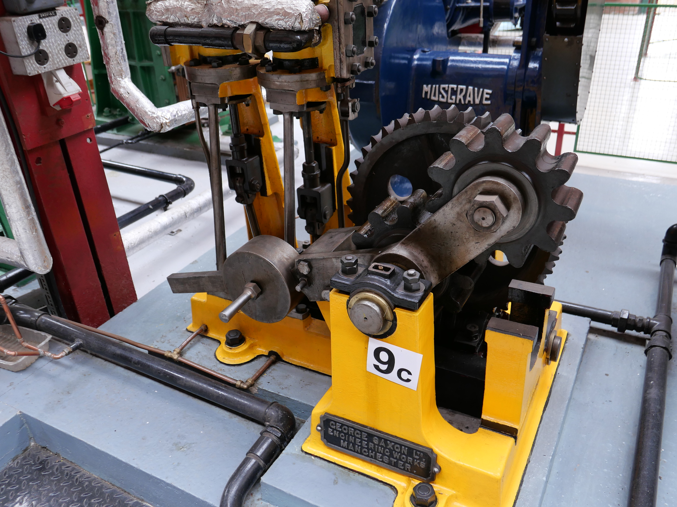
Two of the barring engines. These were small steam engines which were used to rotate the flywheel of a much bigger engine, to its correct starting position.
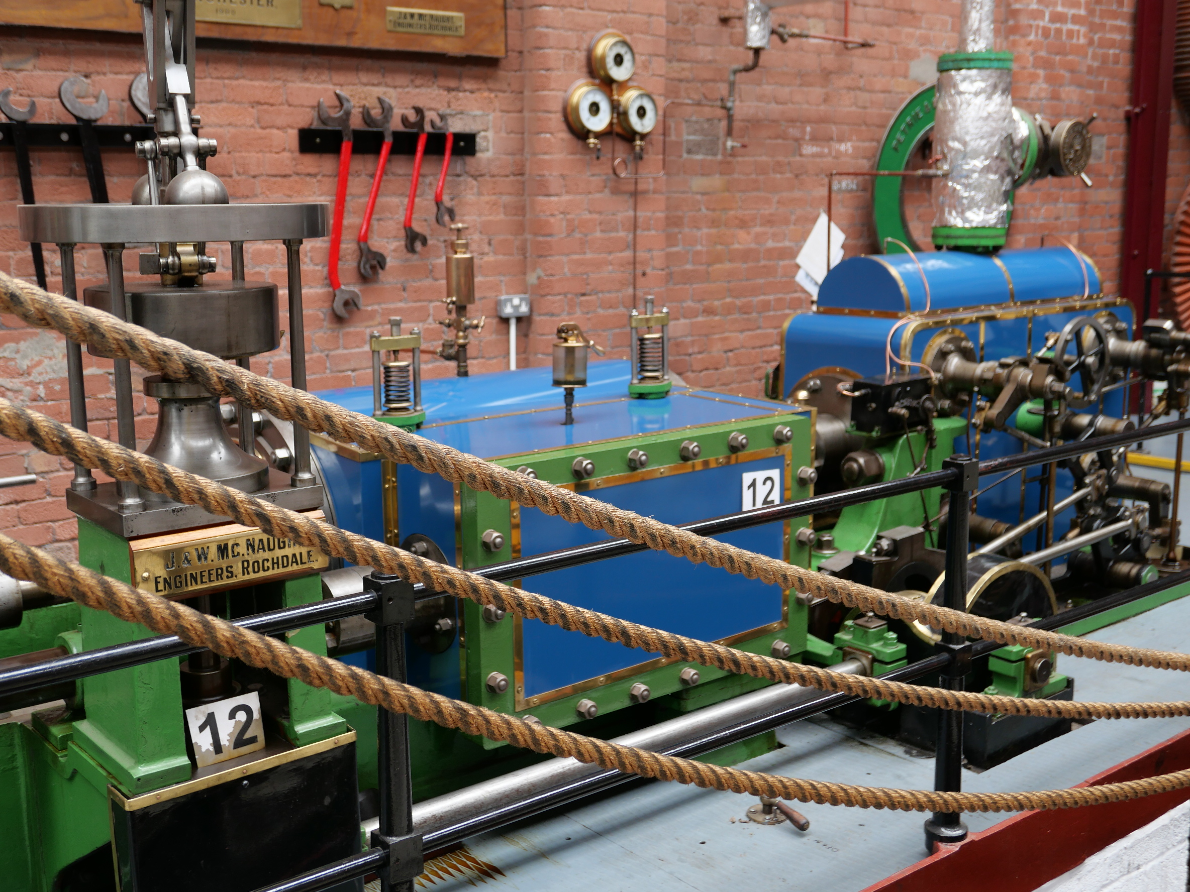
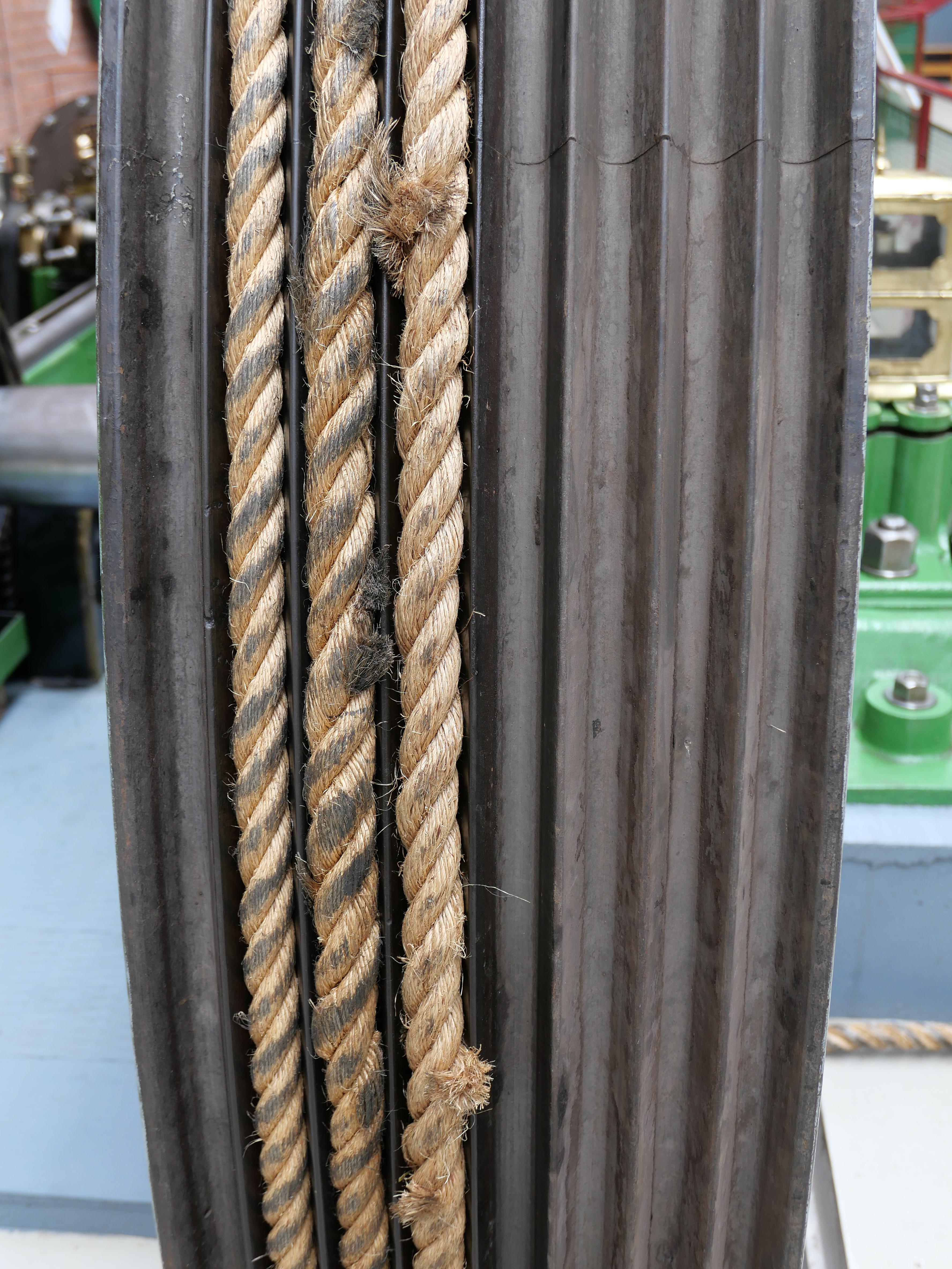
For the first time ever, I saw rope drives in action. Rope made of cotton was preferred, but these days sisal is usually used. Each rope could transmit 54hp if made of cotton, 30hp if sisal. They worked in V shaped grooves, and hung rather loosely between the pulleys, the weight of the rope wedging the rope into the groove. The splices, joining the rope into an endless loop were made by specialists, on the engine, and unlike marine splices, barely increased the diameter of the rope. The splices which I saw extended over about 2 meters of the rope.
This museum is another gem. I have described only a few of the 24 major items on display. There are many more, including engine lubricators, gauges, and valves. It was well worth the stay in Manchester, and more than made up for my disappointment at the Museum of Science and Industry. Try to see it on a steaming day. The dates are published on the website http://www.nmes.org
Also, the 36 page “Souvenir Museum Guide” is the best guide of its type I have encountered and contains detailed descriptions and colour photographs of the major exhibits. It is a steal for £2. The History of the Bolton Steam Museum is 64 pages, crammed with photos, and after a quick browse I am looking forward to reading it. Also IMO, a steal at £3.
Sincere thanks to the volunteers who shared their enthusiasm for steam engines with me today. I do hope to return one day to see the engines running on steam.
March 12, 2019
Next Project
The Trevithick dredger engine model is almost finished. Currently applying some paint. And getting it ready for the final boiler inspection. I am guessing about 2 weeks.
I have chosen a spot in the house where it will sit, and will post a photo in due course.
A few people have been asking if I have decided what to make next. In terms of a major build, the answer is no, I have not decided. I have considered a few possibilities. Those possibilities include a model of Stephenson’s “Rocket”, Trevithick’s “Catch Me Who Can” or “Pen-y-darren engine”, a Shand-Mason fire engine, or even another cannon.
What I will do, is to complete several unfinished projects, and if a major project becomes obvious, imperative, then anything is possible.
The unfinished projects include…
- An Arduino controlled rotary table. The mechanicals are made. Just need to dive into the electronics.
- The Southworth steam powered boiler feed pump for the vertical boiler.
- The CNC controlled tool post milling attachment for the Boxford CNC lathe.
- Paint the Bolton beam engine. Lag the cylinder. Install a cylinder oiler.
- Finish the triple expansion model marine engine. The lagging, the piston rings, the gaskets, the oiler and oil pipework, and painting.
Looking at that list, I really do not need to start another major project.
And sometimes it is nice to sit back, and enjoy the glow and satisfaction of previous projects. It does sound rather self satisfied, no? So here is a selection of videos, mostly first runs of newly completed projects. Most are YouTube links, but one or two will run directly.
This was the first model steam engine which I made about 5-6 years ago. It is a Bolton 7 single cylinder mill engine, and this was the first occasion I had run it on steam. It was a very exciting moment, seeing it actually running on steam.
Next came the Bolton 12 Beam Engine. Still a crowd favourite. The beard was ordered off by SWMBO not long after this.
Then a couple of Stirling engines. How they work is still a mystery to me.
Then the problematic, difficult triple expansion engine, which took 3 years and several extended breaks to get to the working stage. Still not finished completely. Stuart Tankard’s boiler. Since then I made a vertical boiler.
And somewhere in there I made this little reversing engine for the club competition. Alas, it failed in action.
And 3 cannons came out of left field. They started as a CNC project, but then took on a consuming interest of their own. About this time I saw the necessity of learning how to put together a video. Still learning.
The 6″ vertical boiler.
And finally the Trevithick dredger engine. The historical aspects of this engine, the genius of Trevithick, the fact that the engine works…. has been marvellous. The engine is looking quite different with some paint applied. And the propane burner is significantly better than appears in this video.
So, if you are still with me after all of those videos, congratulations on your stamina. It is therapeutic to take stock sometimes, and to wonder about where making all of these engines is going. It was not to any plan. Still no plan. Just enjoying the moments, the days.
March 5, 2019
Trevithick Blower
I am sure that my readers will have gathered by now that I am not an expert. At least in matters of metalworking, model engineering etc. I am, or was, an expert in my profession, some years ago. But this blog is about how a non expert copes with problems in model engineering. It aims to be entertaining, occasionally helpful, and a diary of my workshop doings.
When Trevithick designed his revolutionary engine, (“revolutionary” in all senses), he arranged for the exhausted steam to be funnelled into the chimney, after pre-heating the boiler feed water.
It was a matter of convenience apparently. Rather than ejecting the spent steam directly into the air, it would go up the chimney, away from the operator.
But almost immediately it was noticed that the fire in the firebox was more vigorous, hotter, more efficient Thus was born, the steam engine blower.
So I made the junction between the exhaust and the chimney as per the plans, at an angle of 90 degrees.
But, I noted that on the exhaust stroke, the fire in the firebox spluttered, and occasionally went out altogether.
In more modern steam engines, the exhausted steam is inserted into the chimney, but parallel with the chimney, not at a right angle.
So, I thought, do I stay with the Trevithick design, or the more logical more modern design. I was having problems with my fire, so the decision was easy. I would pretend that Trevithick would adopted this design. Maybe he did.
But that meant breaking the silver soldered join, inserting a new angled copper tube, and rejoining it all.
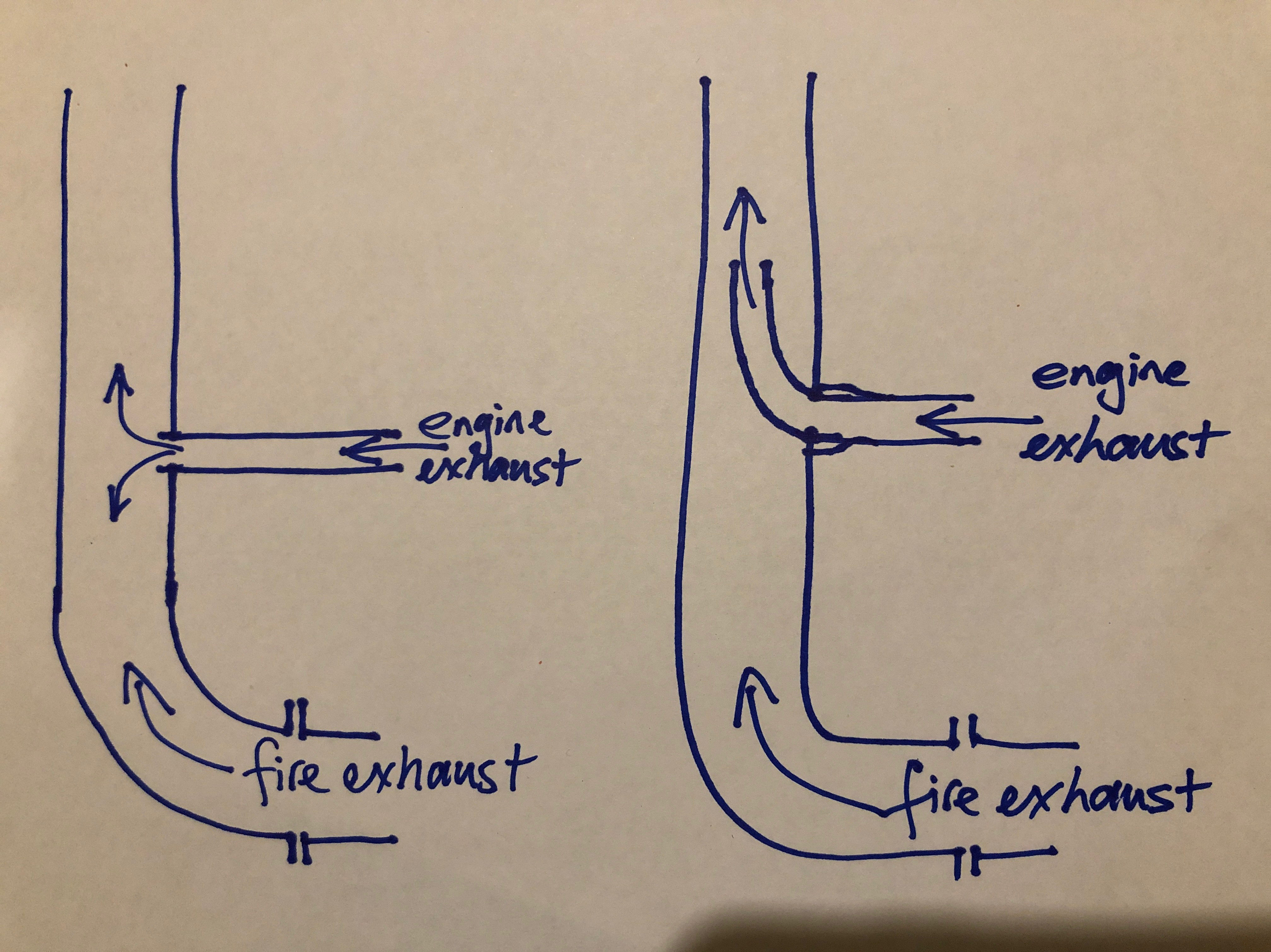
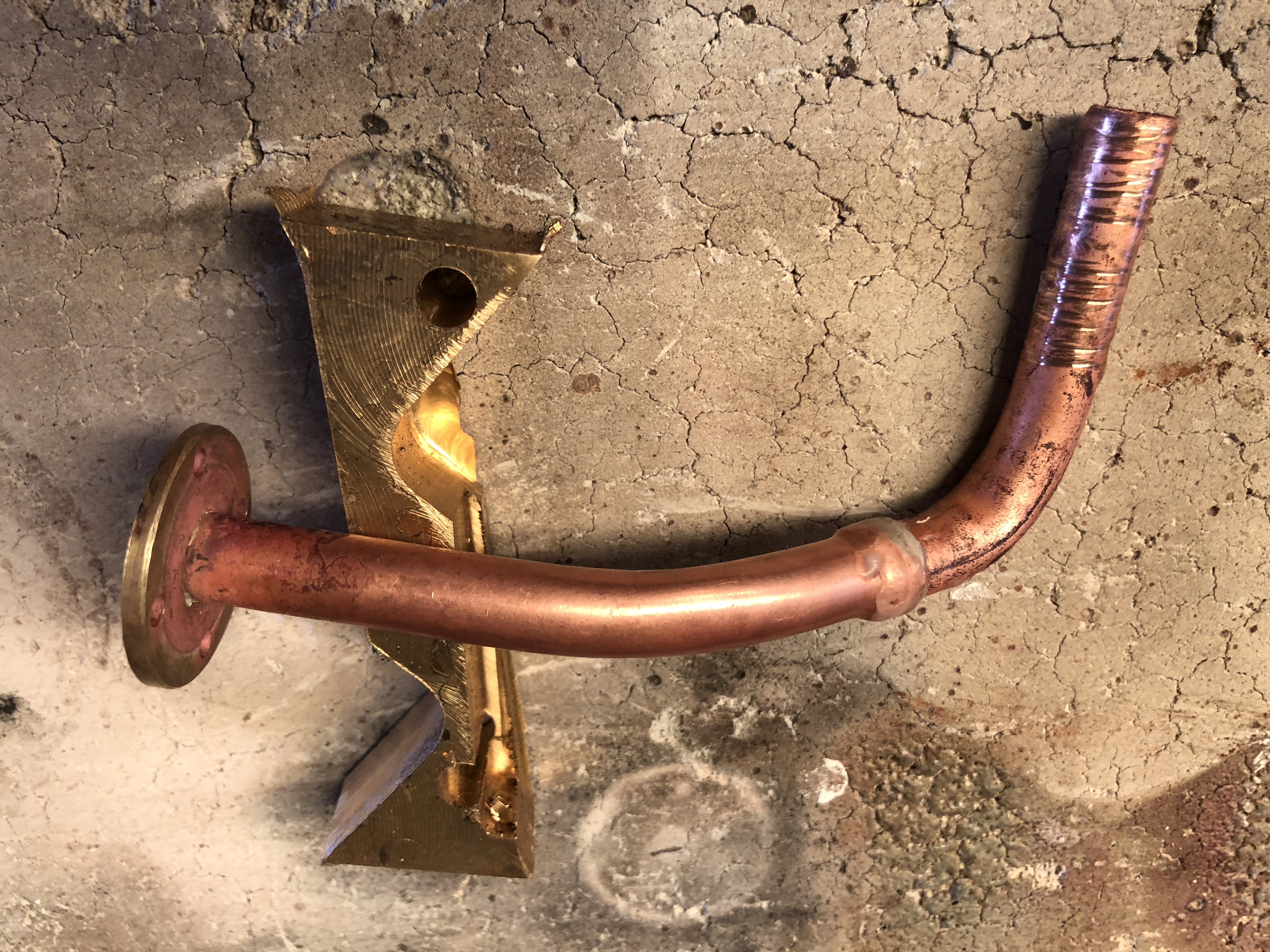
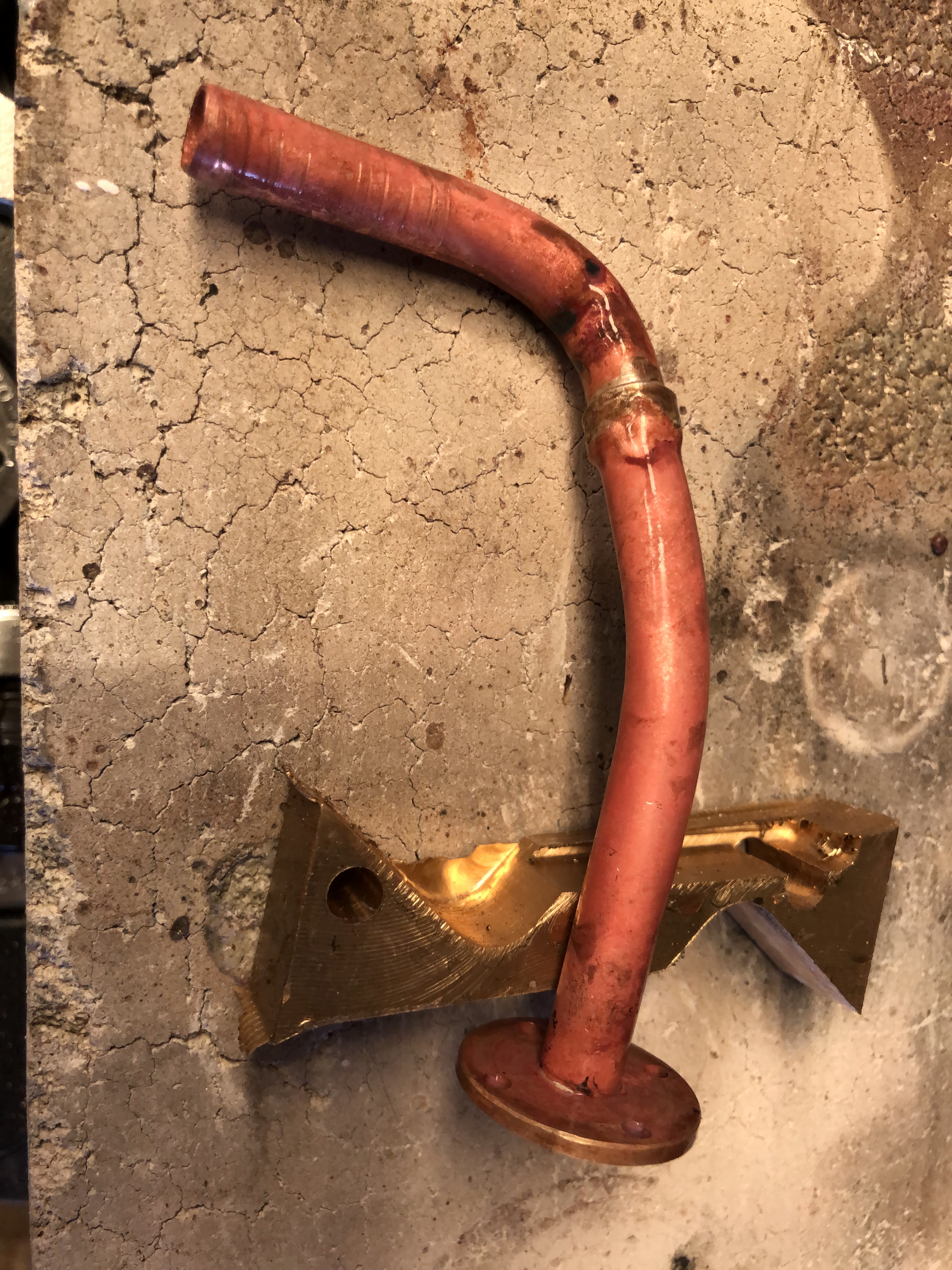
As Trevithick designed it on the left and on the right as I remade it today
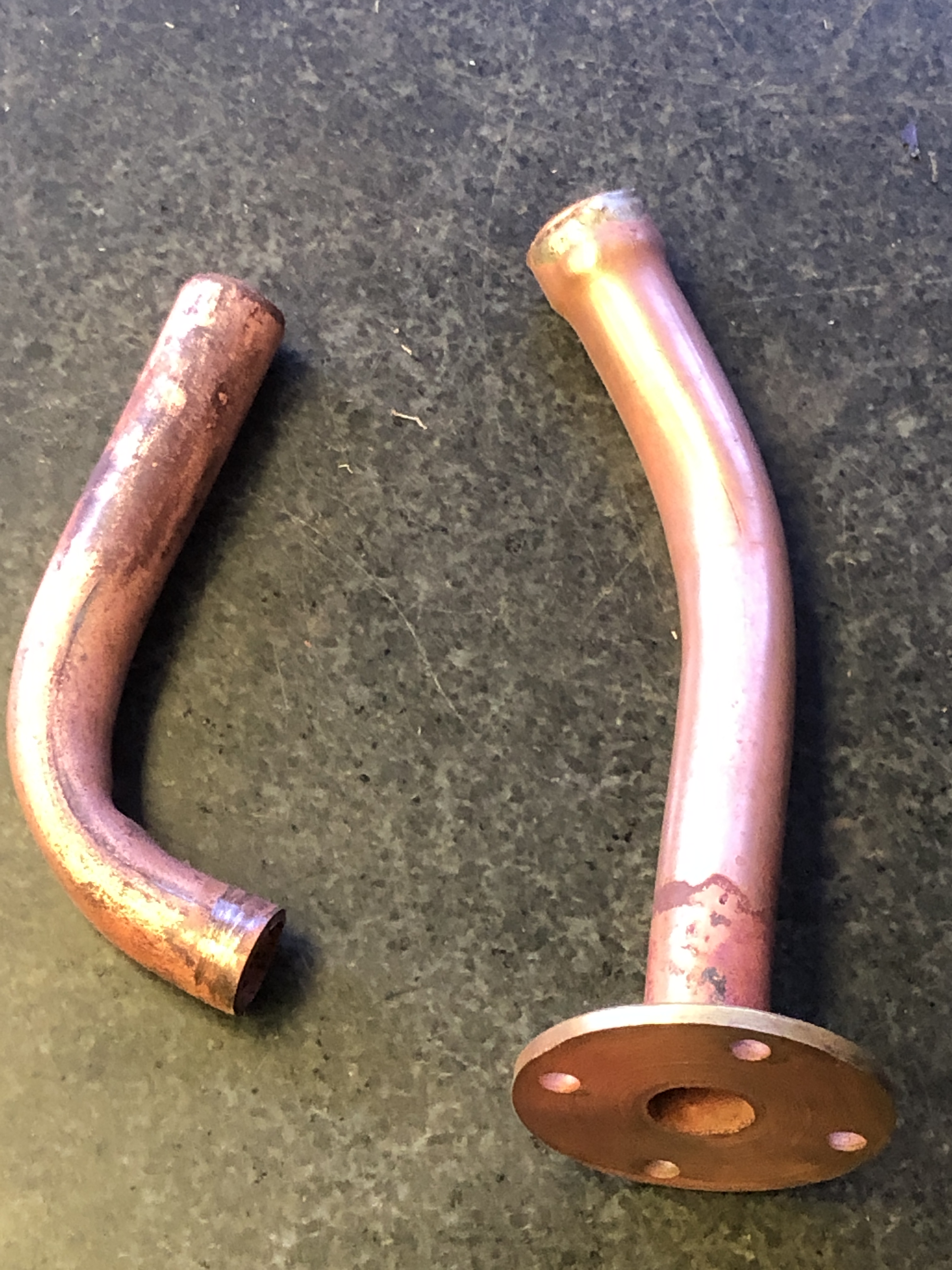
Right is the exhaust piece between the preheater and the chimney. Left is the new blower tube, which must be joined end to end, and then poked up the chimney.
This was going to be tricky. And end to end join of 2 pieces of 9.5mm copper tube, and the join being right where the tube enters the chimney. But then I remembered a tool which had sat unused for several years…
Error
This video doesn’t exist
OK, This is probably very old hat to most of you. But it was exciting to me. First I had to assemble the tool. Sorry I missed the camera.
Error
This video doesn’t exist
Error
This video doesn’t exist
I decided to solder the pipe join first. Rested the end with the flange on a lump of scrap brass, to act as a heat sink, and protect the flange join.
That worked well.
Then I soldered the assembly into the chimney, after bolting all of the parts into their positions. Sorry. Forgot to take a photo. But it all worked well. I like the tube expander, but it needs some extra fittings so it works on smaller tubes.
March 4, 2019
Trevithick Dredger Engine. Almost There.
Firstly some pictures.
So, I have reassembled the engine and the burner and the base.
Did you notice the base?
No? Excellent. That is the idea. A nondescript matt black base which is barely noticed.
Yes? OK, well it must be OK.
Then a trial of the burner inside the firebox, using the changes which have evolved over the past few days.
During the video I am constantly changing the propane flow, and there is a clear “sweet spot” point where it looks really good, and feels very hot. I have not yet tried to steam with it.
March 2, 2019
Beware of Greeks Bearing Gifts
Well, this one is OK because it came from a Hollander.
One of my blog readers, Huib, decided that I would be the recipient of some of his workshop items which he says were surplus. This was as a thank you for johnsmachines.com.
So, a parcel arrived yesterday, and after a quick look inside, I decided to make a video of opening the items, and showing you. It was great fun for me, and I hope that it will be entertaining for you. It is the biggest file which I have uploaded, so give it a few minutes to open.
Oh, any other readers who would like to send me surplus tools or other interesting bits and pieces…. please feel free. If Haas, or Hardinge would like a review on one of their machines please send it and I would be happy to do a review.
February 24, 2019
Model Trevithick Dredger Engine on Steam. Fail. Well, maybe a bare pass.
Well, I was really not expecting this.
After all, the engine was running well on compressed air at 30psi, and the burner appeared to have a good flame.
And Stuart was coming to be involved with the big event. So nothing could go wrong!
I set up the iphone on a tripod. Checked the light. Oiled the bearings and slides. Filled the boiler. It takes 2 litres of water. And hooked up the propane. when Stuart arrived I lit up the burner, and sat back to see how long it would take to raise steam.
Some steam leaks were expected, on this first steam run. Leaks don’t show on compressed air, unless they are severe. As the water heated up, some leaks appeared. The water feed clack valve and the sight glass were bad. The clack valve just needed some goo. Later I disassembled the sight glass, and cleaned the valve, with some improvement, but more work needed. Or a new sight glass valve. A couple of other trivial leaks were easily fixed.
So we watched the clock, and checked the temperatures. Ot took 20 minutes to start raising steam. That is a bit slow. Eventually it reached 20psi, but the pressure refused to go any higher, despite fiddling with the gas and air controls.
At 20psi, I opened the throttle and gave the flywheel a swing. You can see the result.
After that, we let it cool down and fixed the clack valve leak. The sight glass valve leak was looked at later, but could not be fixed simply.
The burner flame. A bit feeble. A bit yellow. And occasionally blown out by the cylinder exhaust gas puffing into the chimney. Stuart says that I need to angle the cylinder exhaust gas upwards in the chimney. Apparently Trevithick did not do that on the full size models, but perhaps he should have.
The burner was definitely not up to the job, so in this last video, it got some assistance.
It does go! Just needs a few tweaks. Lovely sound.
February 18, 2019
Sight Glass on the Trevithick Boiler
Not real happy about this one, but it is necessary if I am to run the dredger engine in public, at club meetings etc.
The original dredger engine had 3 taps to check on the boiler water levels, like this.

An earlier stage of construction, using taps to reveal the boiler water level.
Unfortunately that setup is unacceptable for boiler certification, so I have installed a sight glass using the same penetrations.

The red colour does not help. But when I run the engine on steam, this is what will be seen. Functional, but nothing like the original. If I use compressed air, or steam from an outside boiler (i.e. my burner not being used), I can reinstall the taps.
The sight glass is a bit short, but it should comply with the regulations.
I have spent another half day experimenting with different spring configurations, so that the safety valve releases at 40-50psi. Eventually I decreased the coil pitch of the spring, and the valve now releases at 45-50psi. That will do.
February 16, 2019
A Tour of the Model Dredger Engine
Now that I have a tripod for my video camera (an iPhone), I have become a bit more enthusiastic about making videos. Terrible standard of video compared with Joe Pieszczynski, and This Old Tony, and Stefan Gotteswinter, but maybe better than just text and photos. I will be interested in your responses.
The Dredger Engine is still not quite fully made, but while I had the video set up for the spring making exercise yesterday, I added the following. It is totally unscripted, and unedited, so there are errors. “pressure valve” instead of “pressure gauge” for example. Have fun counting the errors. The final 30 seconds is me having difficulty turning off the camera!
Error
This video doesn’t exist
December 7, 2018
Read this response to Antarctic Weird
I received this email today. I am posting it with Jennifer Edwards’ permission. Just reading it made the hairs on my neck stand up!
BTW, I will continue posting until my current subscription runs out in a couple of months.
John,
sorry to see you go. I was enjoying your wit as well as great machining skills. I have the same issue with a web site I maintain for my partner. The bastids nickel and dime mw to death, send me renewal notices a year in advance, and try to sell me security crap with e-mails spouting fearful phrases that always seem to include the words “haters, Spammers, and internet thieves. I do not blame you for pulling out.
When reading about your Antarctic pictures it reminded me of an experience I had when I was about 18 years old. I have not told this to many people over the years simply because every time I do they look at me like I am crazy, however you seem to have an open mind so I will risk never hearing from you again….
The event occurred over forty six years ago. There were three of us present, and unfortunately I am the last surviving member of the group.
It was Late October 1972, the Friday evening before Halloween in Southern New Jersey. My future X, my little brother, and I were on our way from our home town of Cinnaminson to our family cabin on Bamber Lake, in the Southern New Jersey pine lands. I was driving. Our route took us on unimproved two lane back roads that normally only see farm traffic. The weather was a crisp and clear October evening with unlimited visibility.
About a mile east of Vincentown I rounded a bend and there it was in the north west corner of a small rectangular field of maybe three possibly four acres. The road ran the length of the field. The field was surrounded by large old oak trees along the West and the North. The road ran along the south boarder and then curved along the eastern boarder. The field was long and narrow.
As I rounded the bend a brilliant light caught my eye. There in the north West corner of the field was a large object hovering. It was shaped like a bell, about 40-50 feet high and maybe 70-80 feet in diameter. Only an oval dome at the top of the bell was above the tree line.
Upon later reflection we realised that the location of the object was less than three miles to McGuire AFB. It would have been a great vantage point to observe the airfield.
I noticed that there was a berm along the edge of the field which I drove up on to put my headlights on the object. We sat in awe for maybe 20 seconds at which time the three of us exited the car to get a better look. Please note, to this day whenever I think of that evening the hair stands up on my neck, it was that profound an experience.
The object was hovering, maybe ten feet off the ground. It was shaped like a bell with a convex bottom. It was a dirty whitish grayish in colour. The apex had a brilliant white light which radiated beautiful, quickly pulsing, beams of light in pure crystalline colours, vivid blue, violet, red, and green. The beams seemed to come from a brilliant blue white point just below the oval disk on the top of the “bell” to a row of the same colour of white lights evenly spaced along the rim, then from those white spots to another white light in the centre of the convex bottom of the craft.
Maybe ten years later I saw my first laser light demonstration, it was that type of pure crystalline single wavelength light that instantly reminded me of that object. In fact the hairs on the back of my neck and on my arms stood straight up.
As it hovered it made a sound akin to a very large saw mill blade swinging. I cannot find other words to describe that whirring sound other than a saw mill blade spinning.
The three of us were standing in front of the car, headlights on the object just gawking at the objet. This went on for maybe a minute possibly a minute and a half.
BTW I am a licensed pilot and also a highly experienced sea captain, I am a good observer, with an eye for size and distance. We were maybe 175-200 feet away from the object.
At that point I alone started walking towards it, my x and brother were too awestruck to move. When I got extremely close, less one hundred feet, probably more like seventy five feet away. The size of this thing sank in. It was the size of a small house! I started smelling that lightning storm ozone odour, began getting a strong metallic taste in my mouth, and felt tingly on my skin. This scared me so I made a slow retreat back to the car never taking my eyes off the object.
When I rejoined the other two we stood there for maybe two more minutes, just looking, listening to the whirring, not speaking beyond a few “wows” and “oh my gods”. Then it hit me, I had a Yashica 35mm camera loaded with asa 400 film and sporting a 200mm lens on the front seat.
I reached into the car, grabbed it and began fumbling trying to remember how to focus it when you could not see thru the view finder. It was one of those old 35mm cameras with all manual controls. I was unfamiliar with the camera and fumbled around. I never did get a shot, something I truly wish I had done, as anyone I related this story to since that day some forty six years ago has either thought I was crazy or simply humoured me.
Any way, as soon as I aimed the camera at the object it seemed to immediately react to the threatening move of pointing what may have been perceived as a weapon at it.
iI’s sound began to change. It got higher and higher and higher in pitch and volume until it was just a deafening hiss, like high pressure steam being vented thru a small aperture.
Some years later in San Diego I had another hair standing up moment when I went to work with a fixed hard disk manufacturer. We had tanks of liquid freon that were huge ultrasonic cleaners used to clean the 18” stainless steel disks before transferring them into the clean room for final assembly. The first time I turned one on and heard that hissss there went the hair standing up again. That was the frequency of the sound. This had to be around 1982.
Sorry to digress, any way the sounds frequency went up, the pulsing lights became gradually brighter and more brilliant until the entire craft was one very bright white fuzzy bell. The craft slowly rose to an altitude of maybe 150 feet. It slowly went on paralleling the road heading northeast about 100 feet to the west of the road.
We jumped in the car and followed. We were able to keep up with it for maybe a mile and a half while it slowly accelerated until it finally had a good lead of maybe several hundred yards. It’s altitude was increasing as was its rate of climb. Slowly at first, but obviously steadily accelerating in what settled in at about a 30 or 40 degree climb.. The road ended in a “Tee” intersection. So again we got out of the car and stood in the middle of the itersection watching as it continued its climbing. We were able to keep an eye on it due to the exceptionally clear sky and the fact that we were way out on the country, so light pollution was not a factor..
Finally after another five or more likely six minutes the thing was just another one of the stars in the sky. It grew fainter and fainter, until it was indiscernible from all the other stars.
At that point we got back in the car and continued on our way.
One interesting point is that from the point where that craft was to the runways of McGuire AFB is only a couple of miles. Back in 1972 the area of the jersey pines we were in had many Cold War installations,Nike missile installations, the Space Track “ golf Ball” and others. There had been a nuclear warhead on a missile that had caught fire and contaminated a very large area with plutonium, the active air base was there as well. Plenty to look at if you were interested In the military capability of a civilisation.
For the rest of our lives whenever either of the three of us met, right up to the ends of their lives, we always said ” hey remember the flying saucer”. I have only told this story to four or five others over the years. The blank stares or that look like you are some kind of nutter shut me down.
Any way there you have it. I wish you luck with your build, and YES please post a video when it is complete, and send me a link.
Thanks again,
Jenny
Jennifer Edwards
June 21, 2018
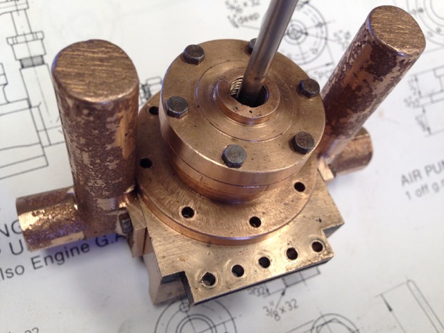
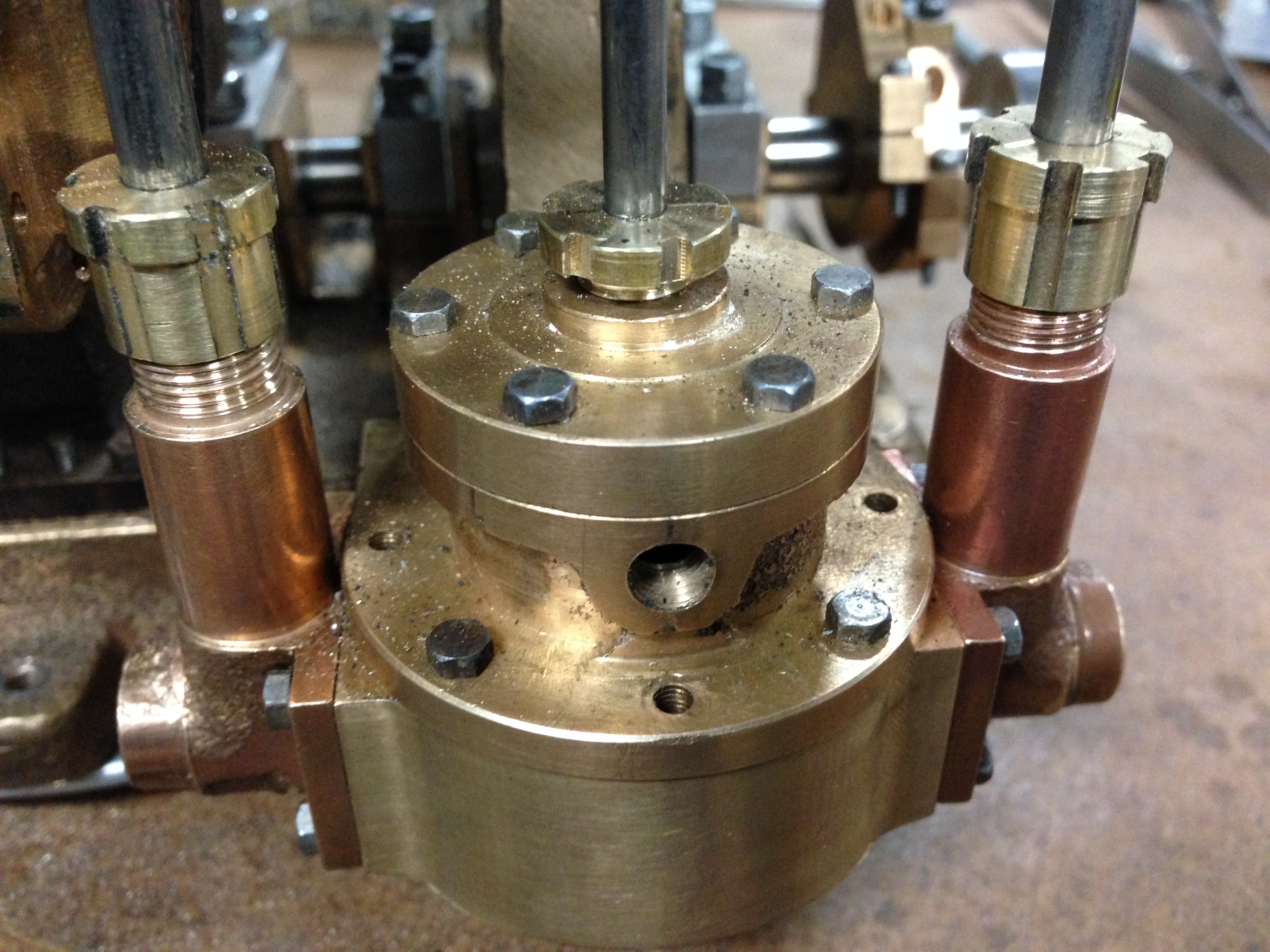
6″ Vertical Boiler- Penetrations
Another few hours in the workshop today.
Continuing preparing the parts for the boiler. Drilled and reamed 9 holes and the bronze bushes which will be brazed into them. The bushes provide the screw in points for water inlets and wet steam outlets, pressure gauge, water gauge.
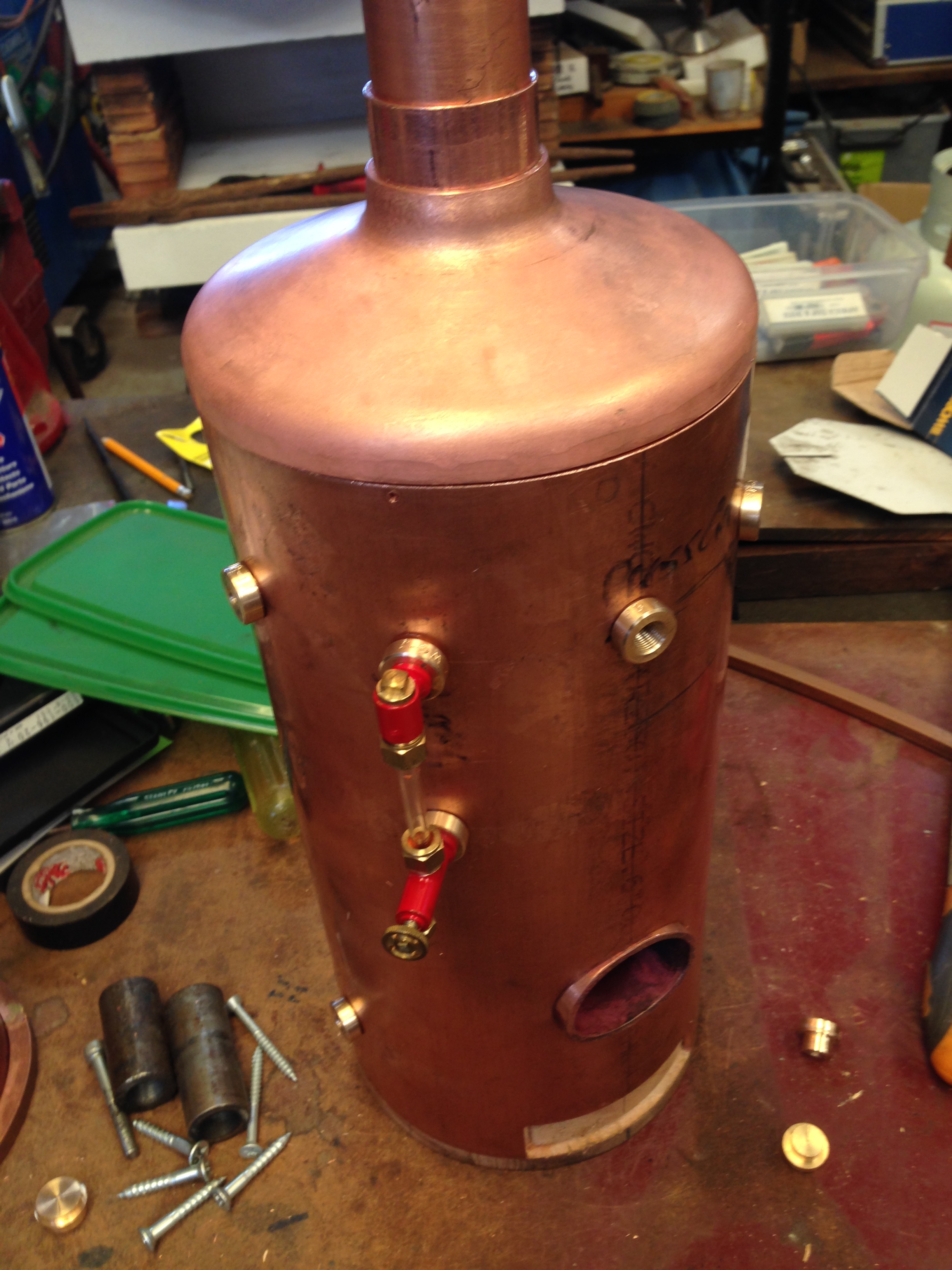
All of these components are just sitting in place, but giving an idea of size and form.
There will be no progress on the boiler for a week, due to forced absence from the workshop. Child minding the grandchildren. Hmmm… I wonder if a 2 year old could help in the workshop? Possibly not a good idea. Yet.
October 28, 2017
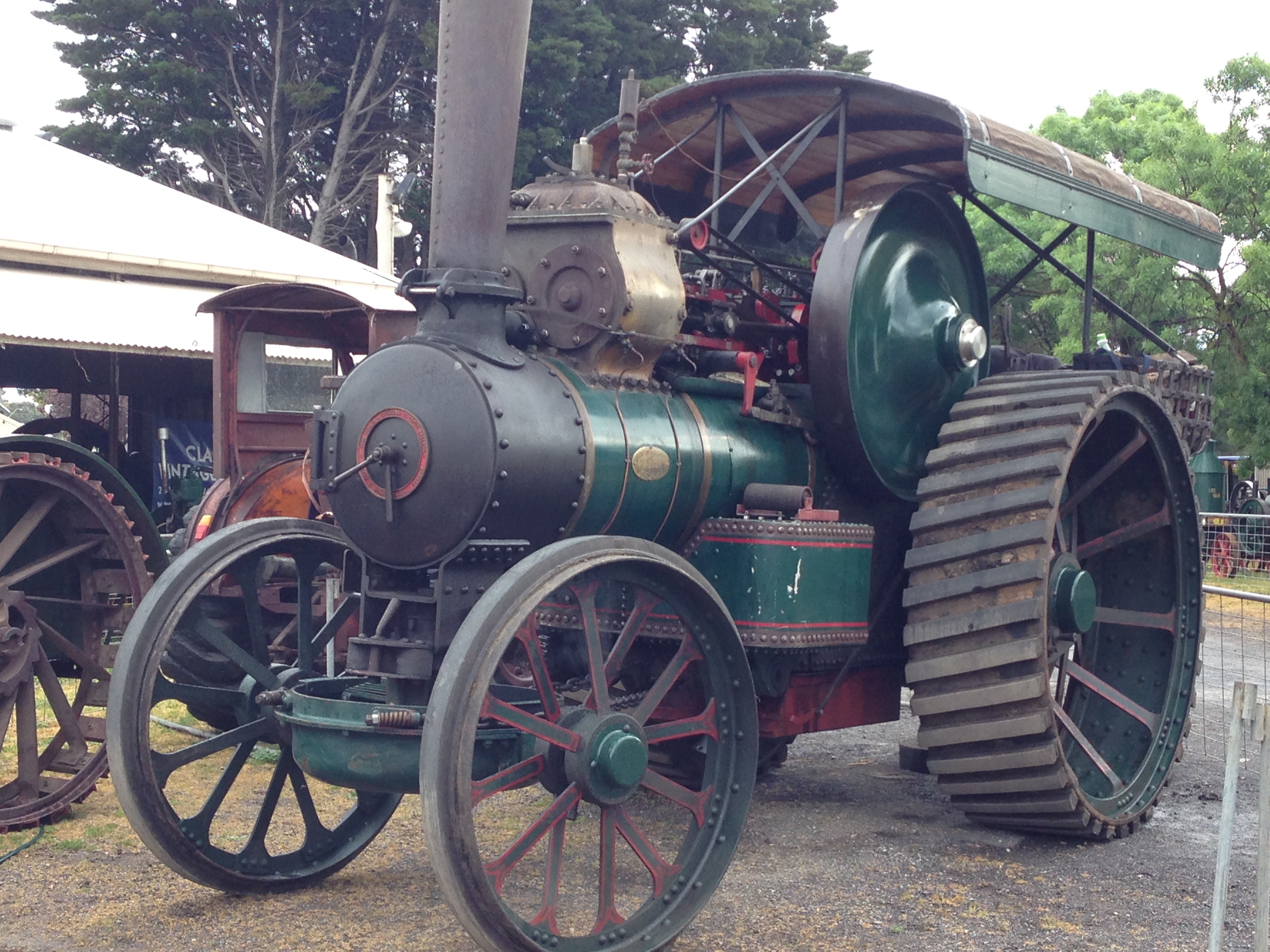
FOWLER R3 TRACTION ENGINE
Start of the parade of tractors at the Geelong Show. Graeme and John driving the Fowler R3. Video by Stuart.
Error
This video doesn’t exist
October 21, 2017
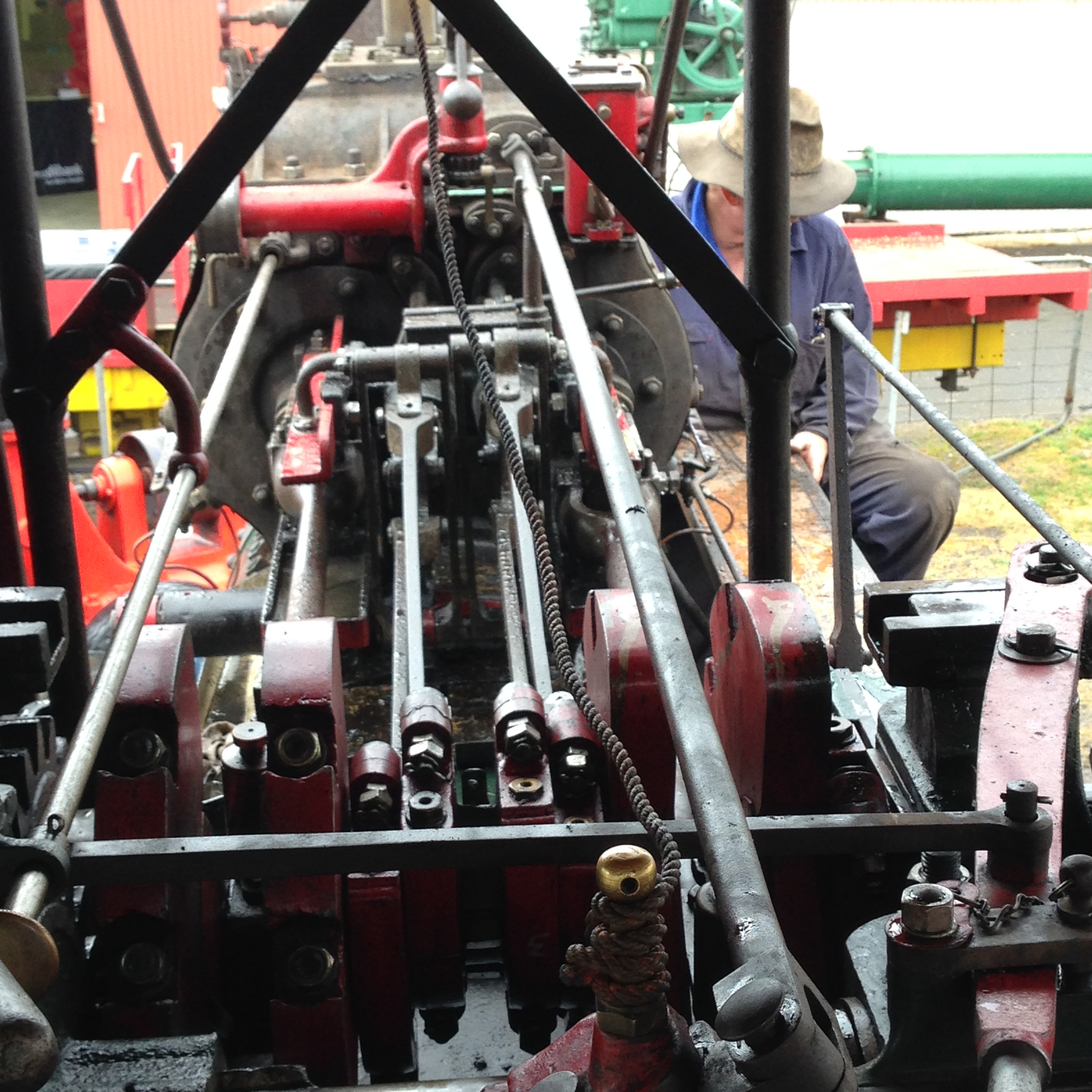
Fowler R3 at The Geelong Show
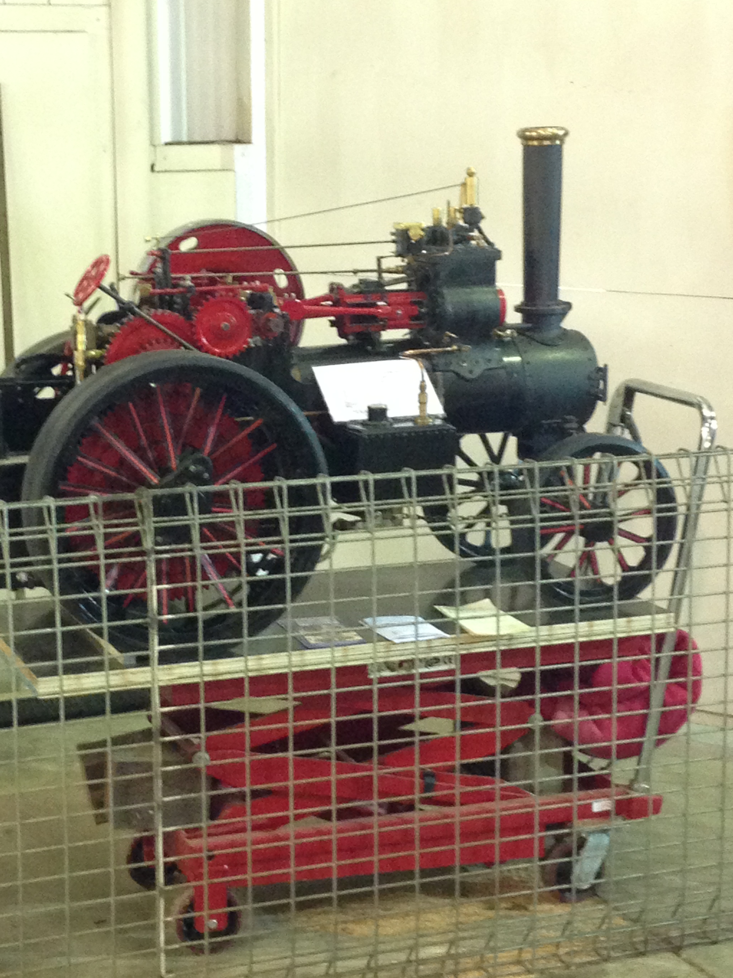
I took my Fowler R3 3″ scale traction to the Geelong Show, and here it is on display.
The R3 is a bit of an uncommon traction engine, so I was rather surprised, delighted and awed to find a full size R3 on display also. Of course I met with the owner and spent a lot of time talking to him and examining the real McCoy Fowler R3. Apart from the size difference, the similarities were striking. Even the colour scheme was similar. And the full size machine was a heavy haulage model whereas mine is a road locomotive.
I found the numbers were interesting
weight 250kg/18tonnes
length 1.5m/ 6m
towable load 250kg/60 tonnes
cylinders 2/2
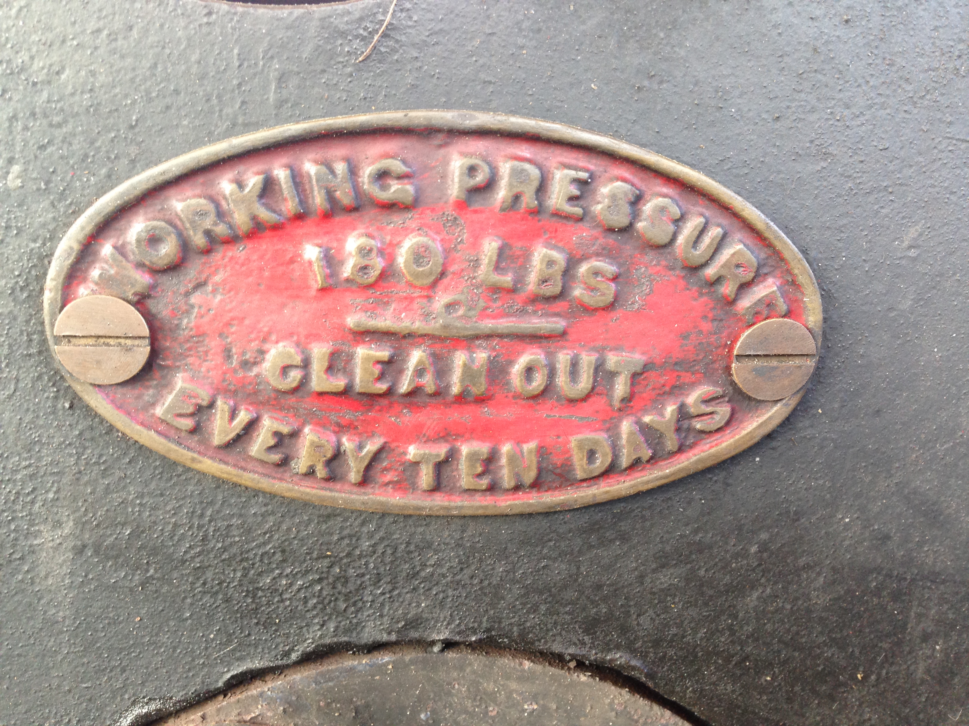
boiler pressure 100psi (copper)/180psi (riveted iron)
year of build 2016/1911
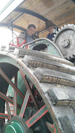
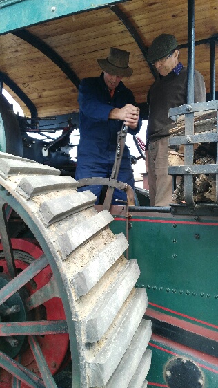
Me, getting a driving lesson from the owner, Graeme Brown
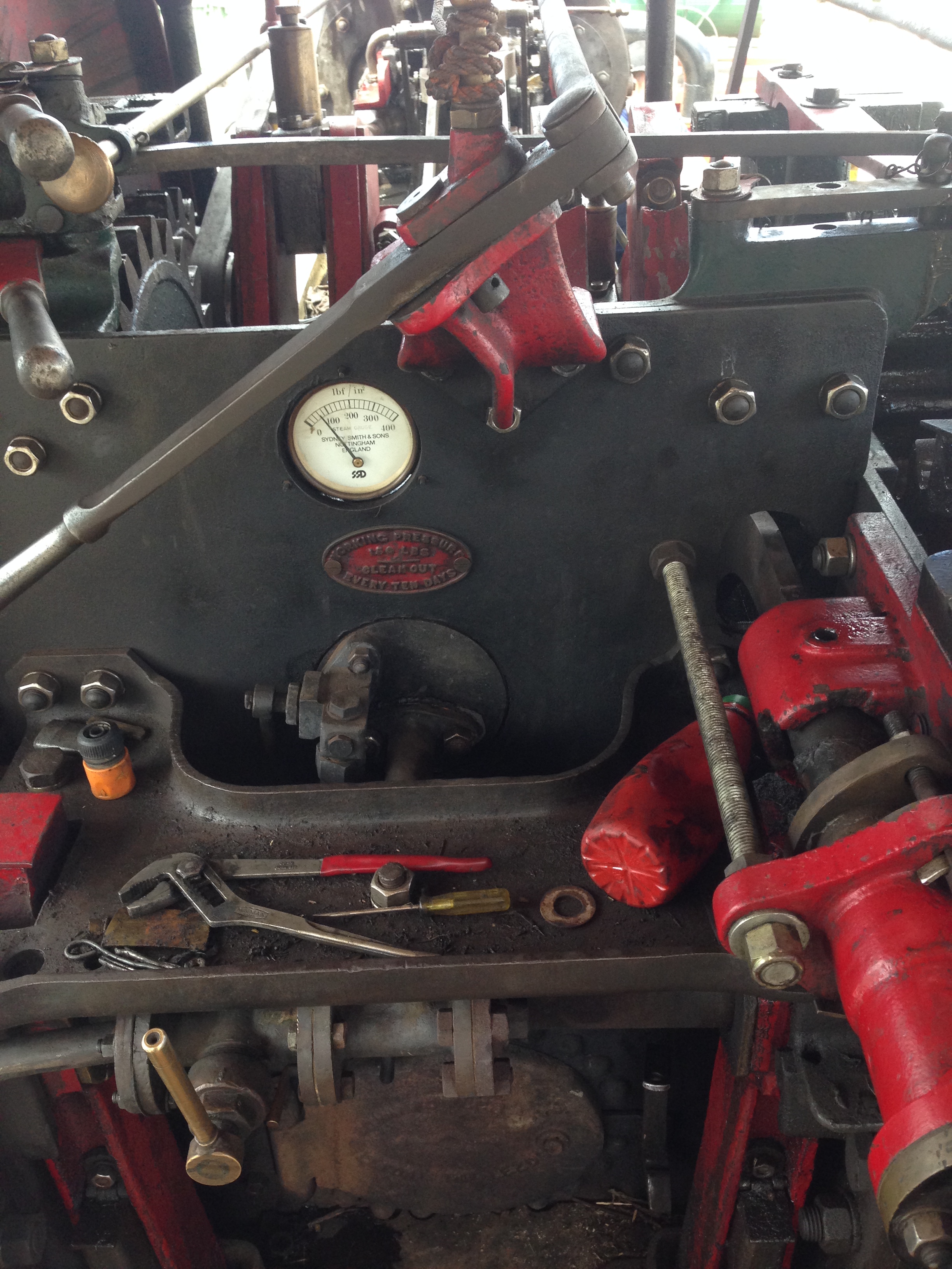
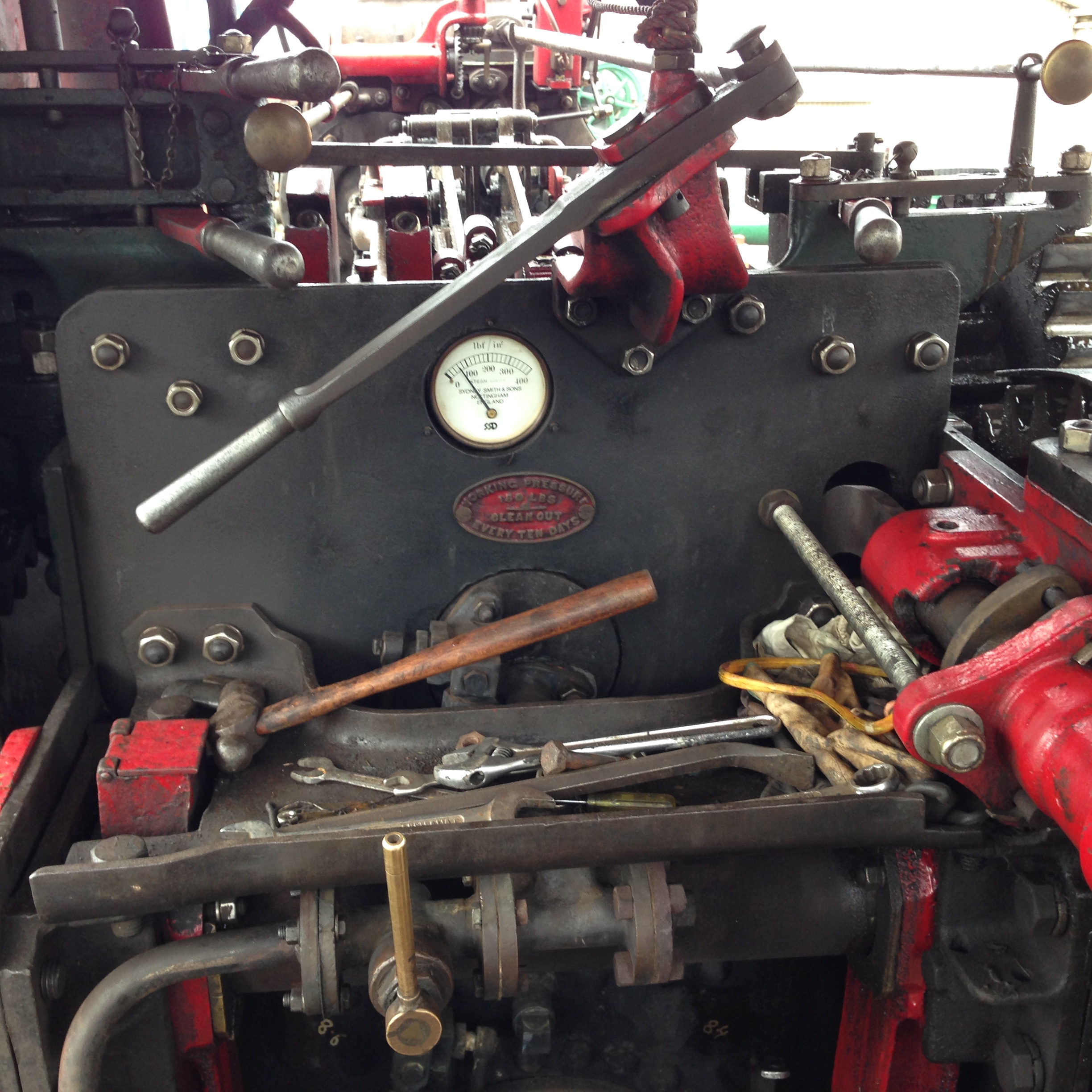
The firebox door, throttle, looking forward
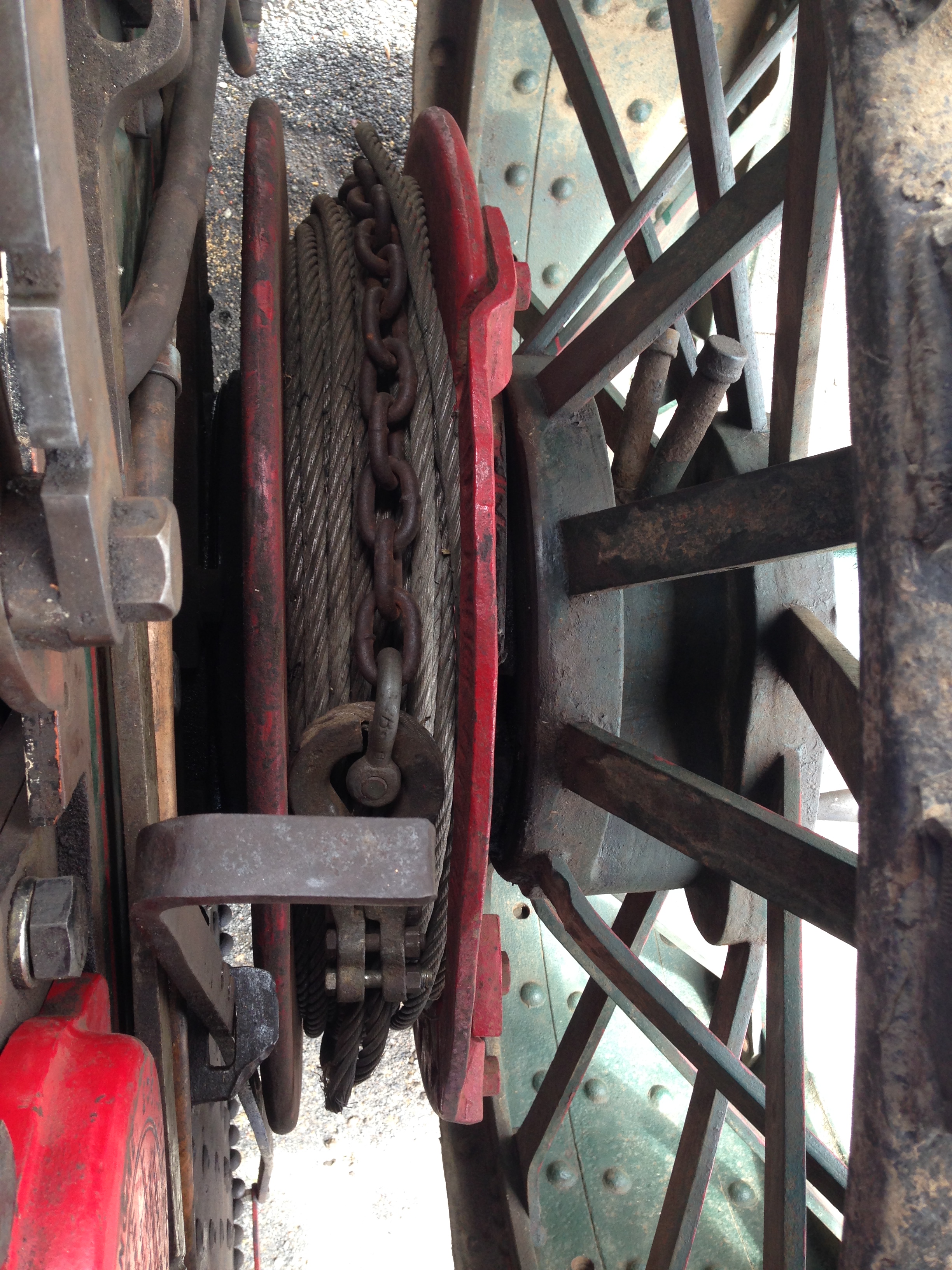
Winch
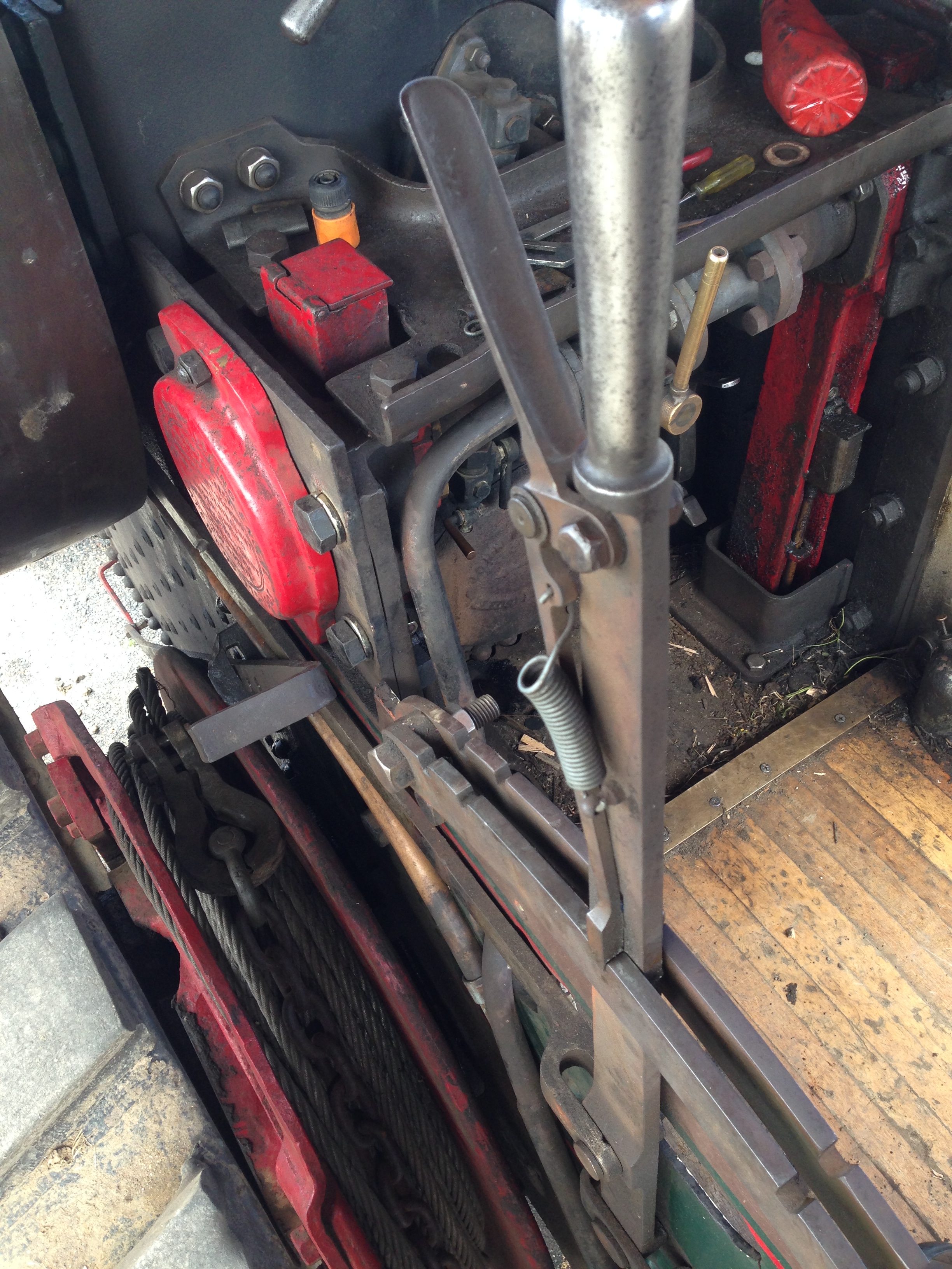
Forward/reverse lever
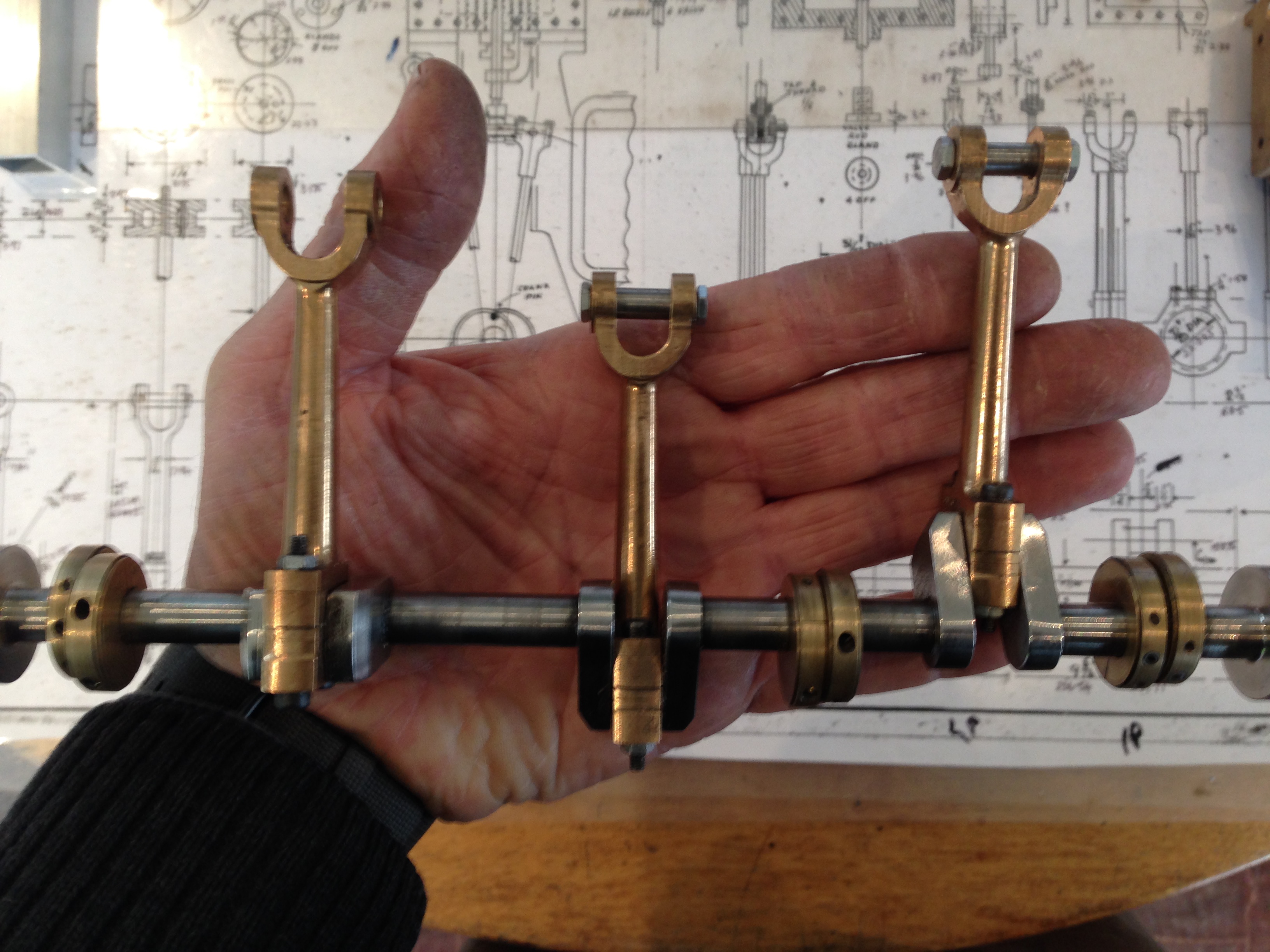
Water pump, crankshaft driven
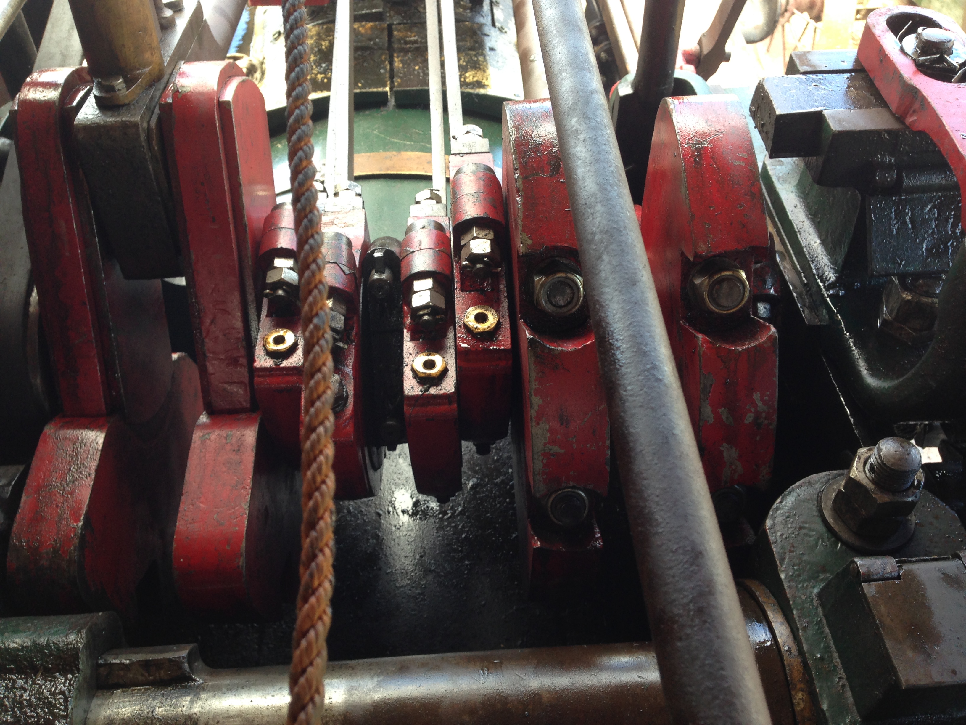
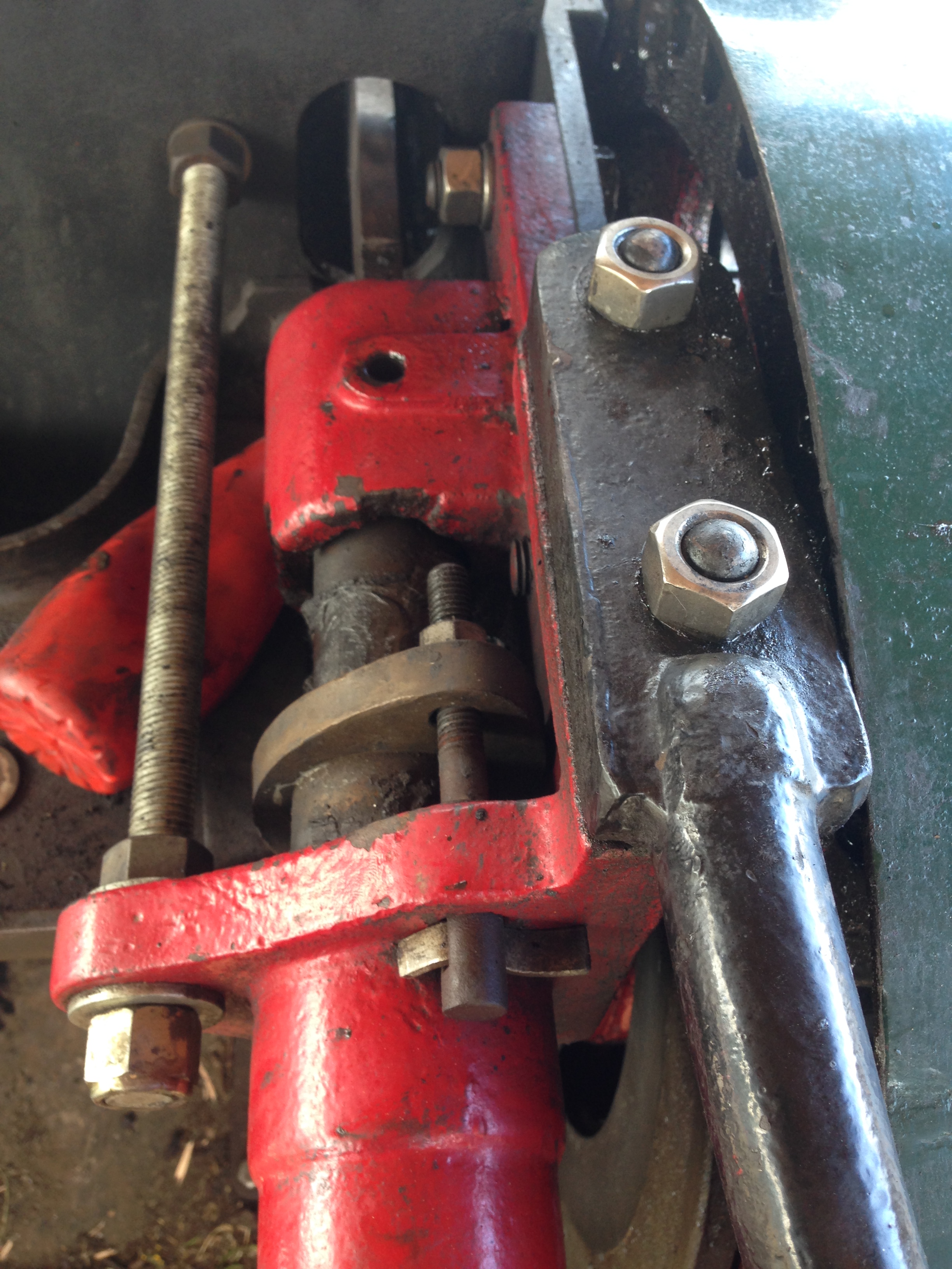
crankshaft with its cluster of big ends and valve rod eccentrics.
Con rod big end hardware
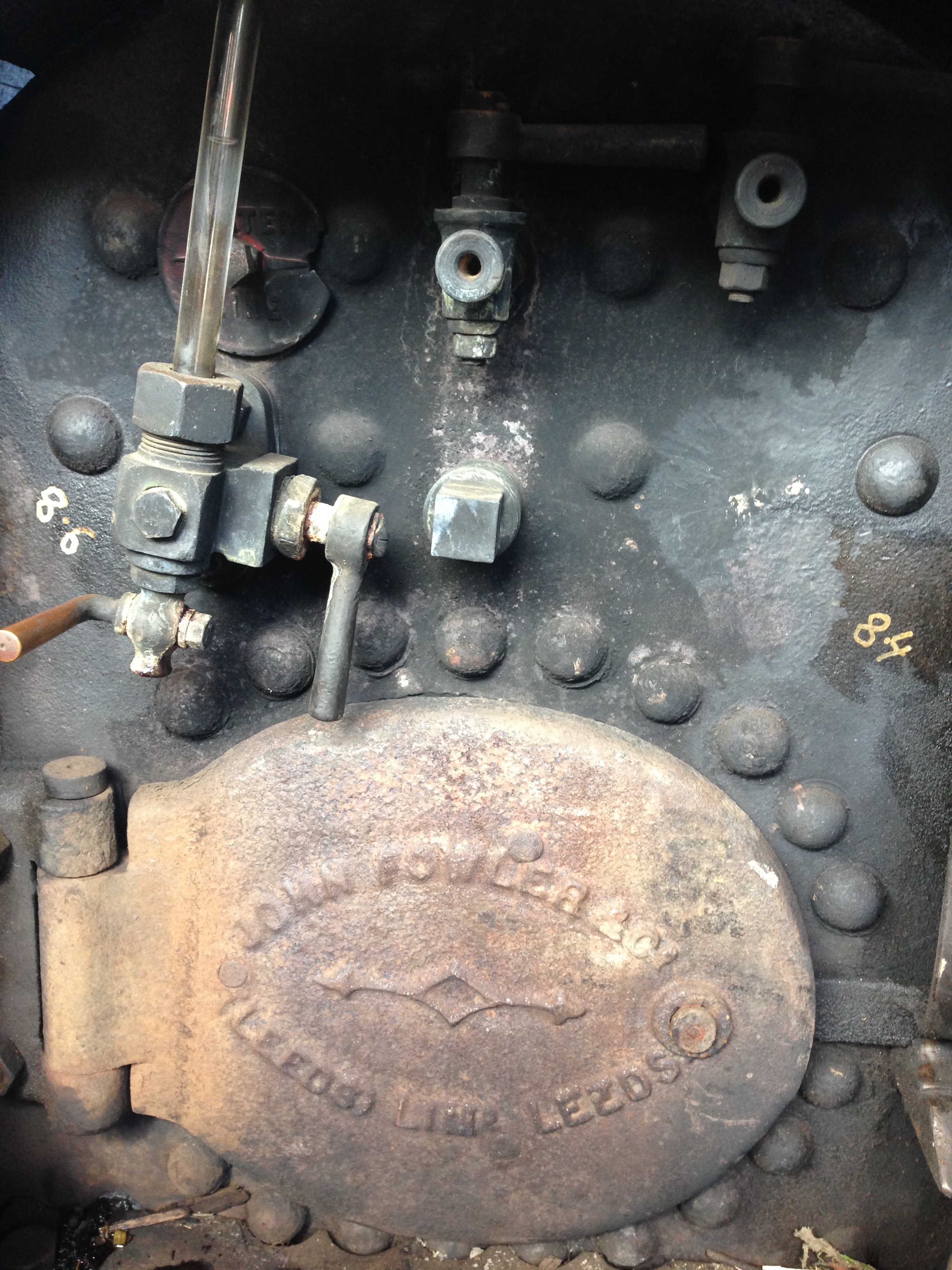
Fire box door and water level sight glass
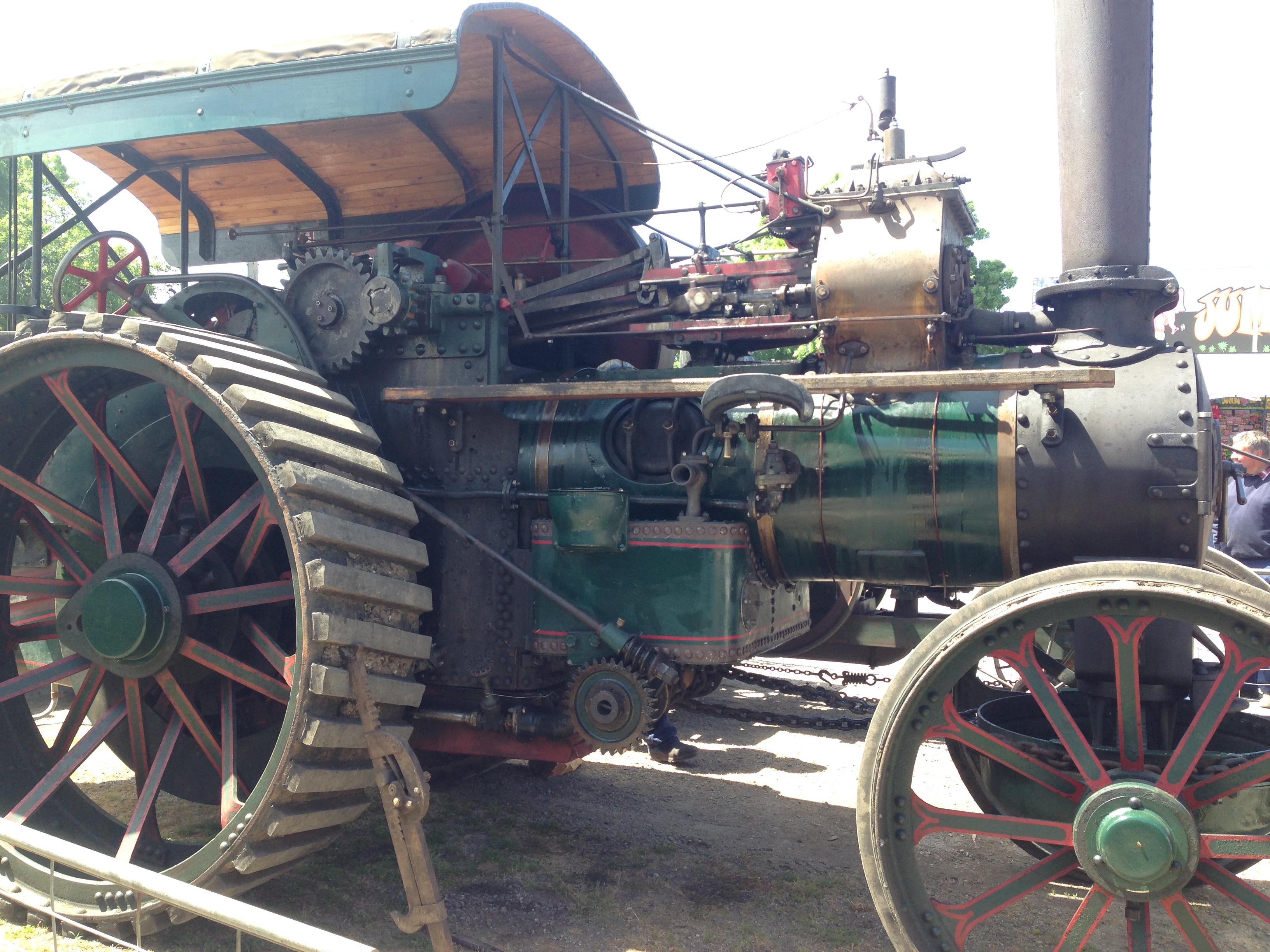
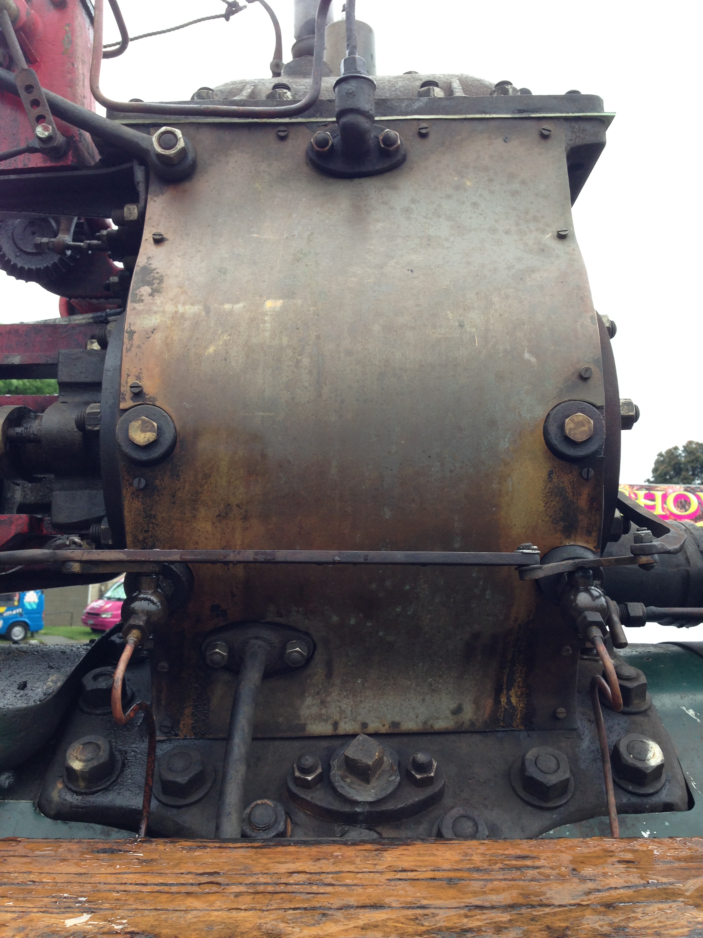
Fowler R3 heavy haulage engine. spent most of its working life in and around Ballarat, Victoria, Australia
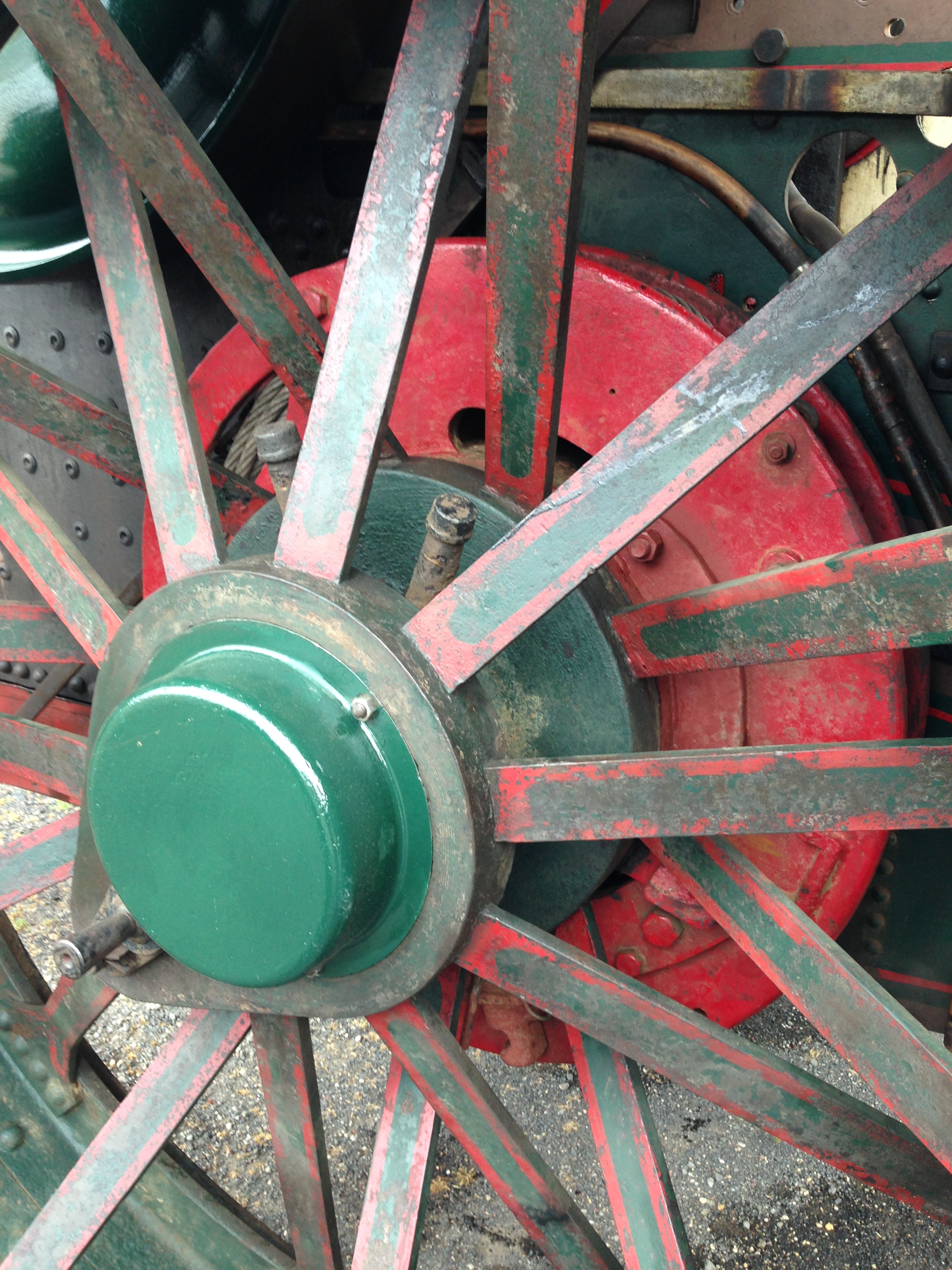
Rear wheel hub and winch
This could be a photo of my engine, but it is not
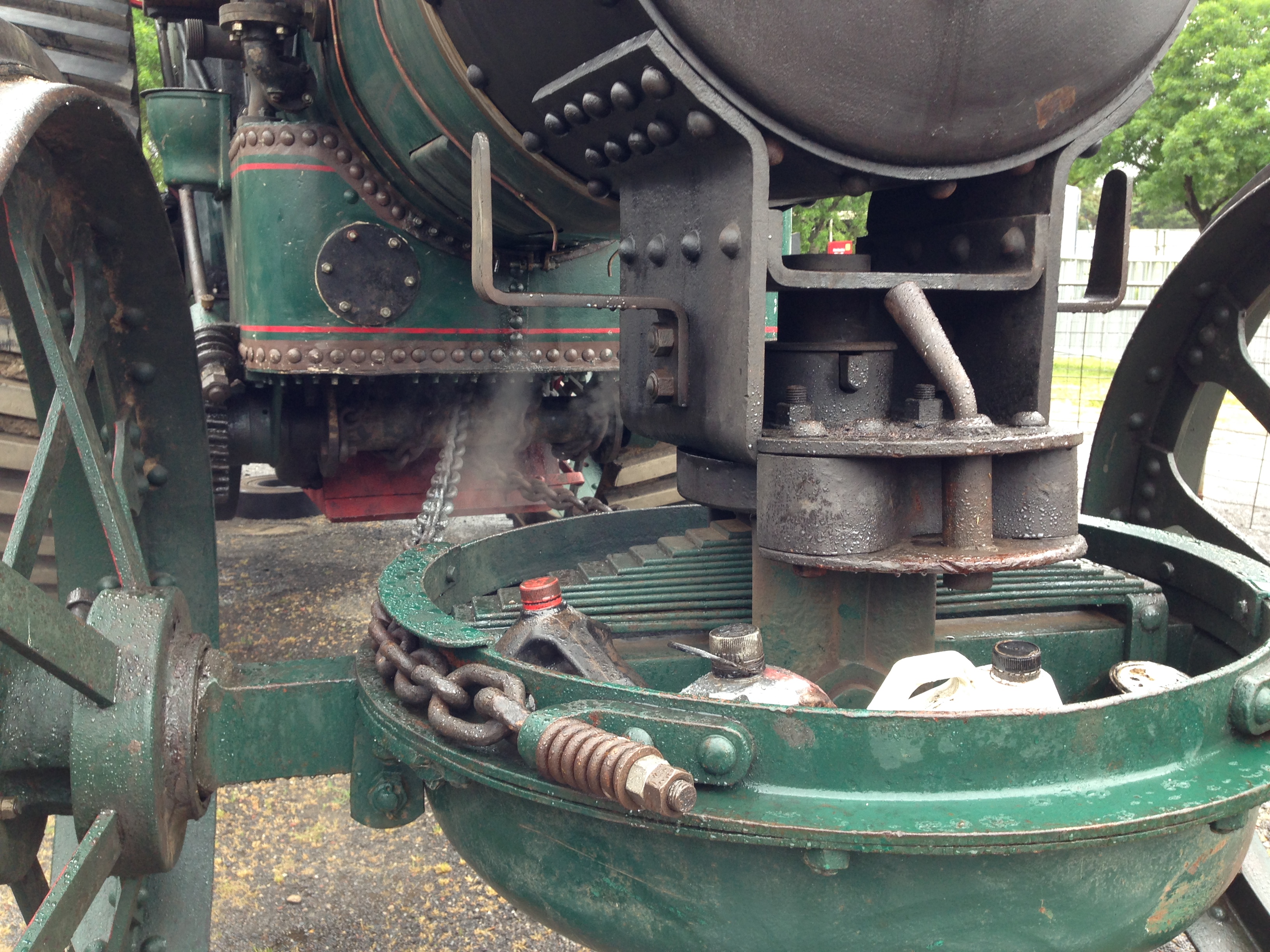
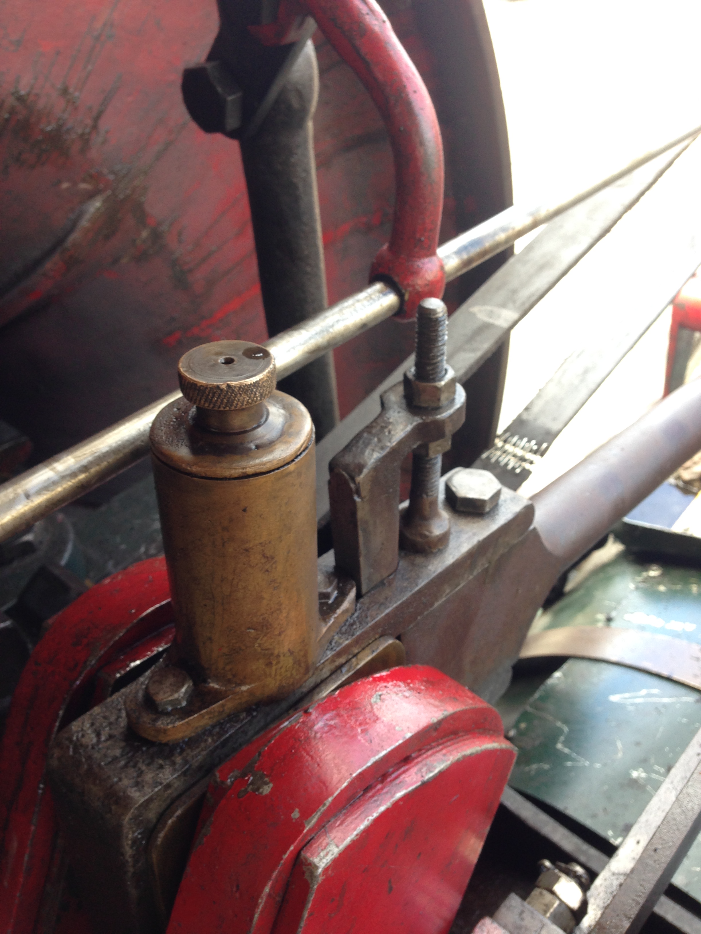
Lubricant and tool storage area. Actually the front suspension and steering drum. I imagine that the springs are to protect the gear teeth.
Not sure that the brass cylinder cover is kosher.
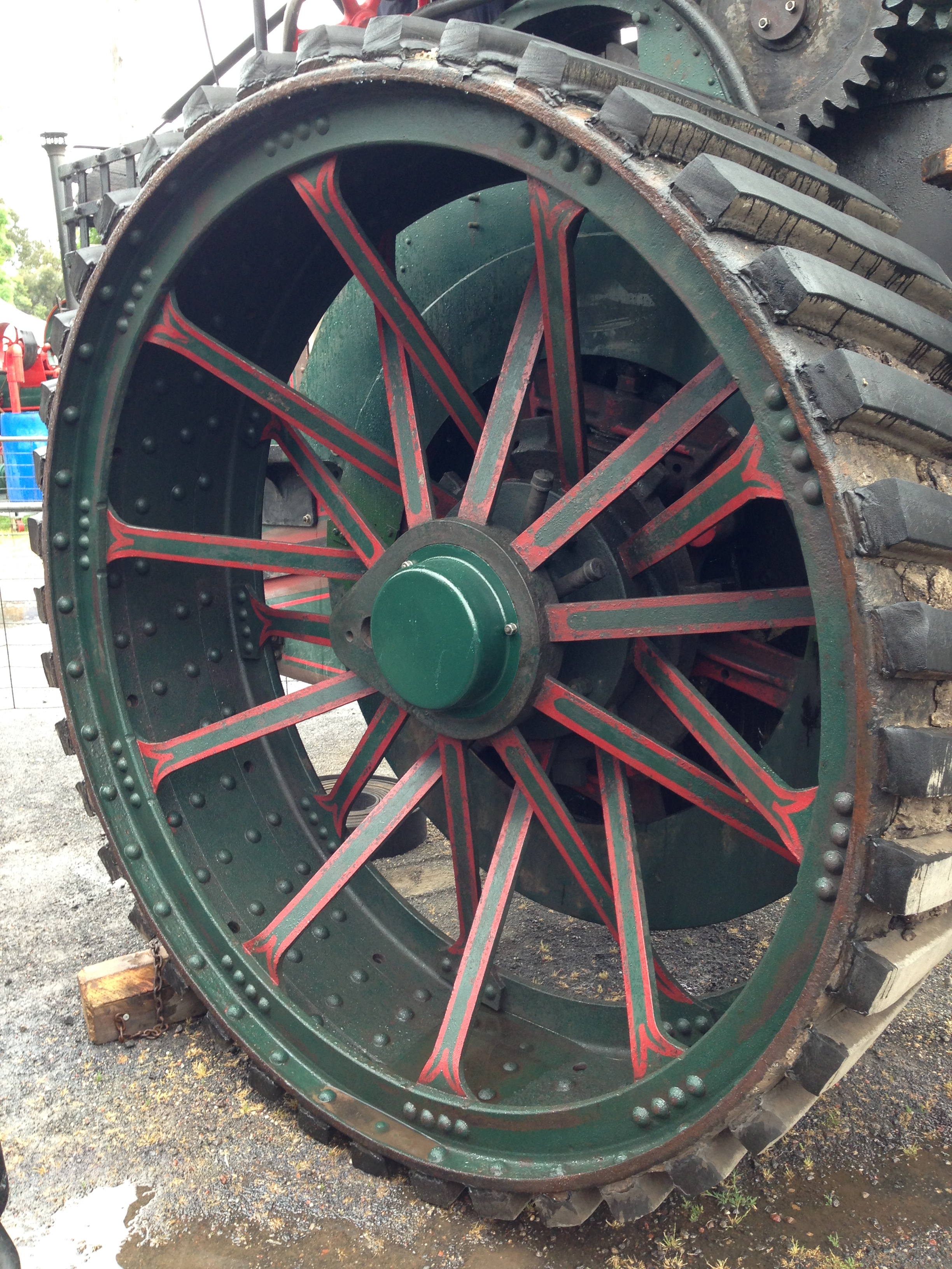
The wheels hardly dented the grass during the grand parade.
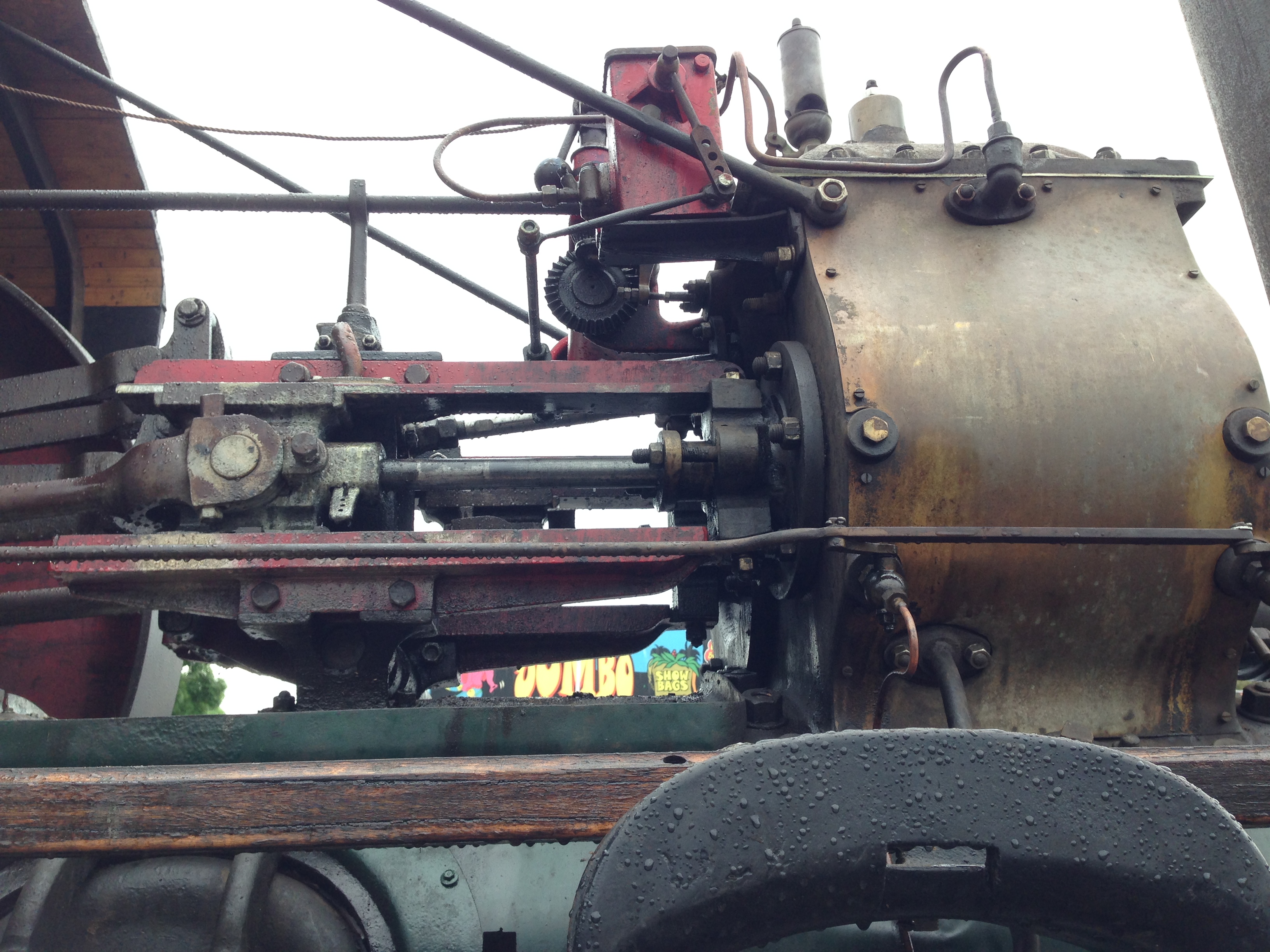
The engine mechanicals, oiler, whistle, and hose support.
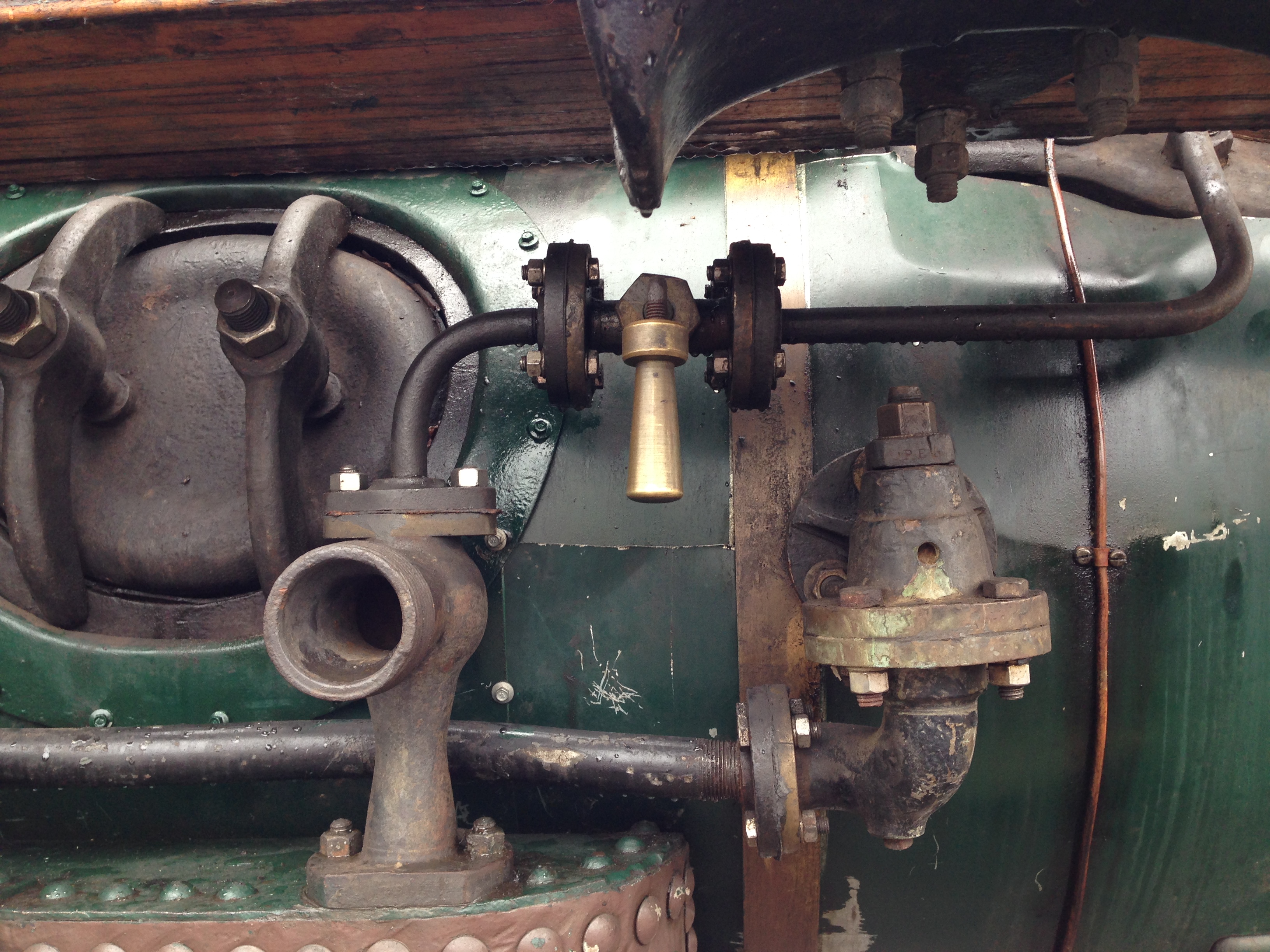
Boiler inspection hatch, and water intake.
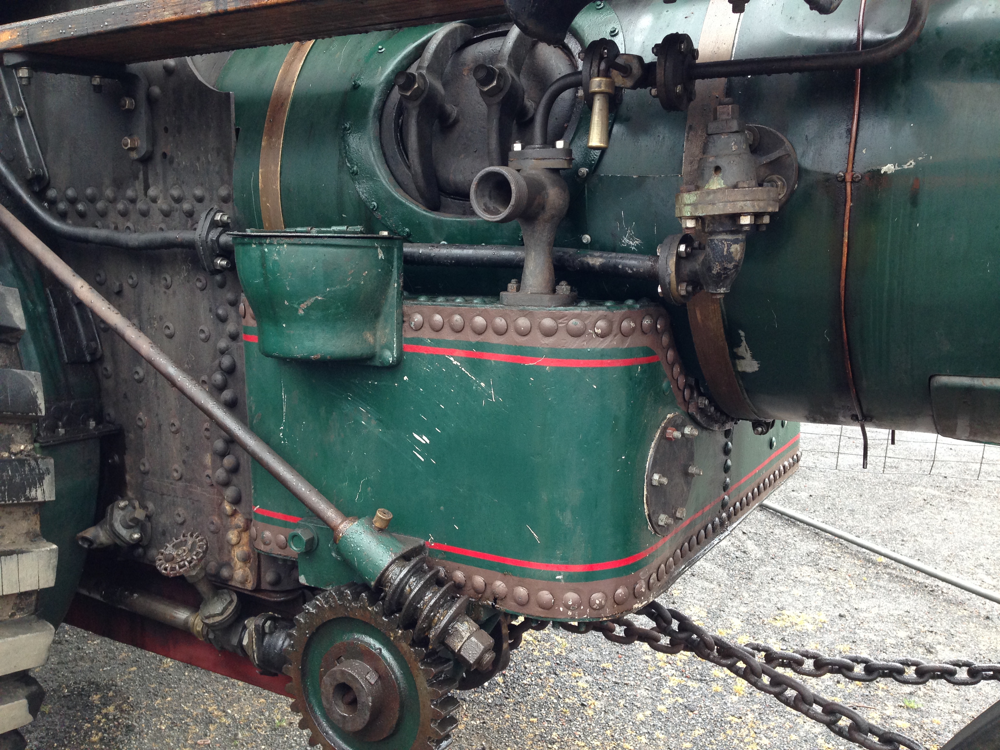
Belly tank, steering gear
The engine could be used as a cathedral reliquary
And a series of non-edited videos, to recapture some magic moments.
October 16, 2017
More Triple Photos
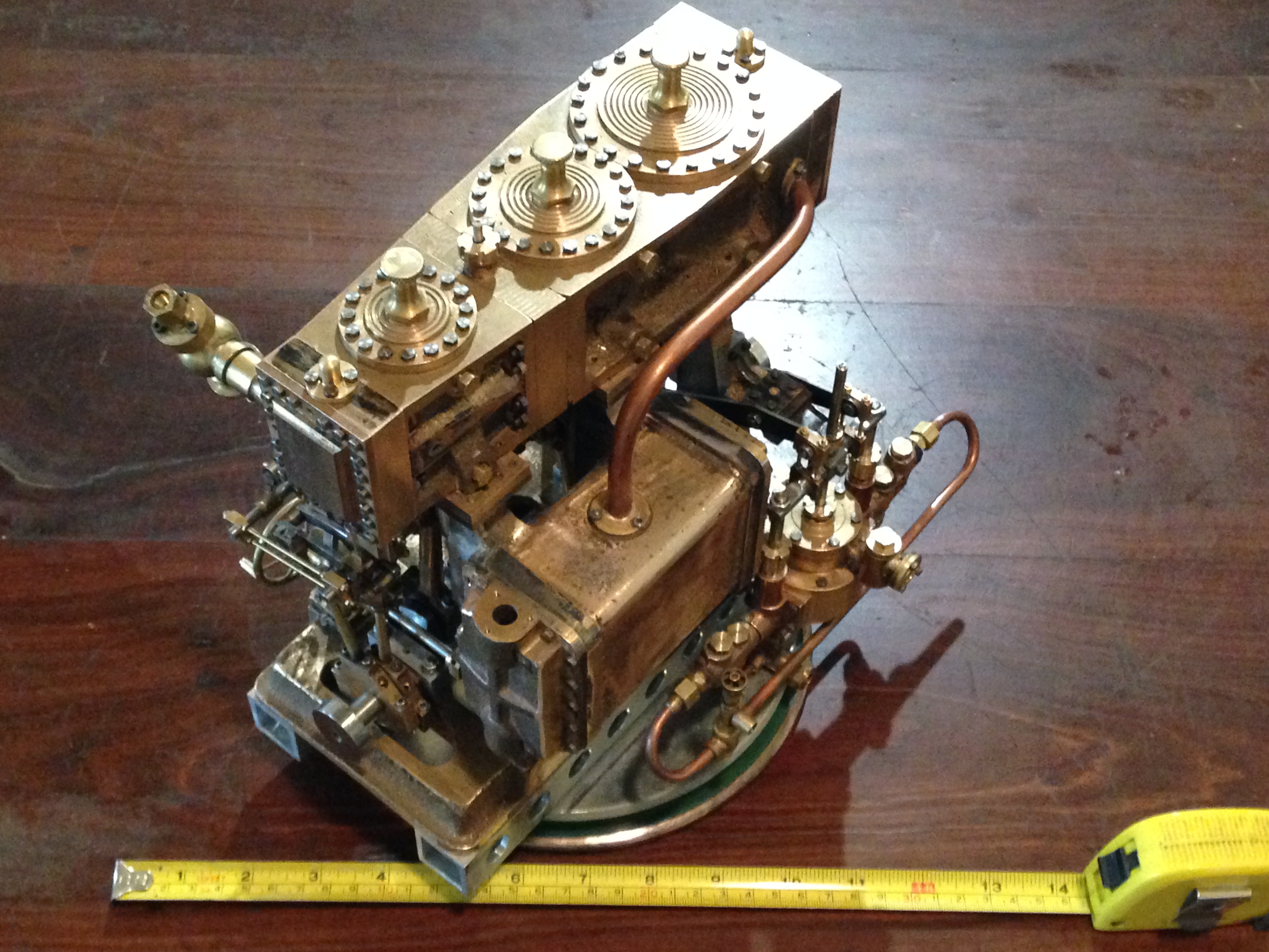
Reader Richard suggested that I include a ruler in some of the triple photos, for a sense of scale, so here it is.
It is approx 300mm long 200mm wide and 270mm high. Weighs 12.4 kg.
October 15, 2017
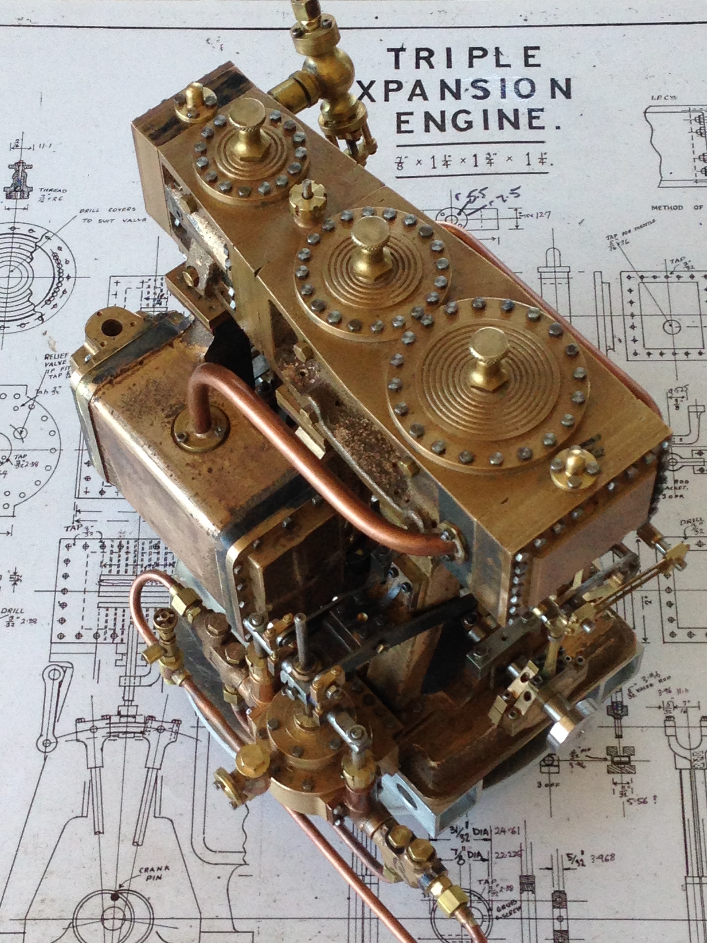
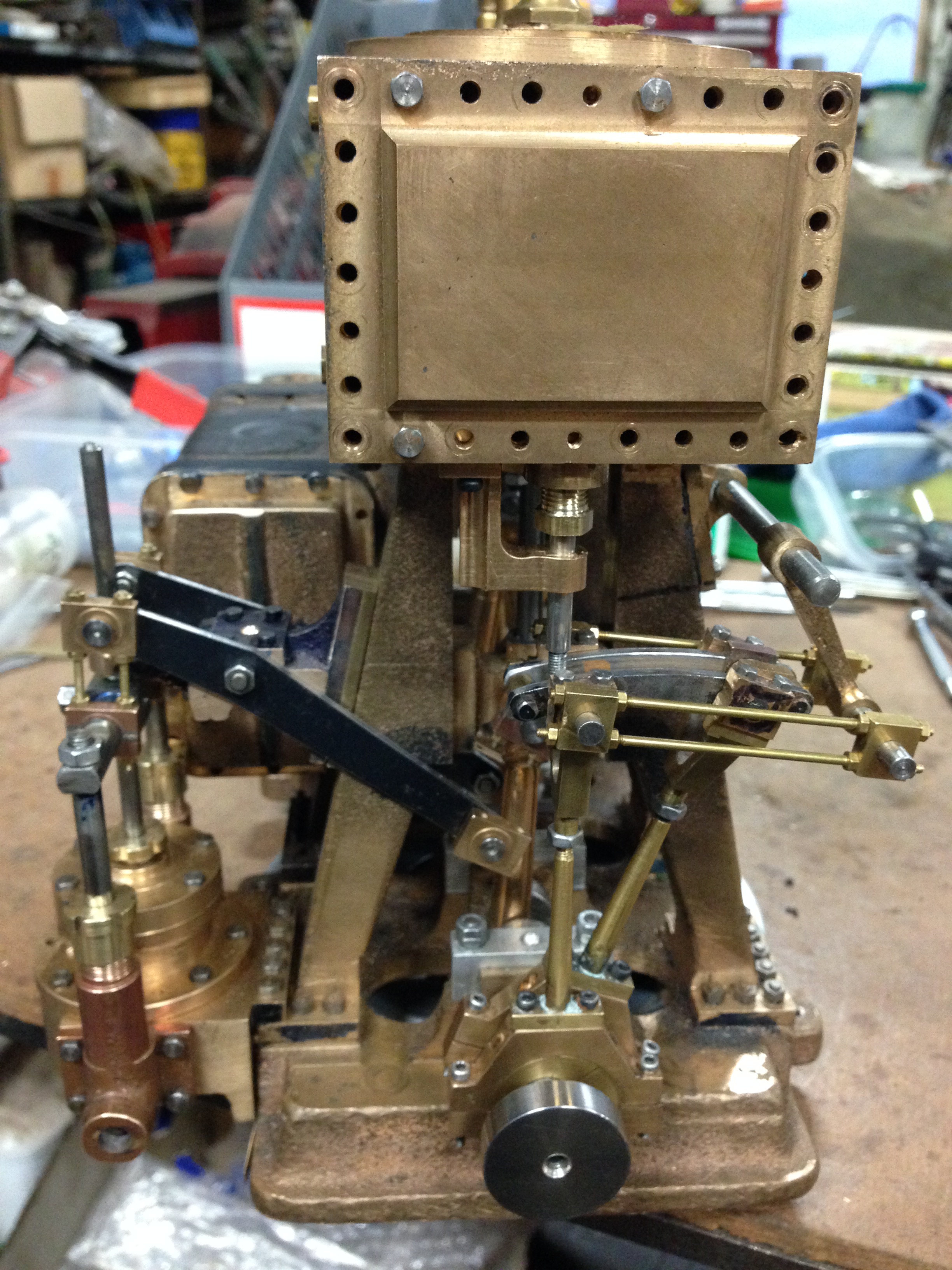
Triple Expansion Engine Update
Well, almost another whole year has elapsed, and still the triple is not finished. Come December, and that will be 3 years that this project has occupied my thoughts and workbench. With a few other projects in between.
Last week I assembled the components, in preparation for the Geelong Show. GSMEE is a bit light on for new models, and it was suggested that the triple might fill some shelf space, despite being unfinished.
So I bolted it together. All 429 fasteners! And stood back and admired it. It really is quite impressive, complex, and interesting. So I took some pics.
This is the condenser side, and the Edwards pump
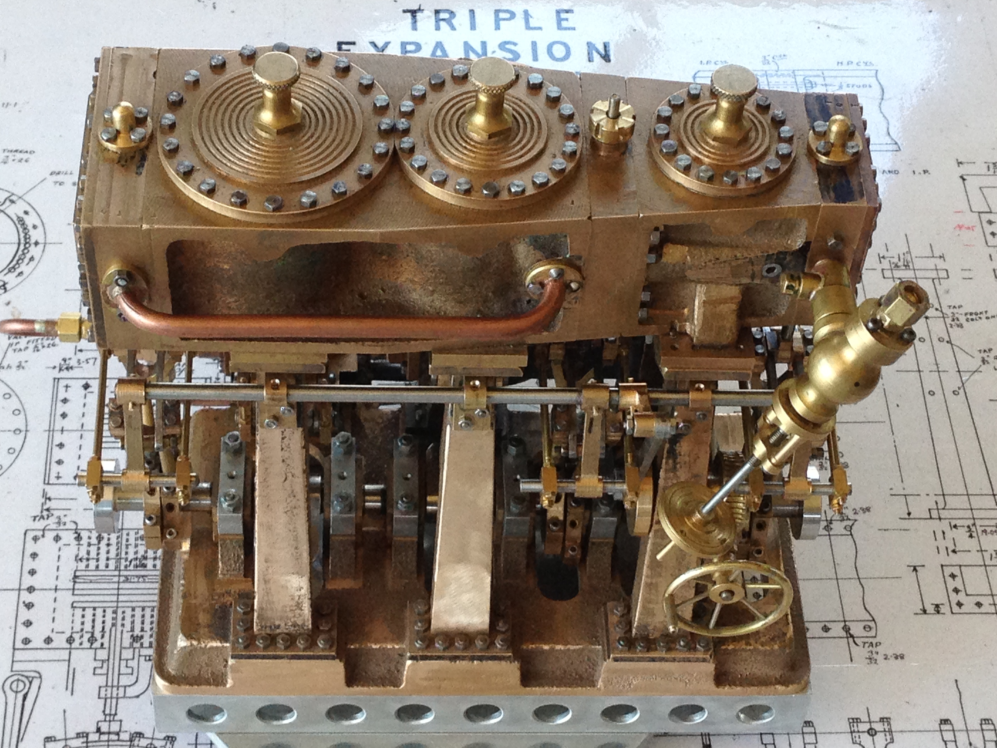
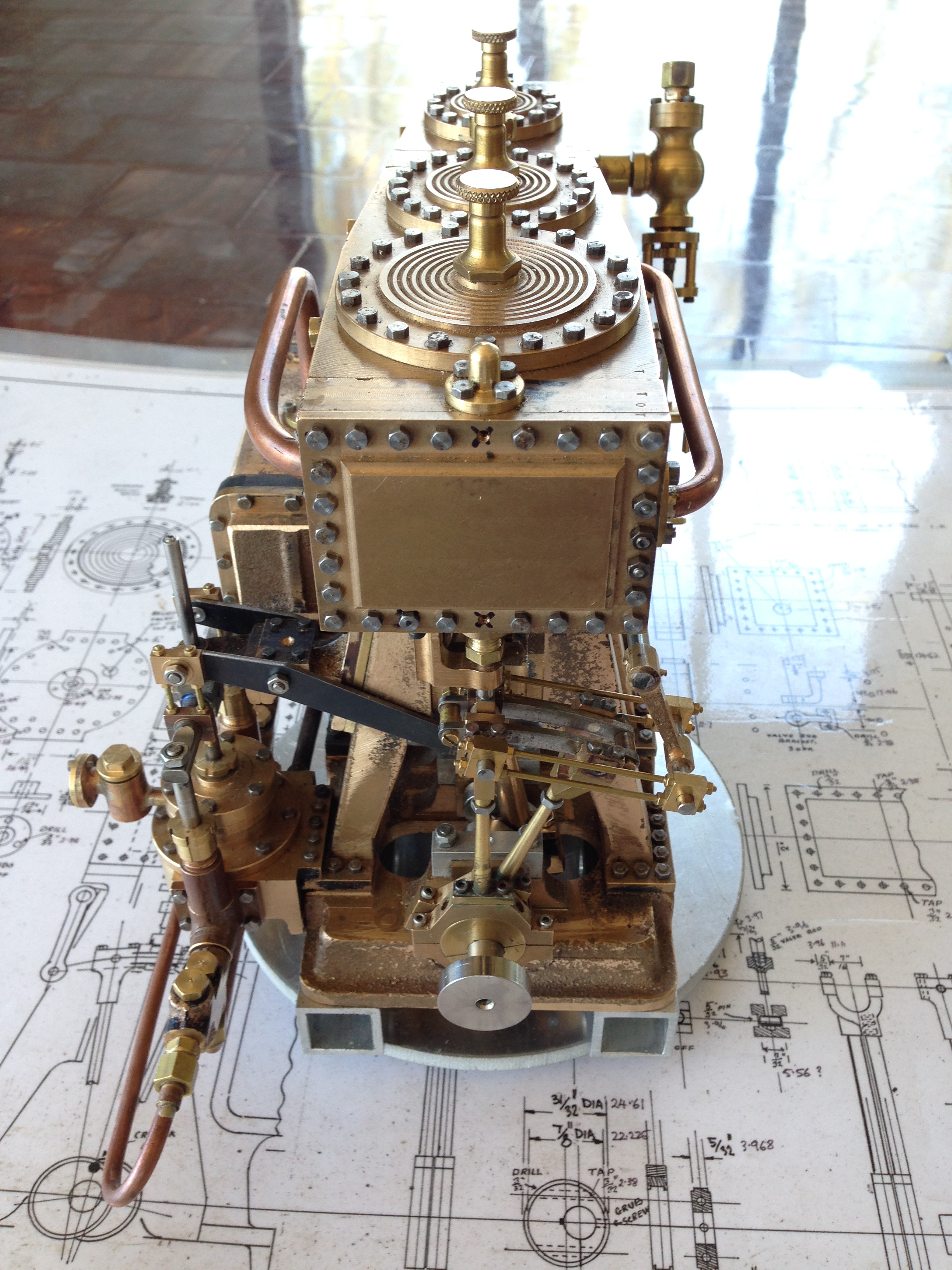
The other side is a bit lessy fussy, showing the steam inlet valve, the Stephenson’s links, weigh shaft and controls.
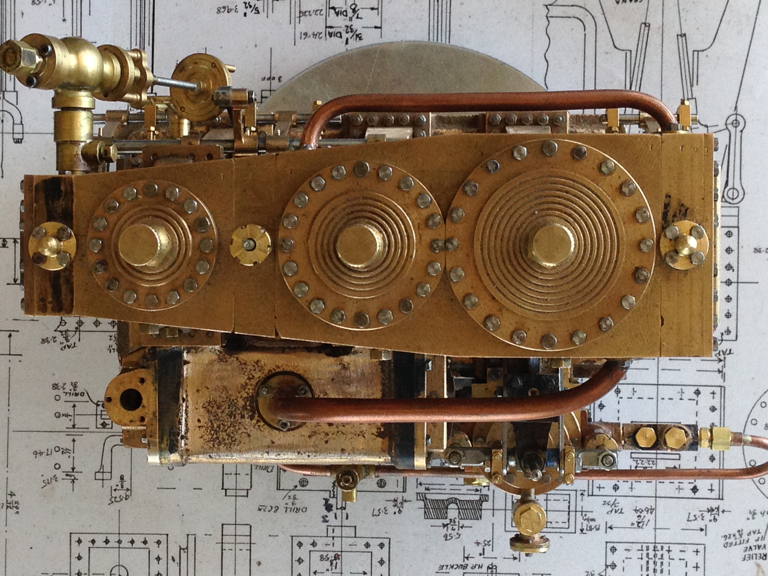
And the top, showing some of those 429 fasteners,
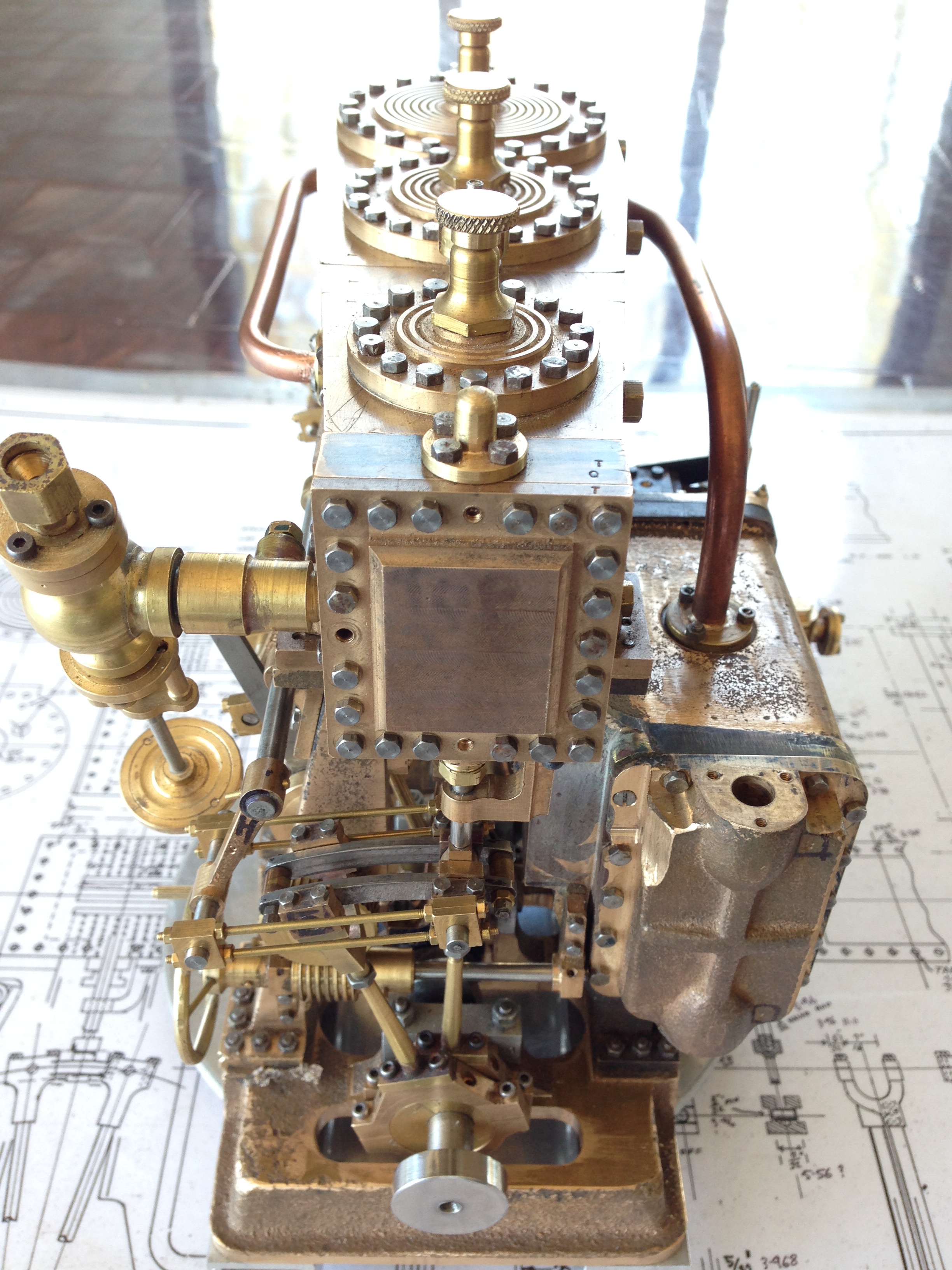
The high pressure valve chest cover. I will fill those holes where bolts cannot go.
And the low pressure end, and links for the pump.
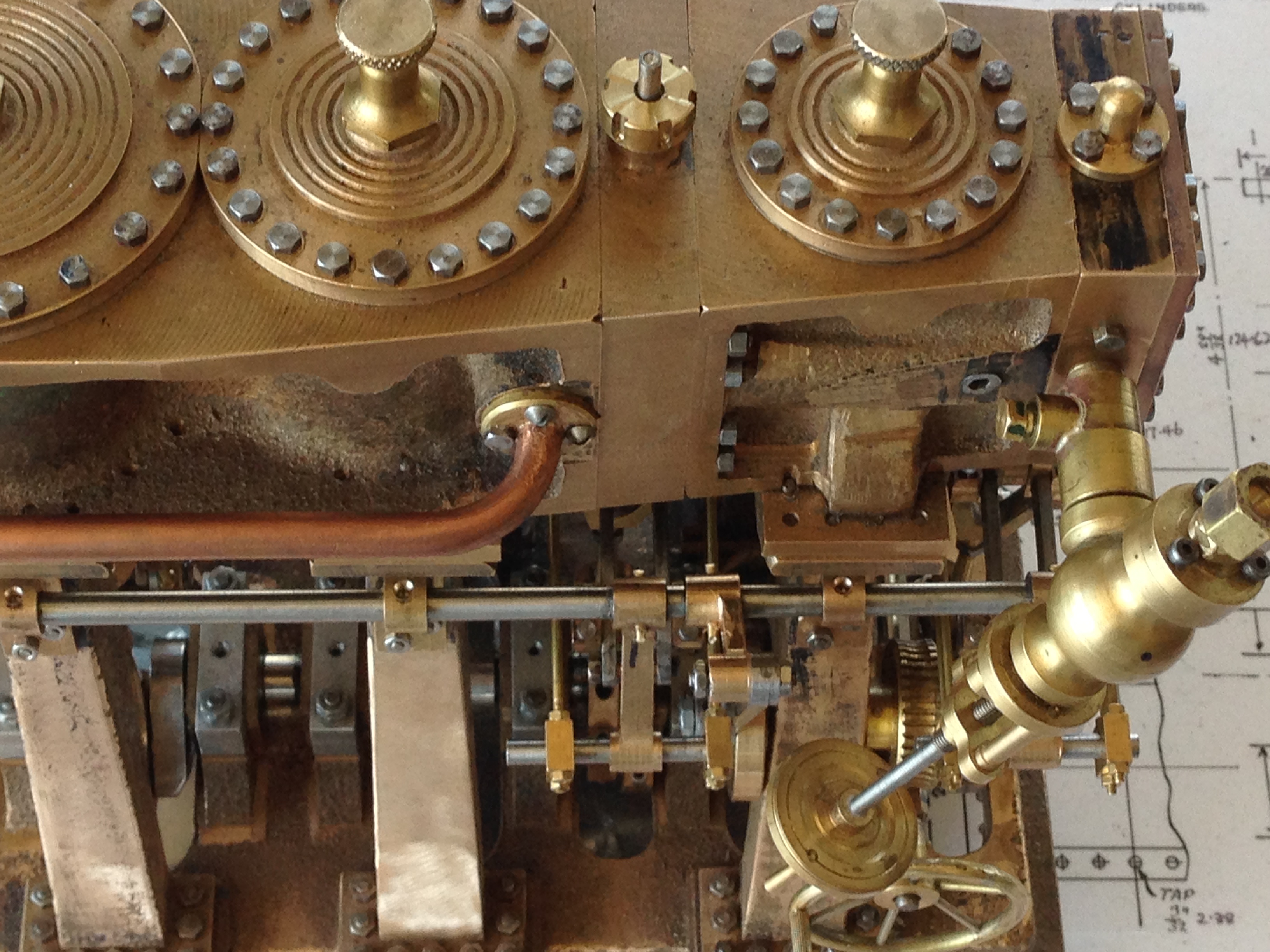
And a close up of the steam valve and weigh shaft.
Not quite ready to run it yet.
It needs side covers for the cylinder block, drain cocks for the cylinders, and general freeing up. It is still very tight.
Not to mention painting. I expect that I will paint this one. No idea of colours yet.
August 20, 2017
Steam Trains
Two of my grandchildren are identical twins. Here is a recent photo of one of them. Not much point showing a photo of the other one. He is identical.
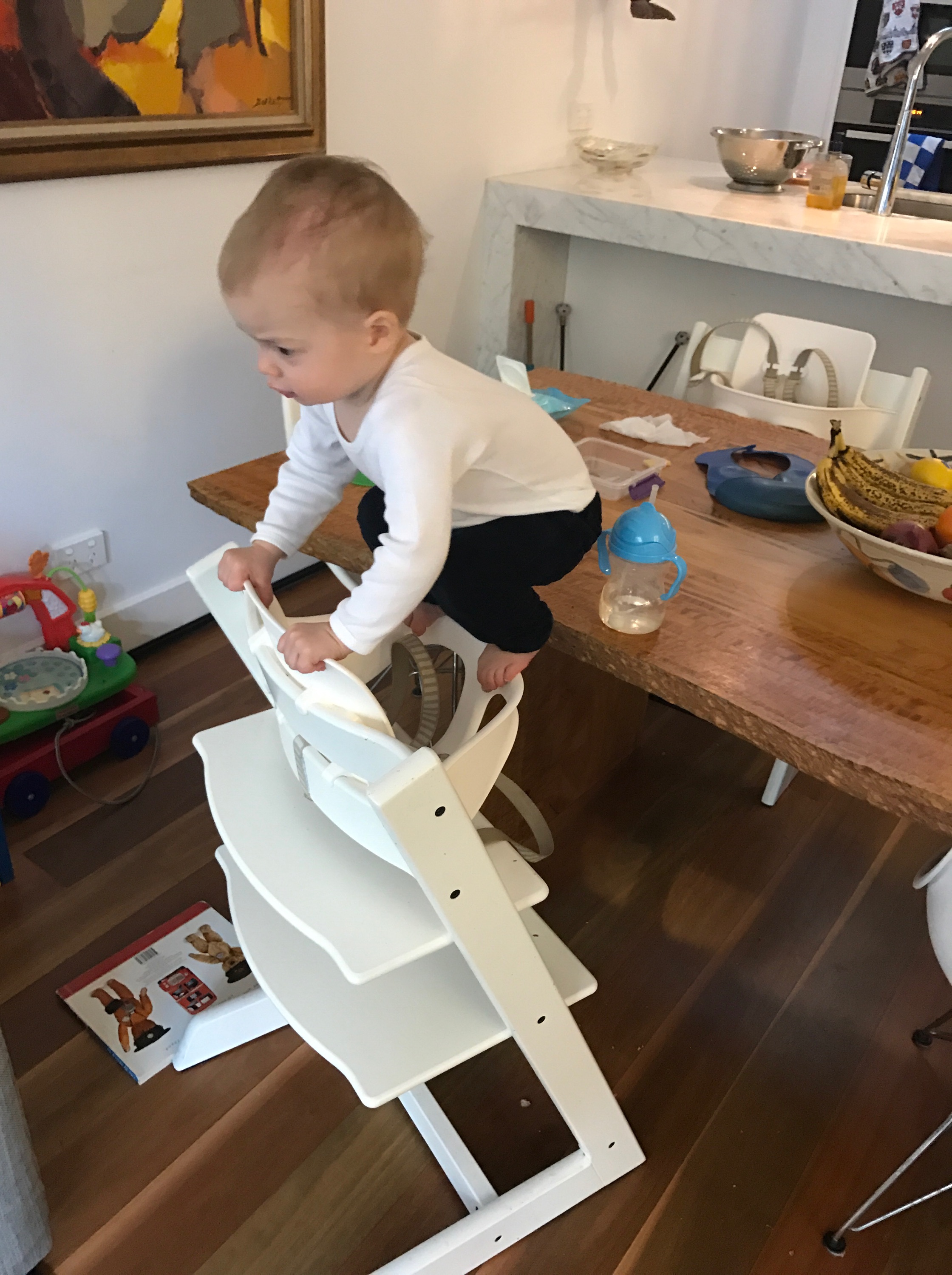
Not sure which one this is. They really are identical. He is planning to join a circus.
Anyway, I had made a wooden train set for my other grandchildren, and my other daughter, the mother of the twins, suggested that the twins should have one also. I decided to CNC most of the parts, and it was not much more time to make two compared to one, so here they are.
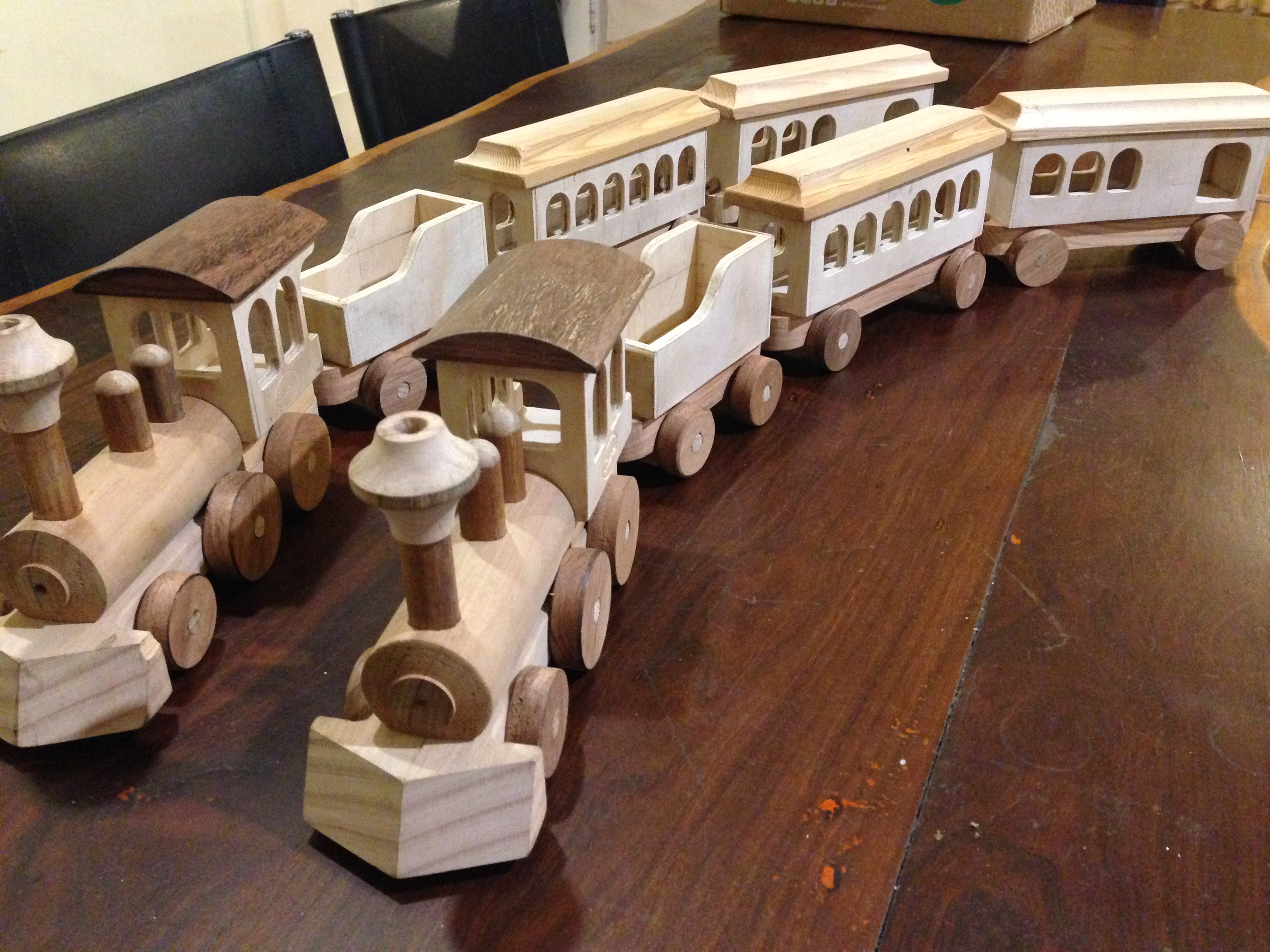
The design, slightly modified, is from a book by Jim Makowicki “Making Heirloom Toys”. The trains are ready for painting by SWMBO. She is planning to use wood dyes, and finishing with a clear laquer.
The materials are whatever I could find in my workshop, so there is an eclectic mixture of Australian hardwoods, plywood, and pine. The panels were all CNC milled, and the chimneys and domes were CNC turned.
It has been a fun project. I will post a photo when they are coloured.
August 2, 2017
Horizontal Mill Engine (HME)
The HME is our Model Engineering Club competition build for 2017. I finished making the components and tried to get it running, unsuccesfully.
So today I took it to the GSMEE morning meeting, and Rudi, who is a retired marine engineer, and has completed his own HME, took one look at mine and said that the timing was totally up the creek.
Rudi fiddled for a few minutes, and said, “it will work now”. A couple of other members doubted his assessment, but were not confident enough to put money on it.
Anyway, this afternoon I hooked it up to a small compressor (my air brush compressor actually), and at 10psi it started to move. At 16psi it was ticking over quite nicely. Then the big test, throwing it into reverse. And hallelujah! It reversed.
Seeing an engine working, which you have made yourself, is an immensely satisfying moment.
This one still has some finishing jobs to be completed. Like sealing the joins against steam leaks. And a bit more polishing. And maybe a name plate. And there is an annoying knock which might disappear on steam. But if not, I might need to re-make one of the bearings.
But it goes!! Yay!!
June 8, 2017
A Base for the triple, and some oil holes…
Thinking about the options for a base for the triple expansion marine steam engine..
I looked at every photo I could find on the net, and thinking about whether I want to be historically accurate, or just really solid, or a bit interesting with an historical flavour.
At this stage, the decision is not set in concrete, but I am going with the last option. Photos later in this post.
But first, I have pulled all of the major components apart, and I am spending time doing a few of those jobs which I had been avoiding because they are difficult and imprecise, and if they go badly it will be a major disaster at this stage. Like drilling the oil holes and wells for the big ends.
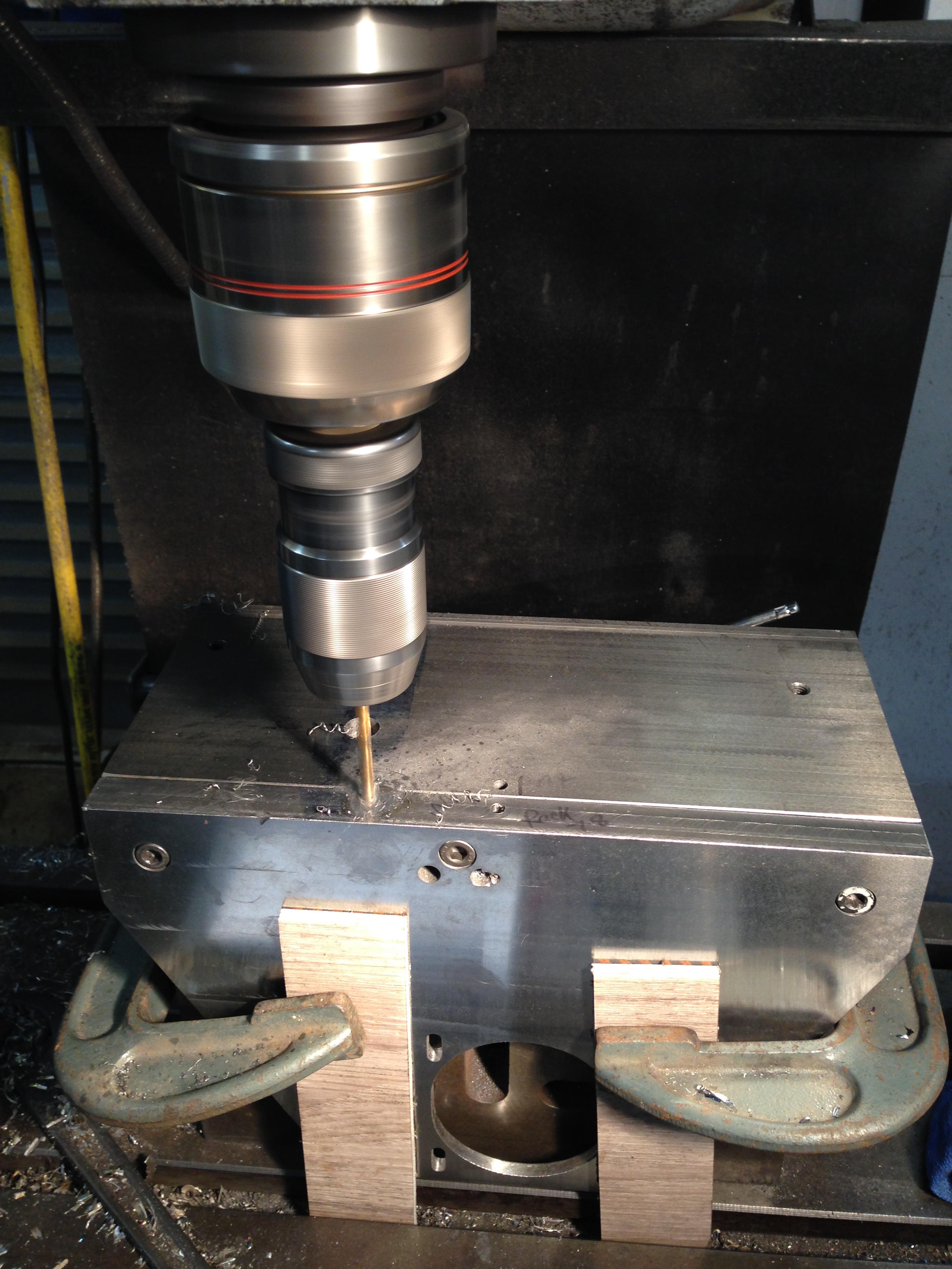
Nothing precise about this. The con rods and big end shells and bearings have been painstakingly machined, and I do not want to think about remaking them if I stuff up. And drilling into curved surfaces, with a 1.5mm drill bit…
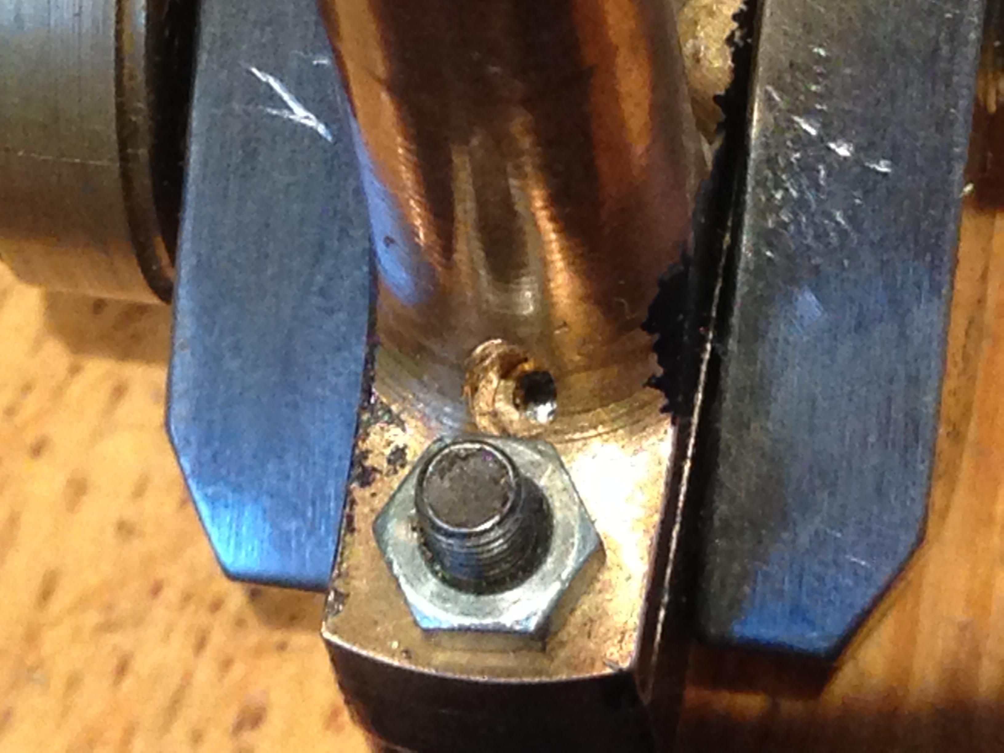
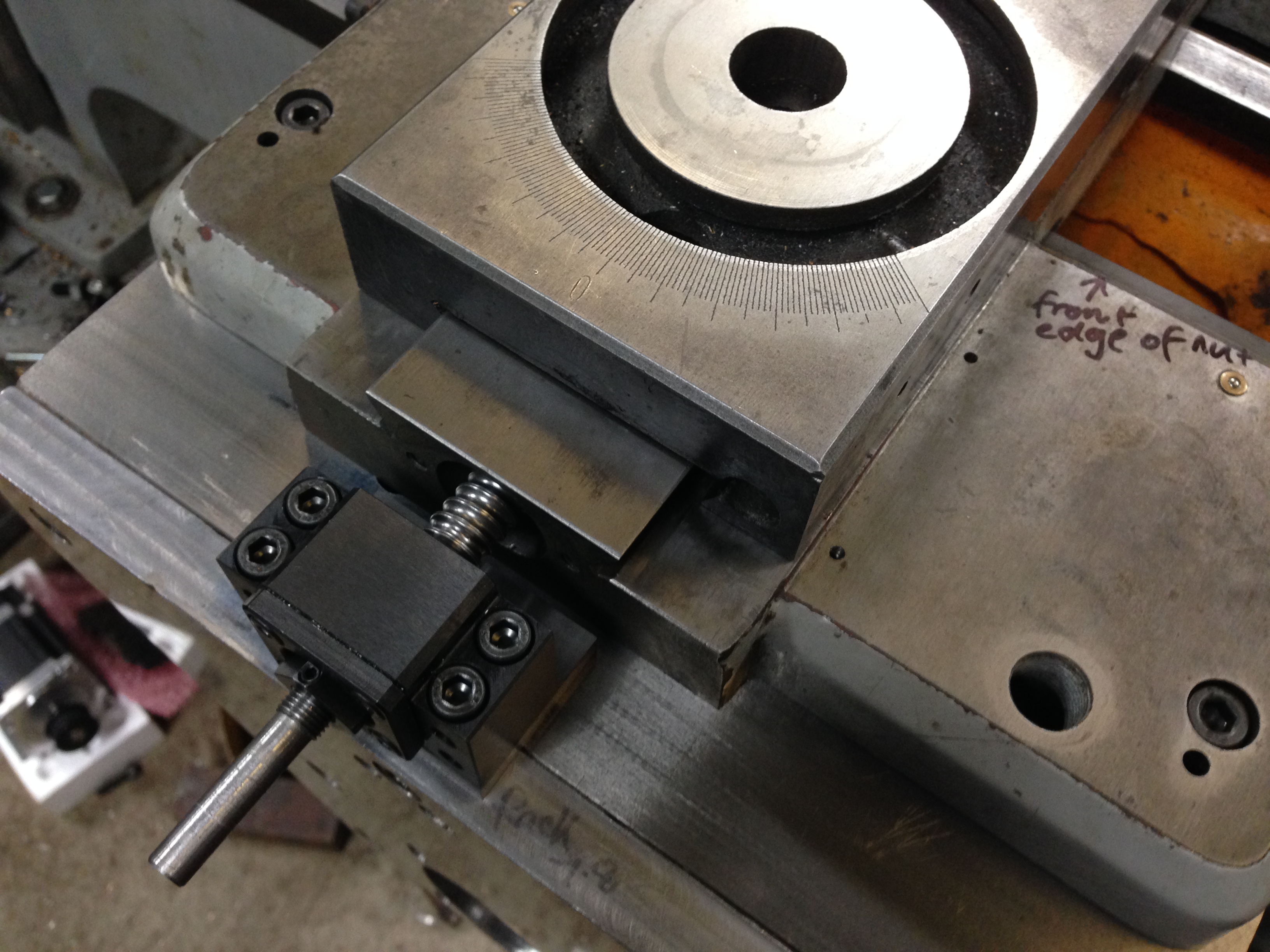
That thread is 3mm dia. The hole above the nut is the oil way, 1.5mm dia. Very tricky and too anxiety provoking to be thinking about a video. Amazingly, it all went well! I now have 2 oil holes for each of the 3 big ends. I will need to fill the well with oil with a medical syringe and fine needle, but.
The crankshaft, turned from stainless steel a year or two ago, and the conrods. The big ends now with lubrication points.
And here are the major engine components, after partial disassembly.
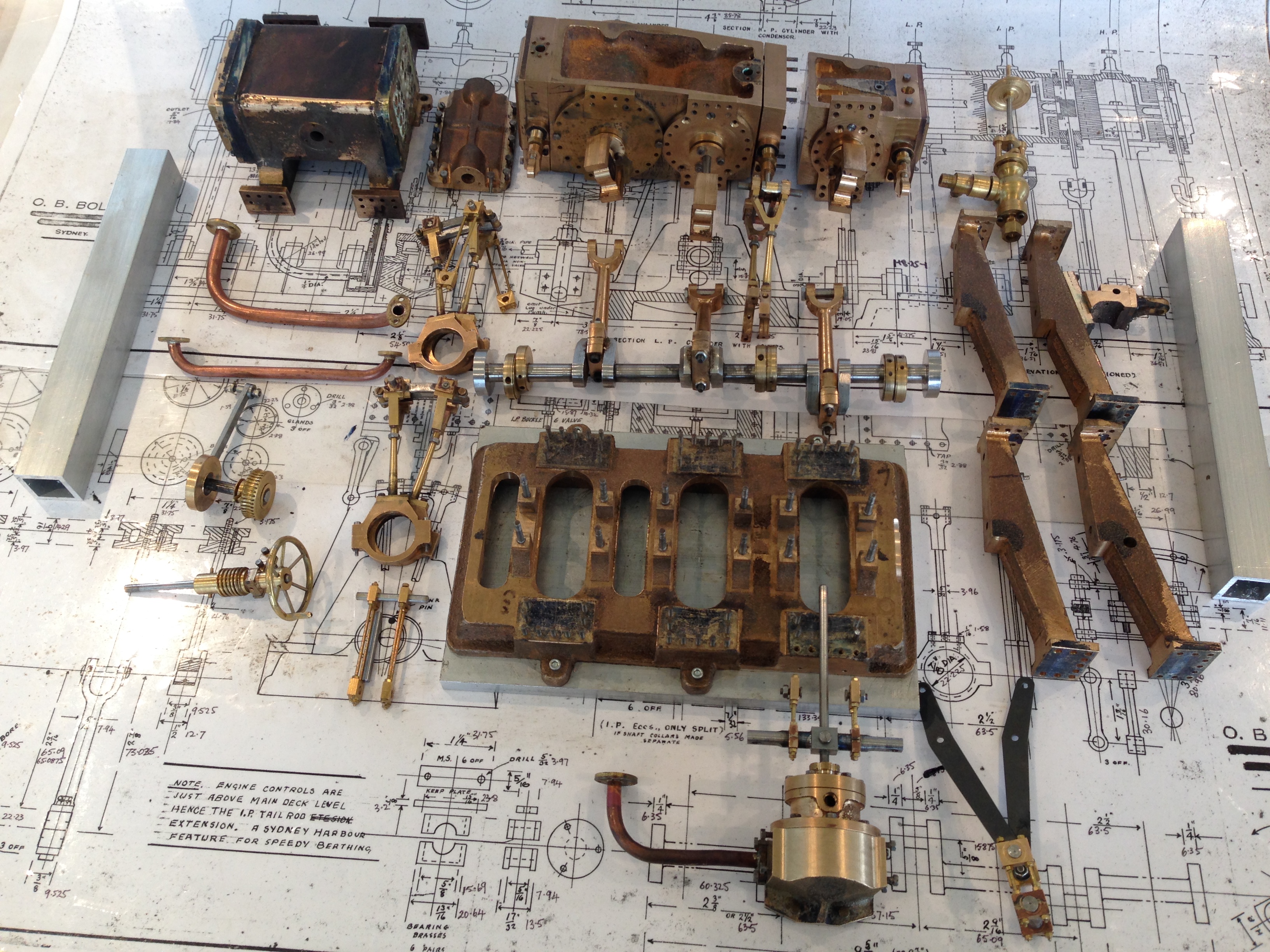
At top left is the condensor, then the cylinder block in 2 parts, then the steam supply valve. The square section tube is going to become the base. And so on. You get the picture. I will count the bits at some stage.
Then I cut and drilled the square section aluminium tube for the base.
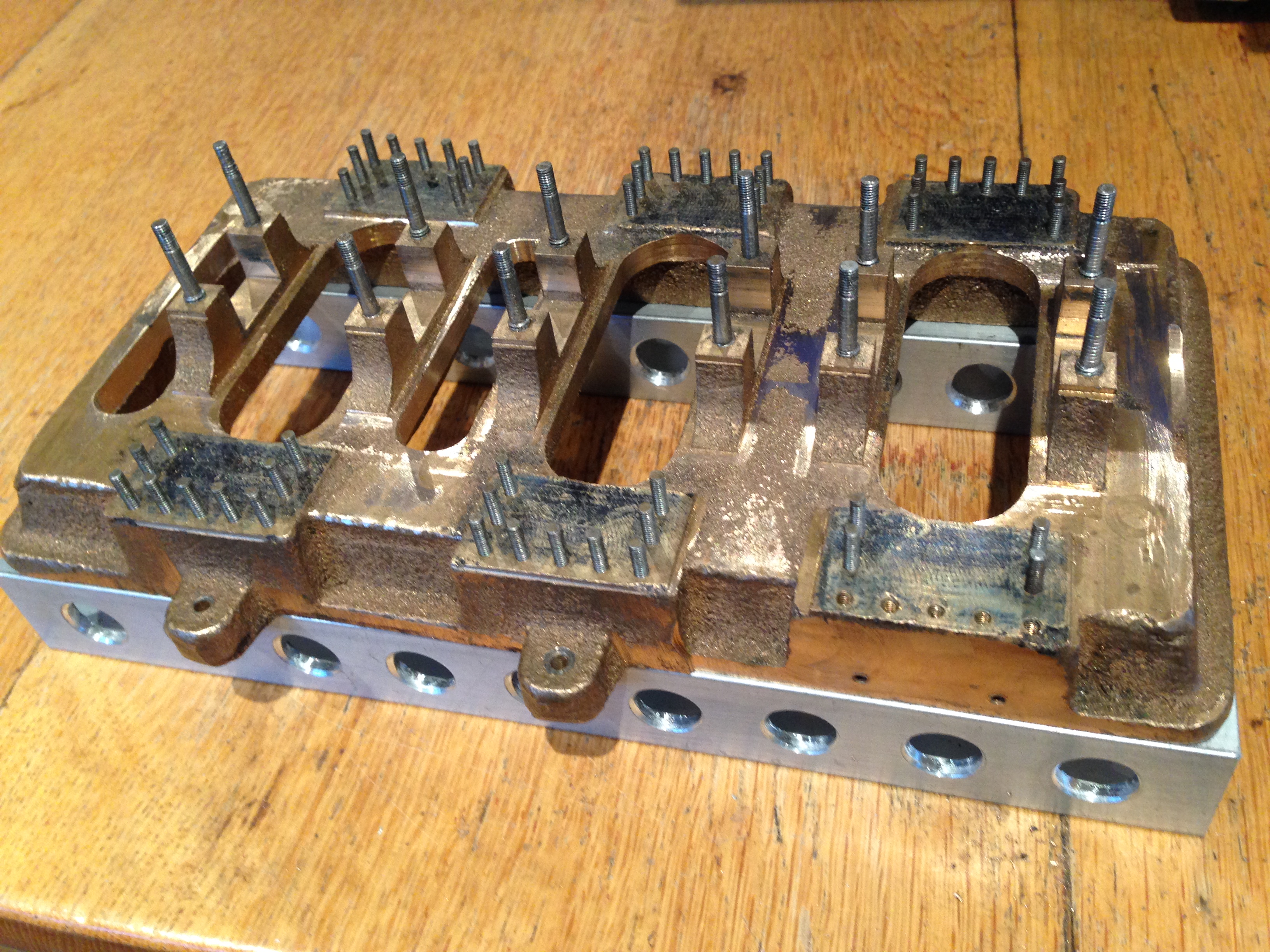
The cast base of the triple, with main bearing studs and column studs in place. All sitting on the square section alu. Have not decided whether to bolt it together, or just Loctite it.
Those holes in the square section were drilled and chamfered on the CNC mill.
April 3, 2017
Project in the Wings.
While finishing the triple expansion steam engine, I have decided on my next project. Actually, based on my past history of procrastination with the triple, I might even put aside the triple to start on this one.
Reading this article in “Model Engineers’ Workshop” gave me the inspiration to convert a rotary table to electronic control.

Dec 2016 MEW article
So I have commenced accumulating the bits and pieces…
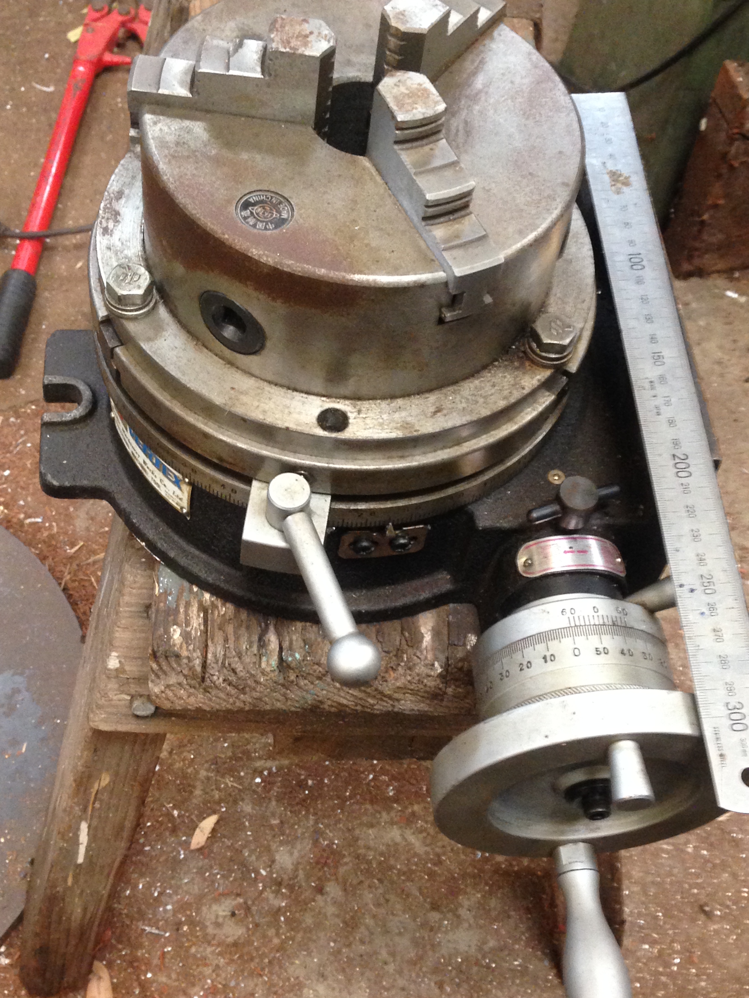
An 8″ Vertex rotary table. I have had this for years, but unused since acquiring a universal dividing head. Should be ideal for this project.
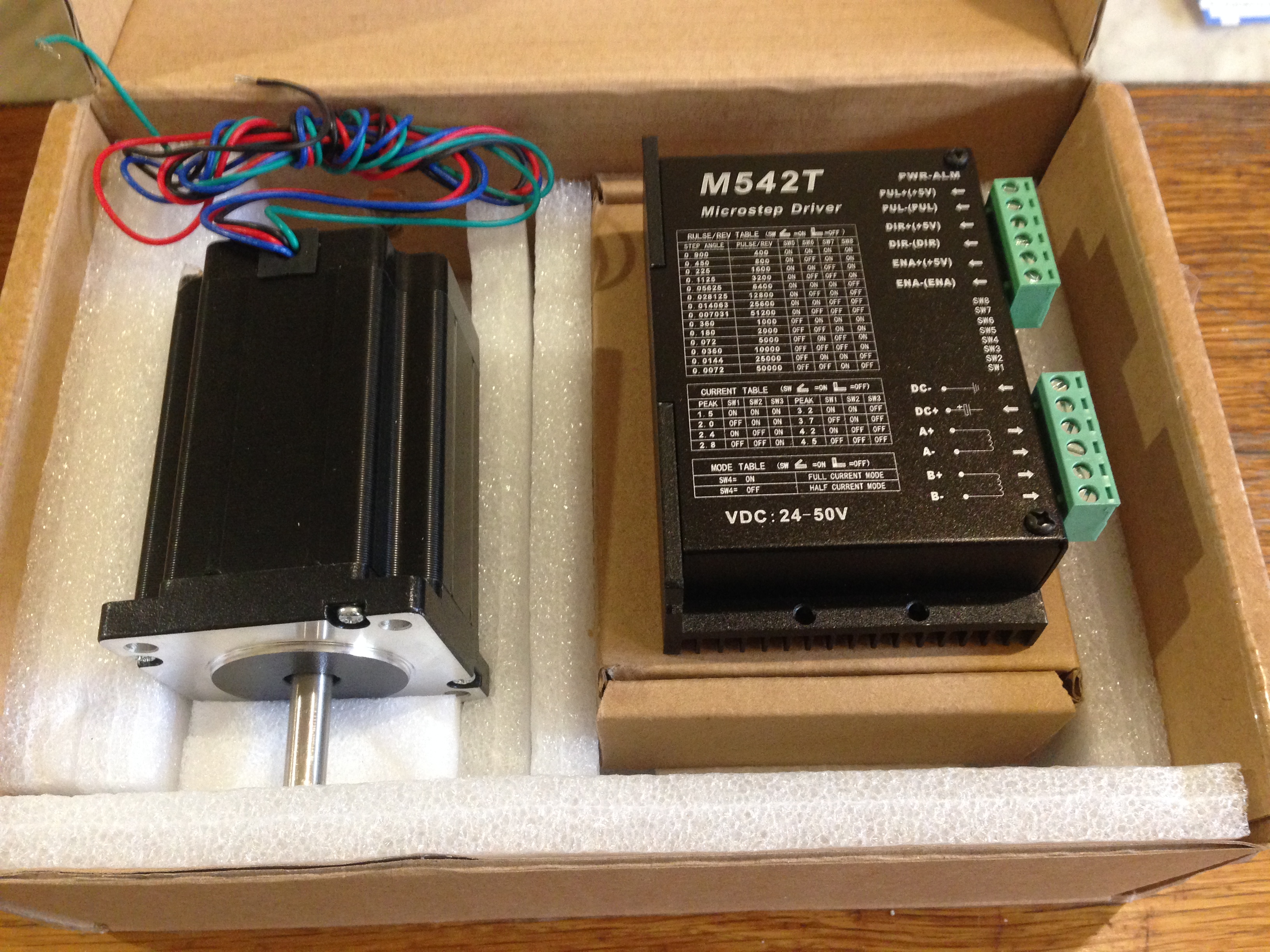
A Nema 24 Stepper motor, shafts at each end, so I can use the table manually as well as electronically. The Microstep driver was supplied packaged with the motor as a kit. $90AUD inc postage.

From the same supplier, a 48volt power supply. $38AUD

The brain of the system. A programable microcontroller “Arduino Uno”. I bought 5 of these for $20AUD post included.

And an easily attachable display. To attach the Arduino. $19AUD

And since I knew nothing about Arduinos, a “Getting Started” book. Excellent. On loan from a friend (thanks Stuart)

And to practice some circuits and get some idea about the Arduino programming, a starter kit of bits and pieces. $75AUD, but has been very instructive and loads of fun. The program to run the Arduino is downloadable free from the Internet, so this kit might be a bit superfluous.
And some items of kit. Each under $20AUD.
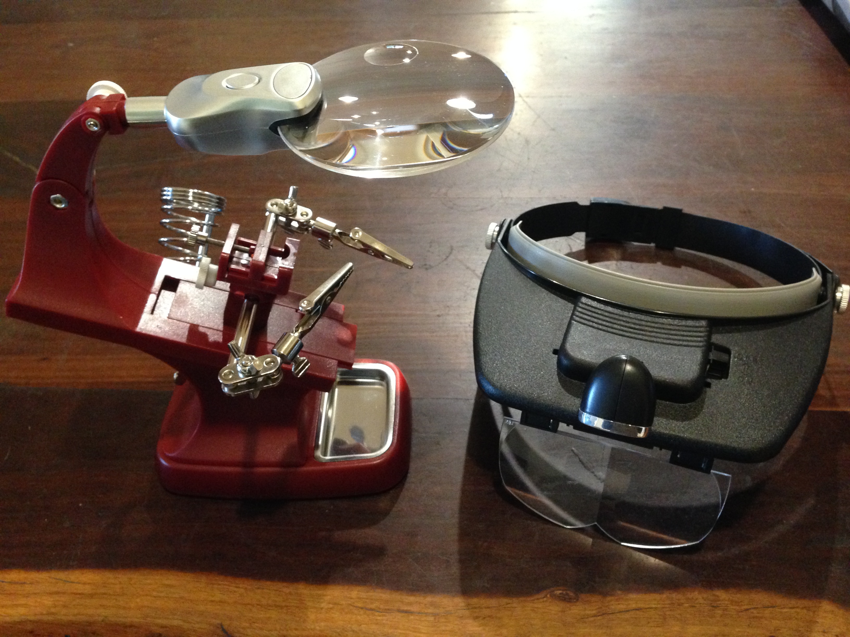
A magnifier soldering station, and head light and magnifier

A very cheap multimeter. Previous purchase. Works fine. $10AUD
I have disassembled the rotary table, and ordered a 12/8mm coupler. I am waiting for the coupler before I start designing and cutting the main part to be fabricated which is the piece which joins the stepper and the table.
Also ordered a box to contain the electronics and switches. Havn’t yet thought about cables, joiners etc.
April 2, 2017
Edwards Pump for the Triple Expansion Steam Engine
The triple expansion steam engine has been progressing, again. I started this project over 2 years ago, but I have taken many breaks, some prolongued. One break lasted over 6 months while I made some cannons.
I cannot remember when I made the Edwards pump for the triple, but it must be over a year ago. In the past few days I have returned to it, finalising the mounting to the engine, and joining the driving levers to the pump and the engine.
The Edwards pump creates the vacuum in the condenser chest. It is an air pump.
Attached to the Edwards pump are 2 water pumps, which return condensed steam as water, to the boiler. At least that is what I understand from the descriptions. It feels a bit odd, making these components before understanding what they really do.
The Edwards pump is the central cylinder and rod. The water pumps, bolted to the sides, are just lumps of semi machined cast gunmetal at the stage this photo was taken.
The step before the above picture, where the base of one water pump is machined.
The Edwards pump, and the 2 water pumps, almost finished, attached to the engine.
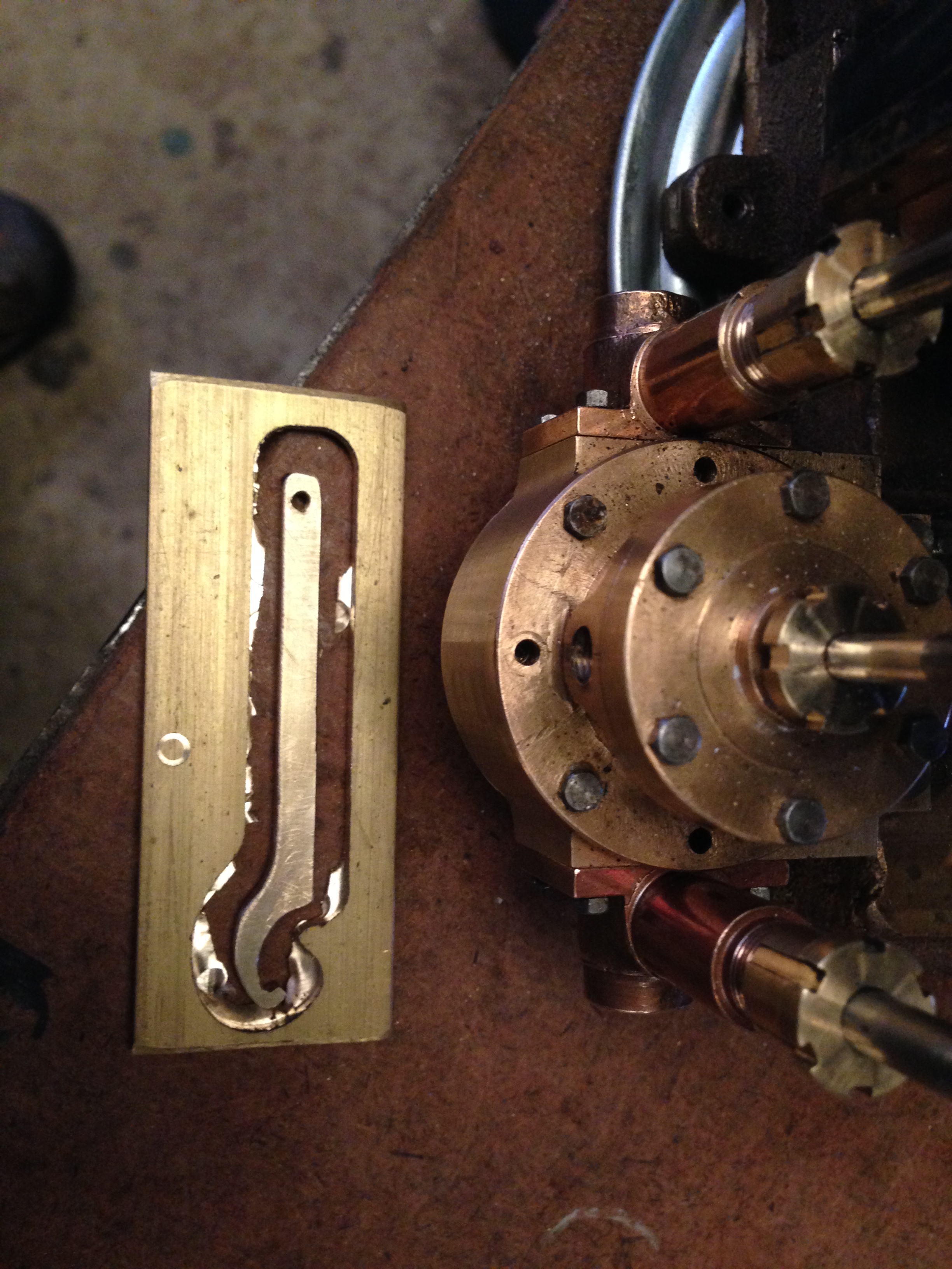
There is no clearance between the pump gland and the condensor, so the intitial hexagonal glands which I made (not shown) were unuseable. So I made these cylindrical glands which required a tiny hook spanner to tighten. The hook spanner was made on the CNC mill from 1/8″ brass plate. A little filing was required to shape the hooked tooth. Works nicely.
The pump unit, lower left, attached to the engine. Actuating levers driven off the low pressure cylinder (not yet connected).
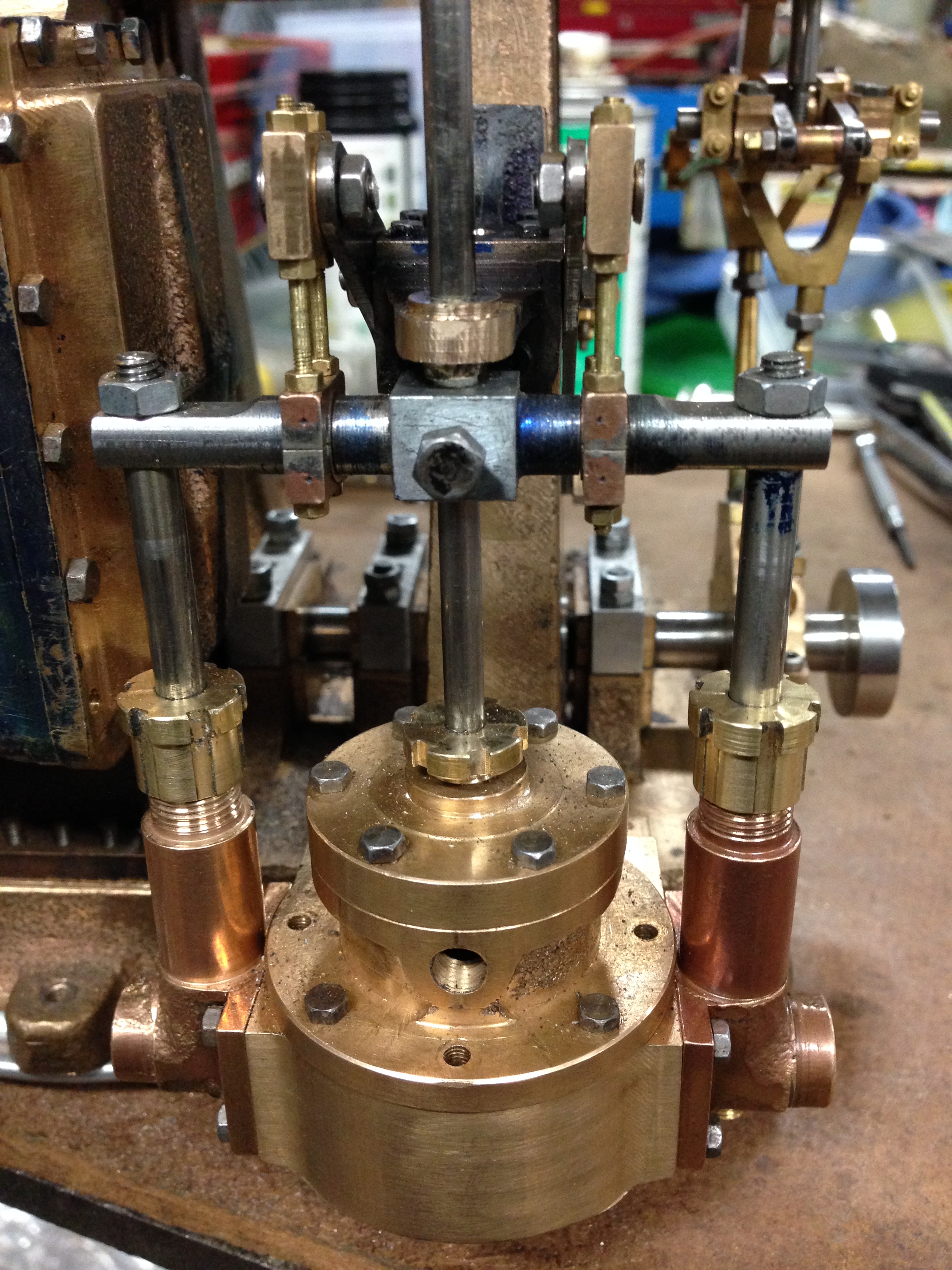
The pump unit viewed from the side.
So I am at the stage where I would like this project to be finished, so I can get on with other projects. It feels like it is close because there are very few castings remaining in the box. But I know that the entire engine has to be disassembled, and painstakingly reassembled, freeing up some of the tight parts so it will turn over more easily. Then the steam pipe hookups and valve timing. Then hopefully, a video of it running!
February 25, 2017
Swap Meet Bargains
Yesterday I travelled to Ballarat, (Victoria, Australia) to a swap meet which was held on 22 acres at the airfield.
Most of the stuff in the thousands of sites, was junk from shed and farm cleanouts. However, despite rapidly walking up and down the rows, I did not quite cover all of the sites. My Apple watch indicated that I had walked 18km (11.2 miles) and much of that was carrying a backpack full of bought items, so it was no wonder that my ankles were aching at the end of it.
I was really only interested in the few sites which had tools from factory closures. But my eye was drawn to the very old Caterpillar crawler tractor, a 2 tonner, not too derelict except for a broken exhaust manifold and some rusted growsers. $AUD9500, so I kept on walking. Lots of elderly, old and antique cars, motor bikes, and vehicular bits and pieces.
The following photos show most of the stuff which I bought, and some prices (except for the ones which SWMBO must never discover).
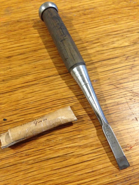
A Japanese woodworker’s chisel. 9 mm wide. Razer sharp, oak handle. I buy one of these at each Ballarat swap meet from the same seller, a lovely Japanese woodworker who lives and works in Victoria. These chisels are a pleasure to use. $AUD25

This was a bargain. A set of good quality English BA open ender spanners, probably unused, for $AUD8
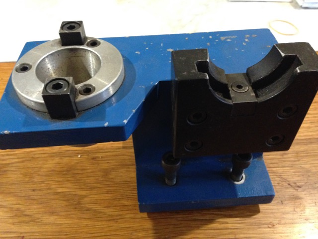
I dont know what this is called, but it has an INT40 taper, and bolts to the workbench or mill for inserting and removing cutters from the toolholholder, and avoiding the cutter dropping down and being damaged. Is it a tool setter? Anyway, $AUD40

Used but sharp, quality brands. Carbide ball nose end mill, countersink bit, T slot cutter, and 1/4″ BSP spiral tap. $AUD30
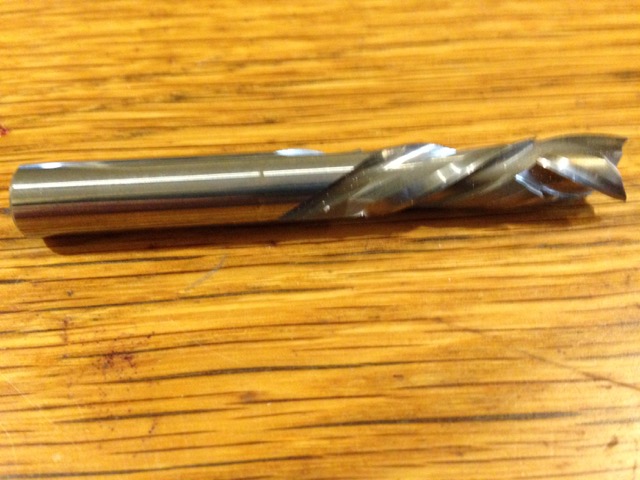
A new, interesting woodworking cutter, carbide, with left and right hand spirals to avoid surface furring. $AUD10
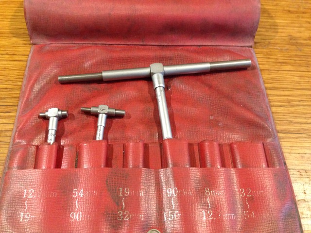
3 Mitutoyo telescoping gauges. $AUD10
I mulled over a Mitutoyo 1000mm vernier caliper in perfect condition for $AUD300, but decided that it was a wanted rather than needed item, and walked on.
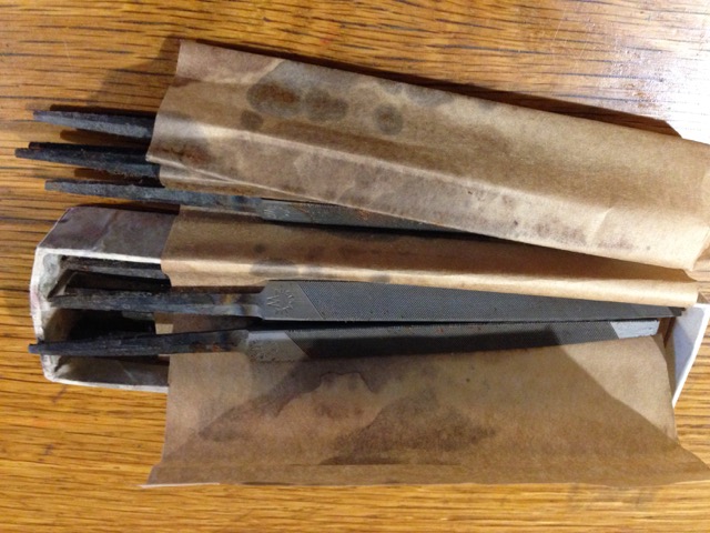
A box of 12 brand new quality Wiltshire triangular files. $AUD12
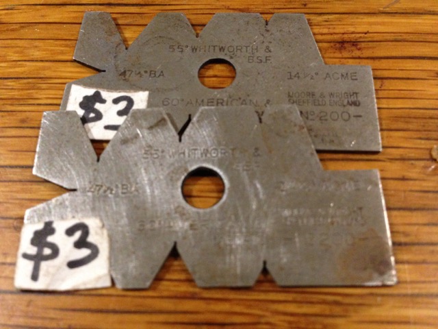
2 very nice Moore and Wright thread gauges, which have BA and Acme threads as well as metric and Imperial angles. $AUD6
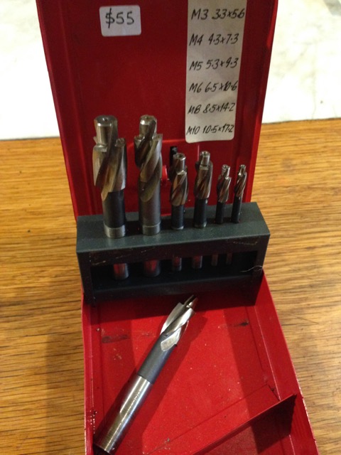
A box of metric counterbores. Not cheap, but good price considering the German quality, and condition. $AUD55
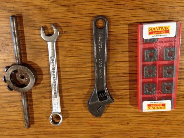
Small die holder, Sidchrome 10mm spanner, tiny Dowidatadjuster and new box of inserts. All useful. About $AUD45
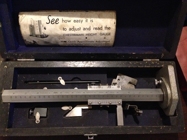
Chesterman vernier height gauge. Unusual triangular column. Beautiful condition, complete range of accessories, in a lined box. Metric and Imperial. Price not to be dislosed to SWMBO.
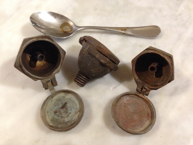
These are brass wick type oilers which I will give to the local Vintage Machinery Society. No markings.
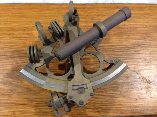
My brother was a navigator in the Australian Air Force many years ago, before the age of satellite navigation. He would sight the stars using a sextant something like this to calculate the plane’s position, while standing in a glass dome in the roof of the aircraft. (I think that I got that description approximately correct). He once told me that he would like to have a sextant again, so when I spotted this at the swap meet, and the price was OK, I decided to get it for him. Maybe it will make up for all of those forgotten birthdays. So little brother, leave some room in your suitcase when you next visit. I will leave the clean up and renovation to you.
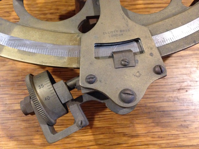
Elliott Bros London.
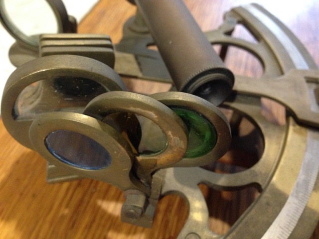
It looks fairly complete and intact. Of course I have no idea how it works.
October 7, 2016
Model Ottoman Bombard – Painting
I would have preferred that the title of this blog was “Finishing the Ottoman Bombard”, but I am still waiting for the vectors of the barrel mouth decorations and Arabic (?) writing, and the touch hole.
But I have at least painted the bombard, and the pictures follow. You will notice that I have not attempted to reproduce the bronze or copper colours of the orginal in Fort Nelson. Partly because I doubted my ability to make painting such variegated patterns realistic, and partly because the cannon would not have looked like that in its heyday of 1464. It would probably have been either black, like most SBML cannons (smooth bore muzzle loading), or possibly gaudy golds and reds and blues like other medieval items. So I painted it black. I like it. If I get evidence that it should be more colourful I can change it later.
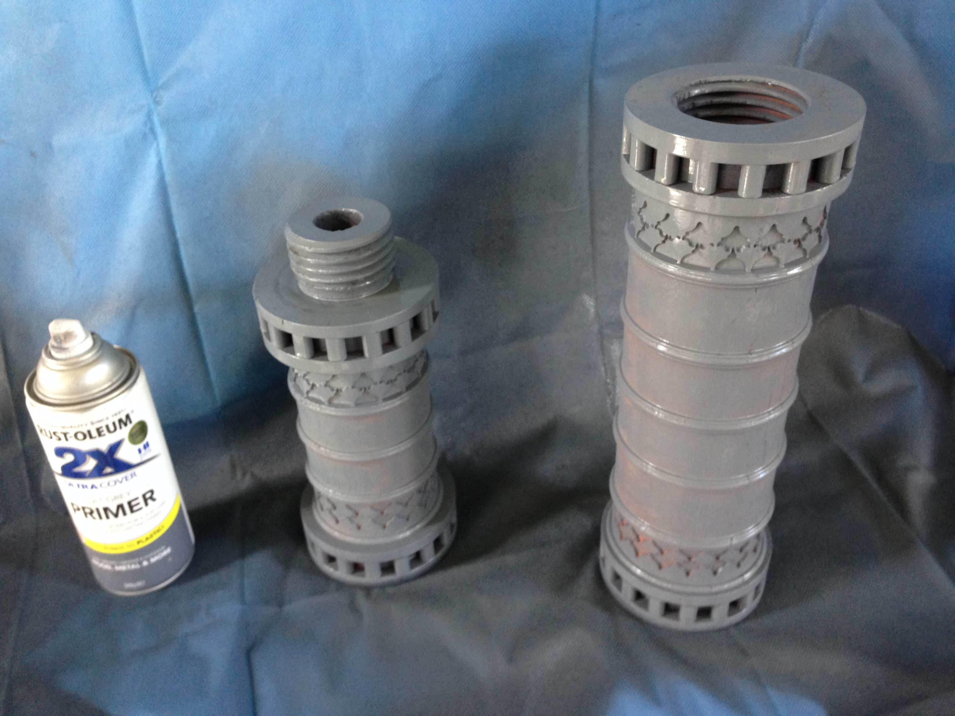
First coat – Primer. Hmmm… interesting colour.
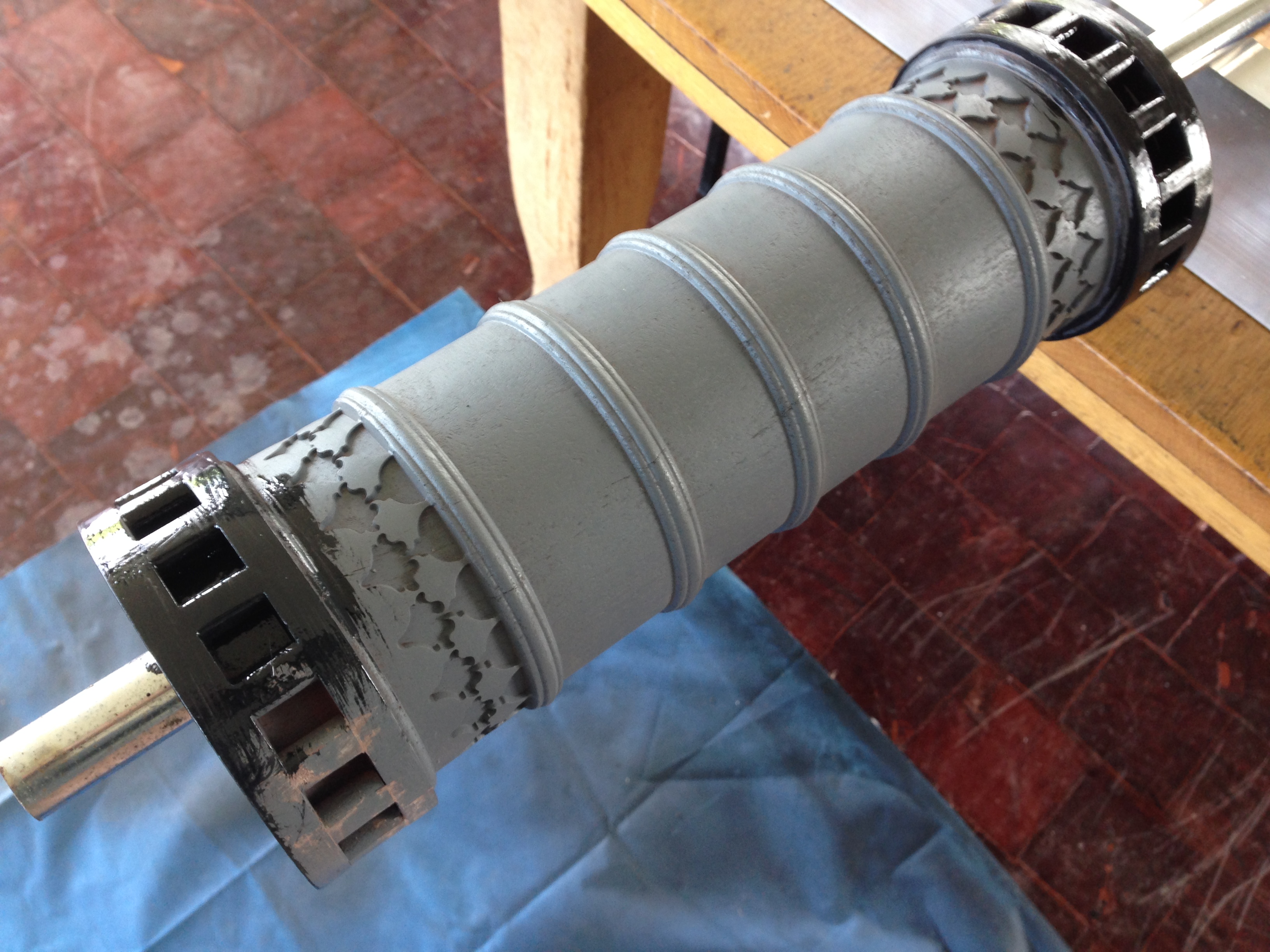
Next coat – matt black brushed on, to fill the hairline wood cracks. Incidentally, the (dirty) parquetry floor is also made from the red gum house stumps from which the cannon is made.
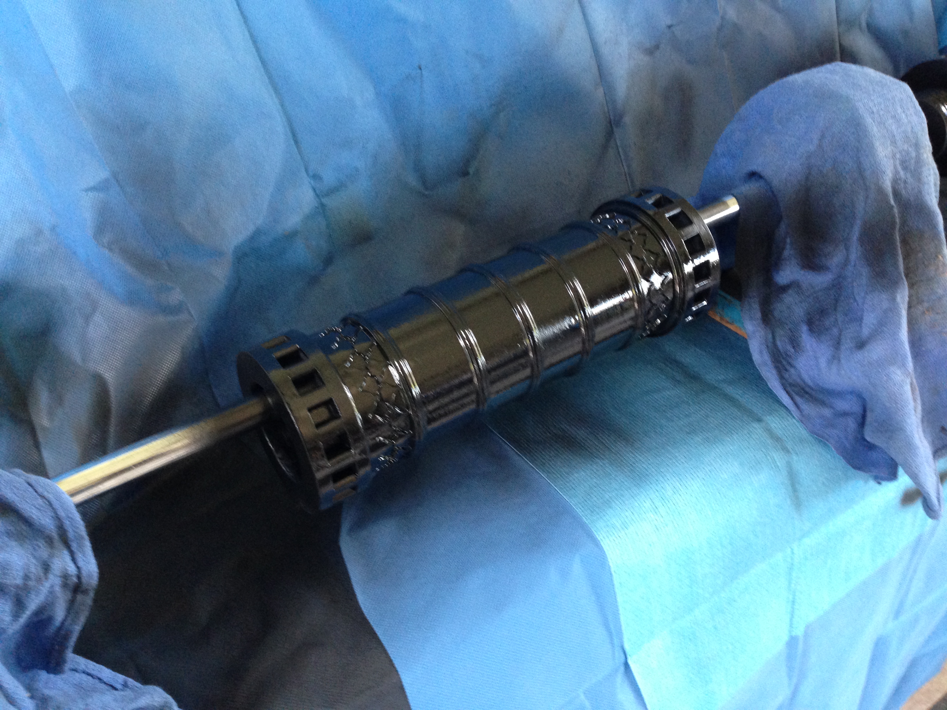
final two coats – matt black, from a spray can.
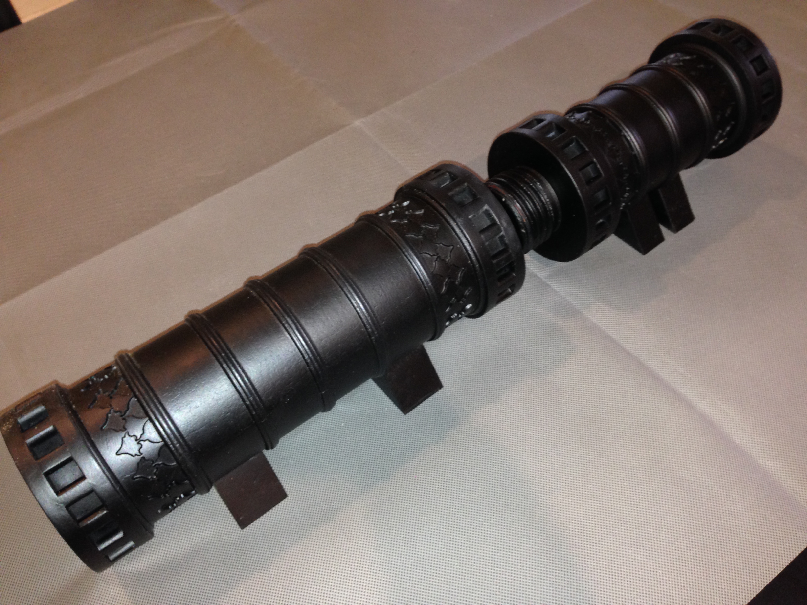
So there it is, finished except for the barrel mouth engraving, and the touch hole. Now what to do with it… SWMBO says it might be useful as an umbrella stand.
The breech. 25mm diameter explosion chamber. 1:10 scale
The barrel, 63mm bore.
Assembled. The model is 520mm long.
It does need some decoration
September 28, 2016
Modelling A Turkish Bombard- The Pins
There are 16 pins at each end of each section of the cannon.
These were certainly used as leverage points, for very strong men with large levers to rotate the 8-9 tonne segments against each other to engage and tighten the screw.
I cannot see how the pins would have been cast with the breech and barrel. For my model I decided to make separate pins and fit them into the gap between the big rings, then insert a grub screw through both rings and the pin. The holes are then filled.
I wonder if a similar method was used in 1464. I would love to have a close look at the original cannon to figure this out. From the photographs, I can see no evidence of later insertion of pins, but neither can I see how it would have been done any other way.
Drilling the holes for the grub screws
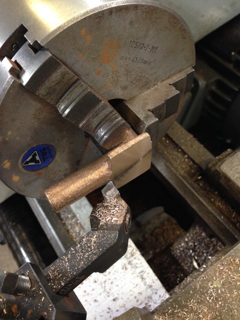
In order to continue with red gum, I made my own pins. This is the setup. The blank is held approximately centre in a 4 jaw….
…and the pins are turned, centre drilled, drilled, cut to length, and tapped M4. 64 altogether.
The M4 x 25mm grubscrew is screwed into the pin. The wood join is super glued. Also, I am attempting to patch the worst of the thread tearouts.
Using a battery screwdriver to insert the grub screws. The pins protrude above the ring surface for a reason..
Sanding the pins flush with the rings. Check the photo of the original 1464 model. There is also some wood filler in other splits. Not surprising after holding up a house for 70 years.
The holes are now filled with wood filler, and will be sanded flush. They should be invisible after painting.
Next the painting, the stands, and some cannon balls. How to reproduce that aged copper colour…
September 13, 2016
Turkish Bombard 1:10 scale
Just for fun I will use my newly converted CNC lathe to make a 1:10 bombard. The original was cast in 1464 and was thought to be a close copy of the bombards which Mehmet 2 (“the conqueror”) used to breach the walls of Constantinople in 1453. There are several of these bombards still in existence, including one in UK, which was given to Queen Victoria by the then Turkish Sultan.
These bombards were last used, against the British, in 1807, when a British warship was holed with substantial loss of life. Pretty amazing for a 340 year old weapon.
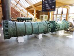
5.2 meters long, 1.060 meter diameter. 16.8 tonnes.
The large thread connected the halves. Easier transportation, and casting.
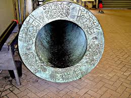
Is this Turkish or Arabic?
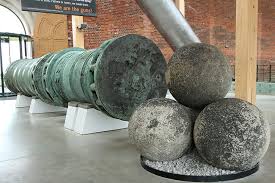
Granite balls are 630mm diameter.

A reconstruction of the walls of Constantinople, with moat. Almost 1000 years old in 1453

And as they are today. Massive. High.
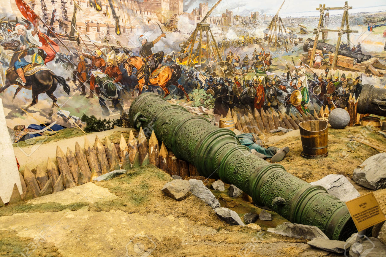
Huge siege cannon used in the final assault and fall of Constantinople in 1453. Diorama in Askeri Museum, Istanbul, Turkey. The bombards were probably dug in, to manage the massive recoil, and concentrate the aim at a particular wall section. There is a wooden structure built around the cannon in the background of this modern picture. As far as I know there are no surviving wooden structures like this. Nor have I come across any old pictures, but if anyone knows of any I would be very interested. The bombards took about 3 hours to cool, cleanout and reload.
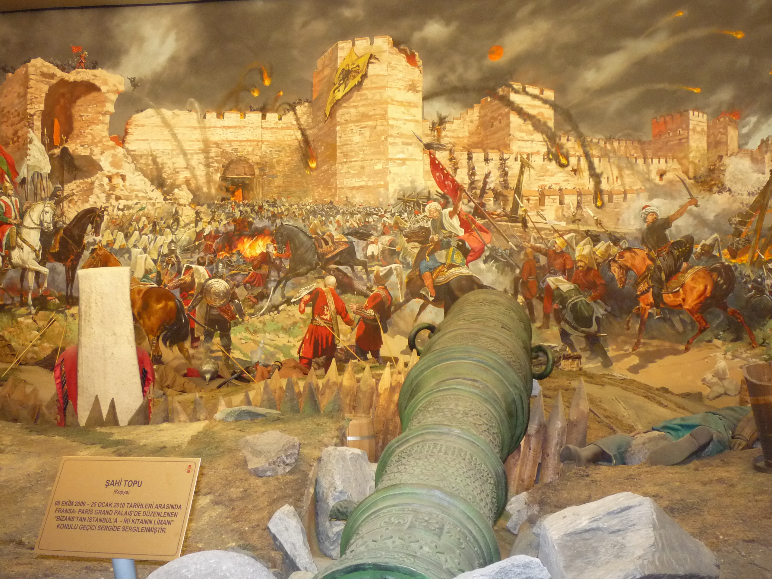
My model will be about 520mm long. I would like to make it from bronze, or gunmetal as in the original. Any mistakes will be costly.
So I have decided to make a prototype in wood. That will test my drawing, the machining procedure, and the final appearance. Not to mention how the CNC lathe will handle the task.
I will use a very dense, tight grained Australian hardwood (red gum). The wood was salvaged when my house stumps were replaced with concrete. Some was used to make parquetry, and the rest was put aside for possible future use. Such as this.
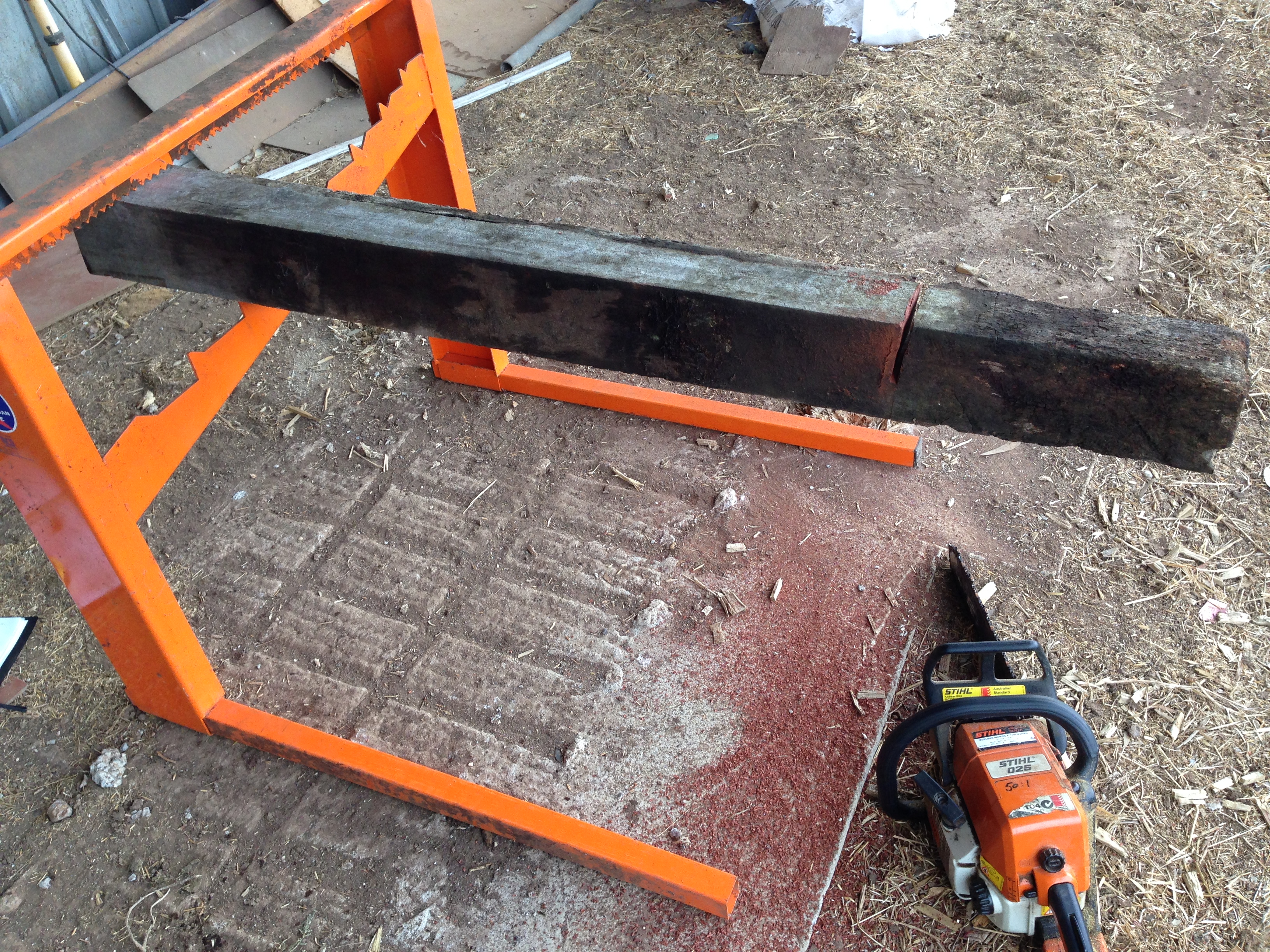
About to cut off the below ground section of a 70 year old house stump.
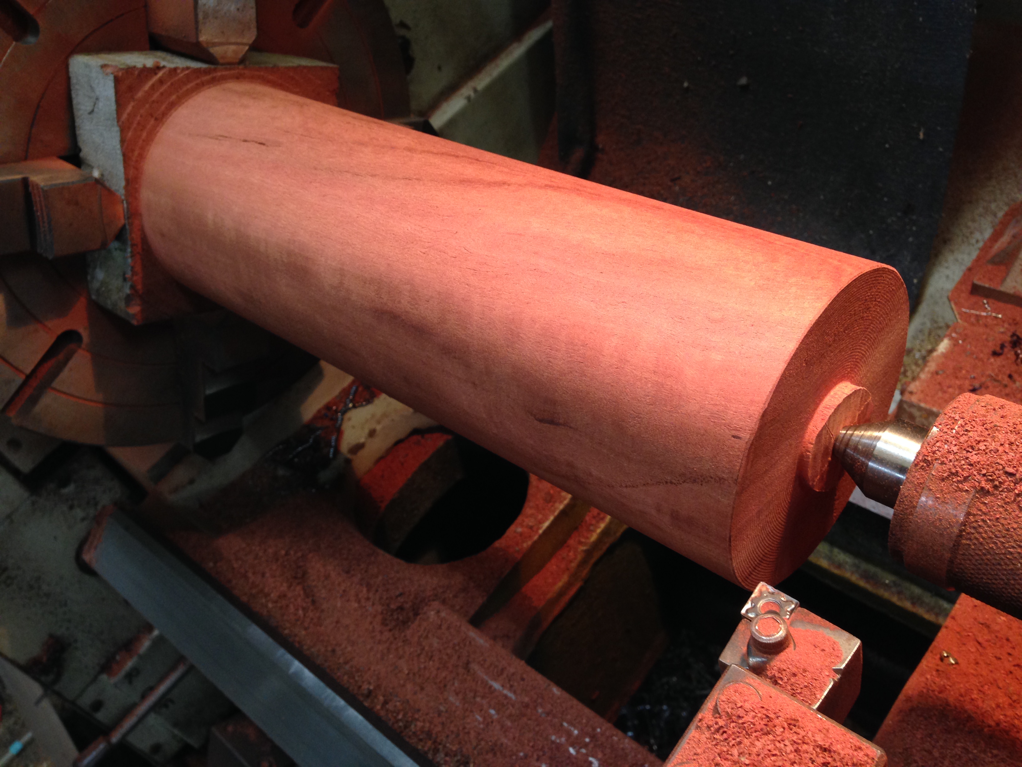
A 5hp metal lathe with a tungsten bit chomps through the hard dry wood.
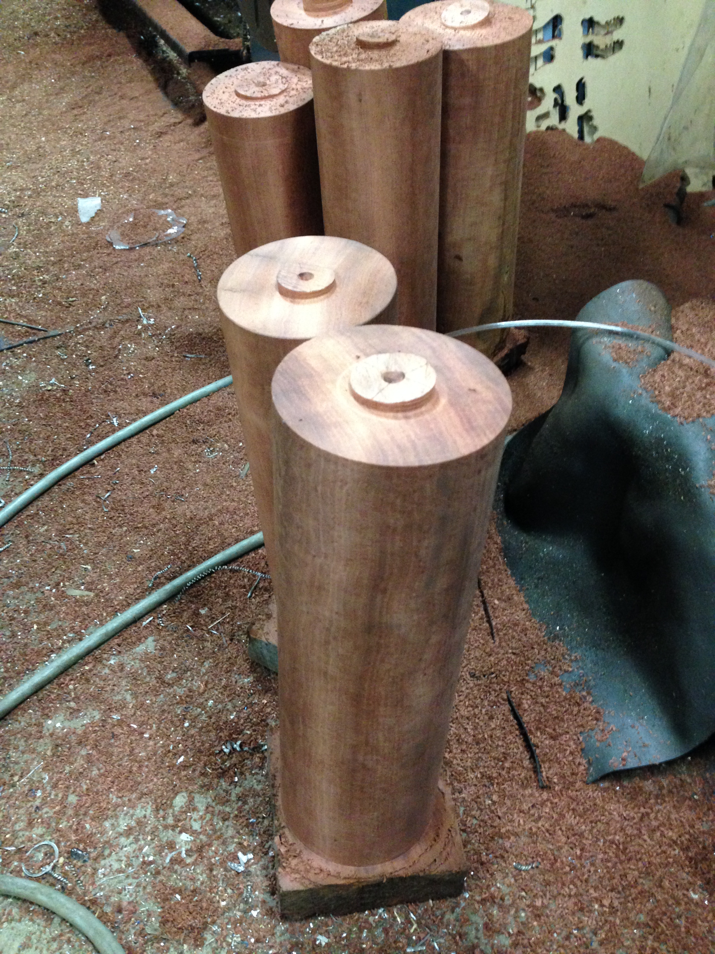
I turned 6 lengths before I found 2 that were satisfactory. The rest had sap holes or splits.
I have used Ezilathe to generate the G codes.
to be continued….
September 6, 2016
CNC Lathe Conversion- final
Before I am hung, drawn and quartered, for operating a lathe without guards, here is the proof that I have been sensible.
Guard over the X axis pulleys. I like to watch the wheels going round and round, hence the transparent top. Also note the cover over the exposed ball screw.
Cover over the Z axis pulleys and belt, again transparent. If I wore a watch it would be transparent.
I also installed an ER40 collet chuck. I will be using this for all work with diameters under 26mm.
August 31, 2016
Steam Engine Oilers
Knowing that I have an interest in CNC machining, Tom, from the Vintage Machinery Club in Geelong asked me to make a pair of oilers for a very old Wedlake and Dendy steam engine. The engine is a large (to me anyway) stationary engine, which is run on steam several times each year. The oilers for the cross slides were missing.
We searched the Internet for pictures of W&D steam engines, but could find no pictures or diagrams of the oilers. So Tom sketched a design, and I drew a CAD diagram. The dimensions were finally determined by the materials which I had available… some 1.5″ brass rod and some 1.5″ copper tube.
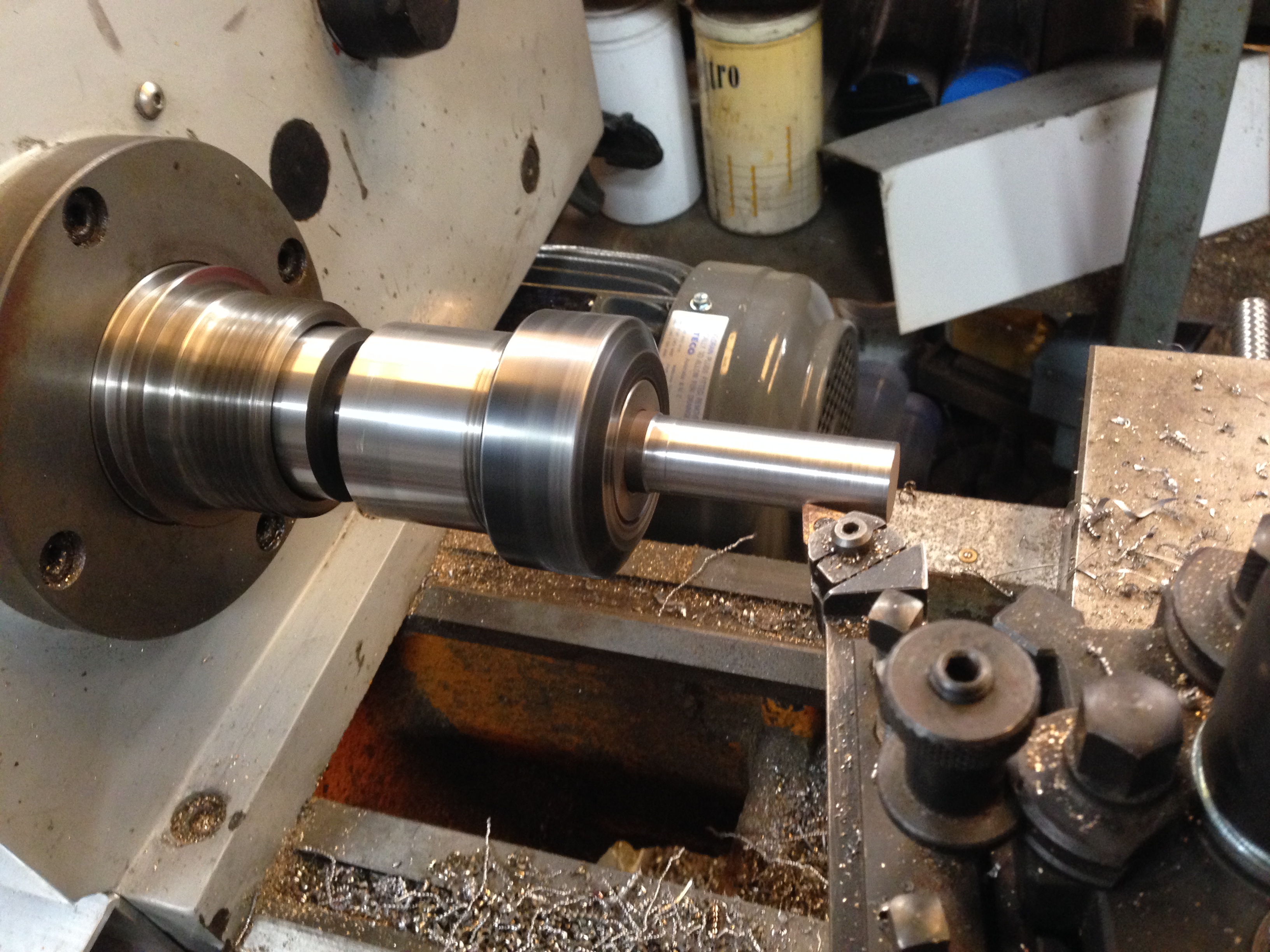
This is the almost finished product.
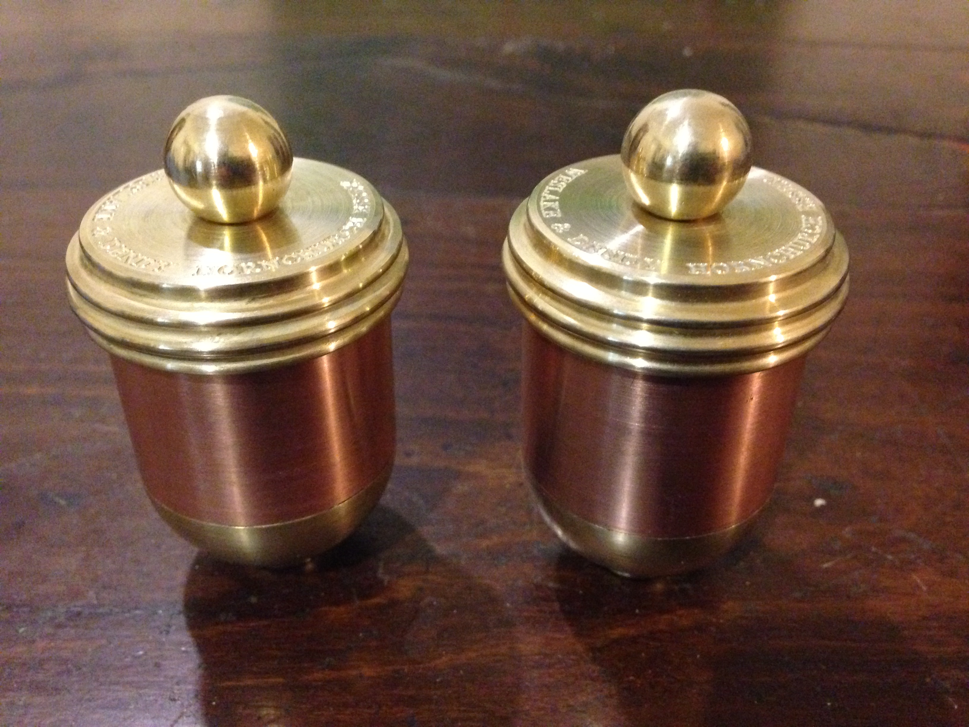
Just needs 1/4″ BSPT fittings and and oil wick tube so they can be fitted to the engine.
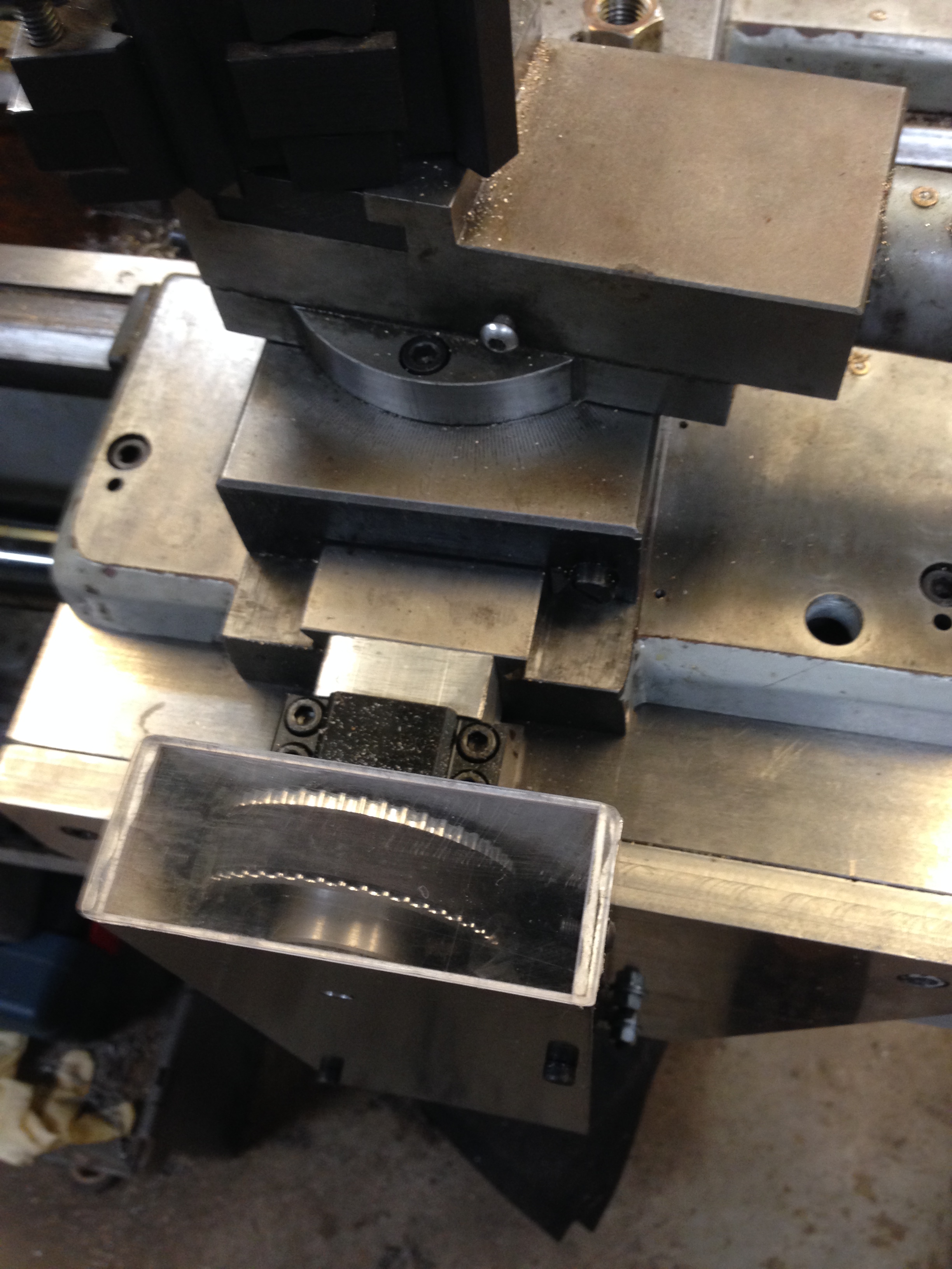
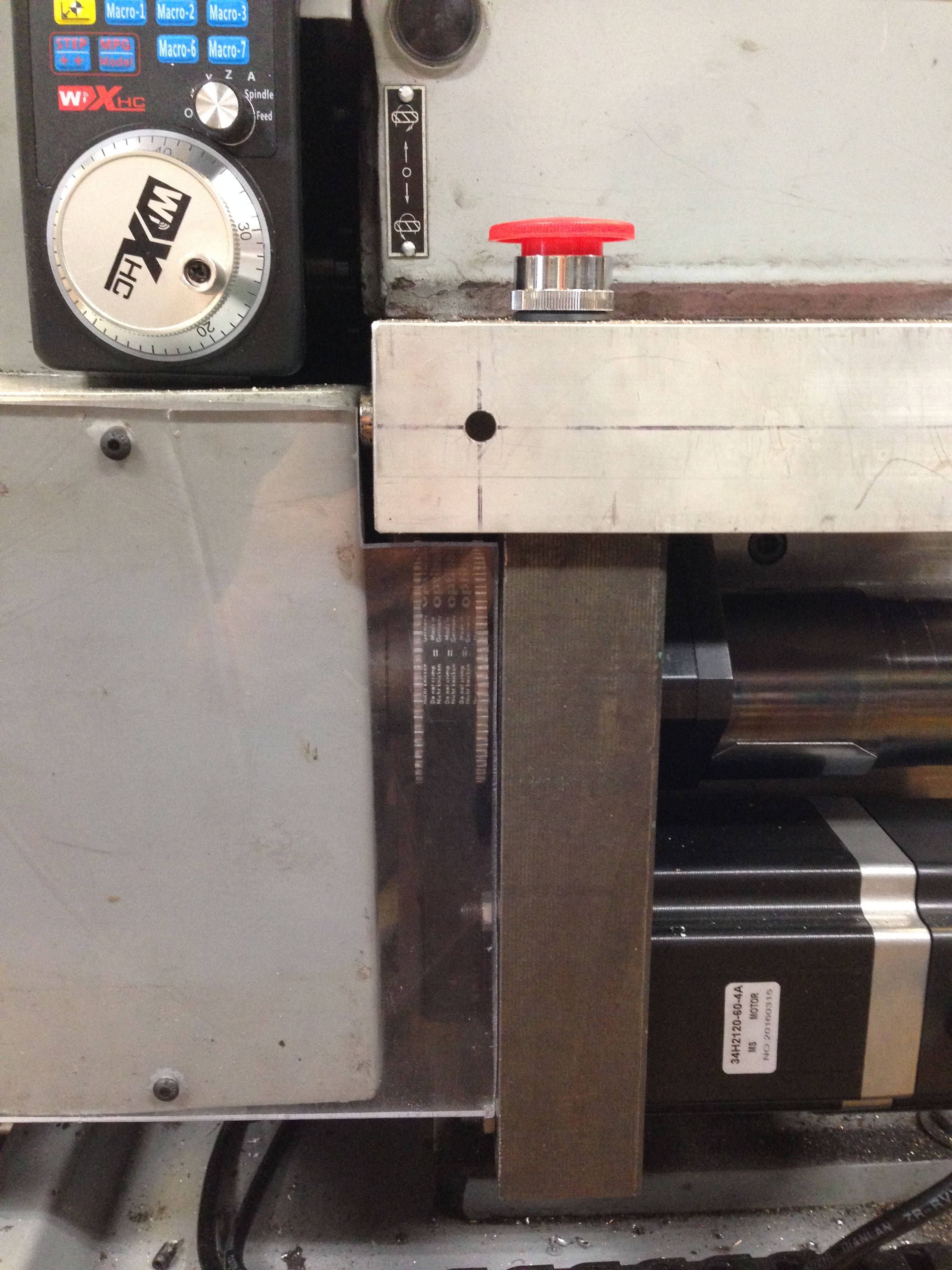
The copper tube silver soldered to the brass cylinders (top), the brass blanks for the lids (bottom) and the mandrel to hold the assembly (bottom centre) during CNC turning and drilling.
The mandrel to hold the body (left) and the mandrel for the lid (right). The cap screw head and hole in the mandrel have a 2 degree taper. The slits were cut with a 1mm thick friction blade.
Rough turning the base.
Turning the lid. The mandrel is held in an ER32 collet chuck
Engraving the lid. Using a mister for cooling and lubrication. 16000rpm, 200mm/min, 90 degree TC engraving cutter.
The oilers work by wicking the oil from the reservoir into a tube which drains through the base onto the engine slide. When the wick tubes are fitted the oilers can be fitted to the engine.
The 1865 Wedlake and Dendy
1865
My lathe is a Boxford TCL125, using Mach3. The G code is generated using Ezilathe.
Below is a link to an oil cup from “USS Monitor”, of American civil war fame. One of the first ironclads, powered only by steam.
http://www.marinersmuseum.org/blog/2010/04/one-oil-cup-down/
(ps. The lathe which I was converting to CNC was the subject of previous posts and is now working, but needs some guards fitted and a bit of fine tuning.)
August 29, 2016
OK, so guess the purpose
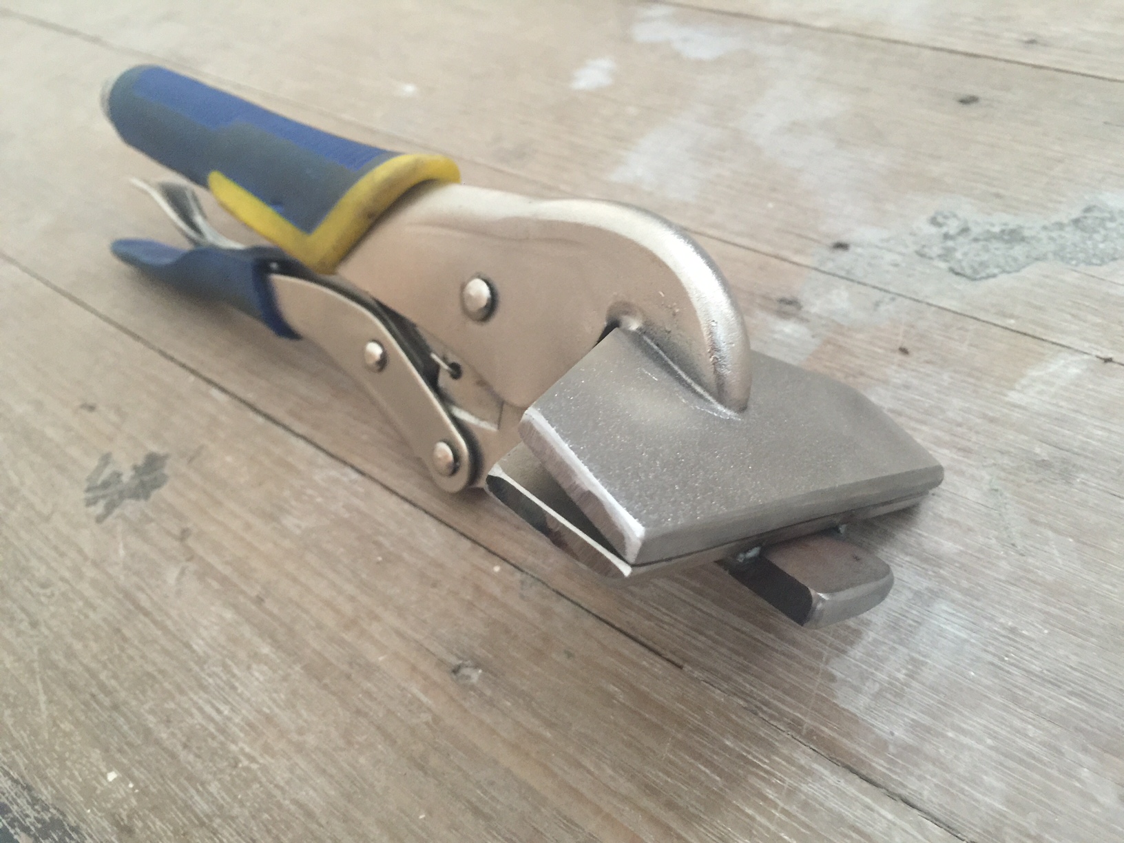
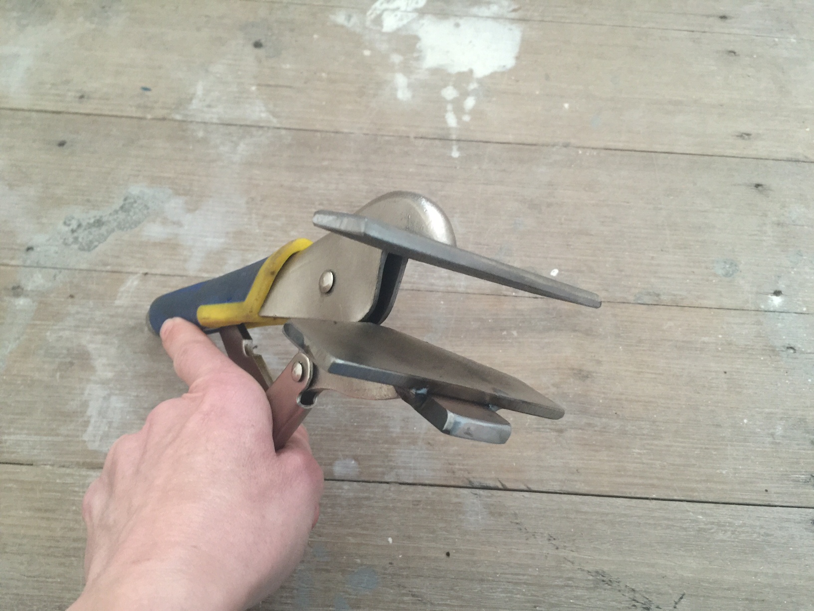
A pair of sheet metal pliers, to which I welded a steel tab. Why?
For the answer click on the link.
For some reason the auto link is not working. You will have to type the link manually.
Later update… I dont get this. Even the manually typed link to the explanation does not appear.
OK. The explanation is that these sheet metal pliers have been converted into canvas stretching pliers for my daughter who likes to make her own canvases for oil painting. Youtube sucks sometimes.
Try searching “Thomas Baker’s canvas stretching tutorial” to see how the pliers are used.
August 13, 2016
MORE ANCIENT GREEK TECHNOLOGY, THE ANTIKYTHERA MECHANISM
This mechanism was discovered in 1901, in a Roman era shipwreck, off the Greek island of Antikythera, which is a bit north of Crete.
It has been dated to between 100BCE and 205BCE, with the older date considered the best estimate. ie, about 2200 years old. Experts believe that its makers were Greek.
It is currently housed in the Greek National Archeological Museum in Athens.
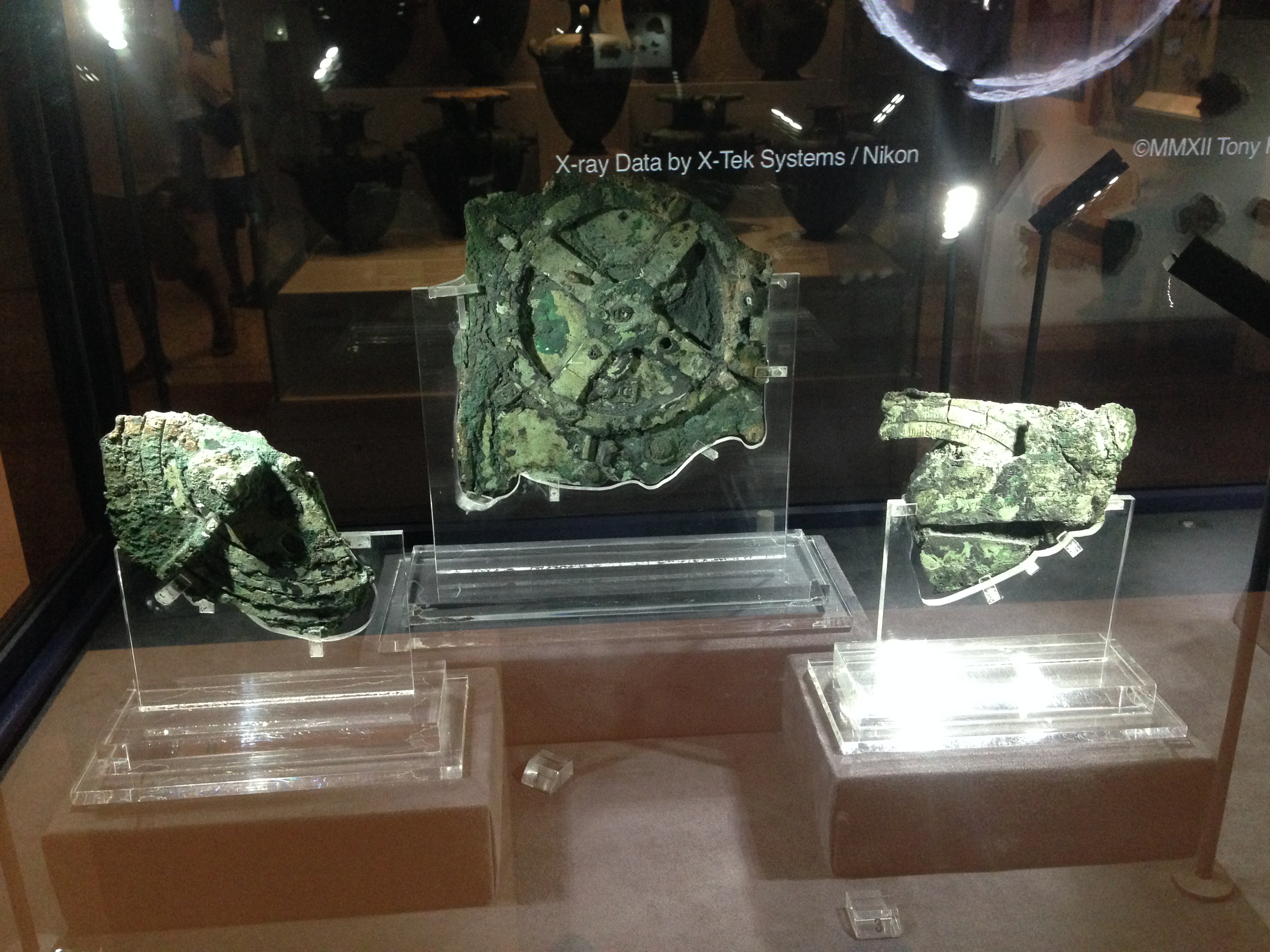
Not much at first glance, but when it was examined with modern scanning and X ray techniques…
Look it up on Wikipedia..
https://en.wikipedia.org/wiki/Antikythera_mechanism
According to the Wikipedia entry the gear teeth are too irregular to have been machine cut,
but watch the computer reconstruction. Could you make this machine without a lathe and gear cutters?
How much more technology did the ancients have that has not survived the ravages of time? A lathe for example.
August 12, 2016
ANCIENT GREEK MACHINING
I recently had a light globe switched on in my brain.
I was holidaying in Athens (the one in Greece), and was gobsmacked by the huge, fabulous collection of statues, mosaics, ceramics, gold jewellery and masks, bronze and iron weapons in the National Archeological Museum. I took many photos, and might post some in later blogs.
Three items sent shivers down my spine.
- The gold death mask of Agamemnon (probably not Agamemnon’s but that is another story).
- The Antikythera machine. More about that in a future post.
- A gynaecological speculum.
There was a display with many surgical instruments. These have been found at various archeological digs in Greece, and while not precisely dated (at least not labelled) they are mostly from 500-200 BCE.
My eye was immediately drawn to an instrument which looked very familiar. I was a gynaecologist in my previous life, and this could have come from my instruments. (except that the dark bronze surface might not have been acceptable to patients).

Not a great photo, through a glass cover, and ISO cranked up to several thousand.
The instrument is labelled a vaginal dilator, but I am quite certain that it is a vaginal speculum. A speculum is used to inspect the vaginal walls and uterine cervix. (That might be too much information my metal working/ engine making/ machinery minded readers. If so, too bad.)
It is said to be made of bronze. The Ancient Greeks were highly skilled at metal casting, as evidenced by the many complex and beautiful bronze statues and weapons and implements on display.
It interested me for several reasons. Bear in mind that not many archeology museum visitors are gynaecologists who know about making threads in metal.
It looks quite functional, and if cleaned up, given a shiny surface and sterilized it could be used today.
The threaded section is very regular and smooth. I would loved to have taken some measurements of the thread with a micrometer, but had to be content with a prolonged inspection through the glass case. The thread appears to me to be so regular, that it could not have been hand filed. It must have been machine made. I have seen hand made threads on medieval machines, and they are crude compared with this one.
Either this is not an ancient Greek instrument but a more modern instrument accidentally included in the display (pretty unlikely, considering the professionalism of the people involved). (ps. If you Google Pompeii speculum, you will see that similar instruments have been unearthed at Pompeii… buried since 79ce.)
Or….. the ancient Greeks had screw cutting lathes.
Ridiculous you say?
Wait until my next post about the Antikythera machine. If if you just cannot wait, look it up. It is mind blowing.
July 20, 2016
CNC Lathe conversion -16
The wiring of the lathe is complete. (Except for limit switches. They can be added at any time).
Mach 3 is configured. The wireless hand control is installed and working. Ezilathe installed and waiting for input.
Some covers to be made.
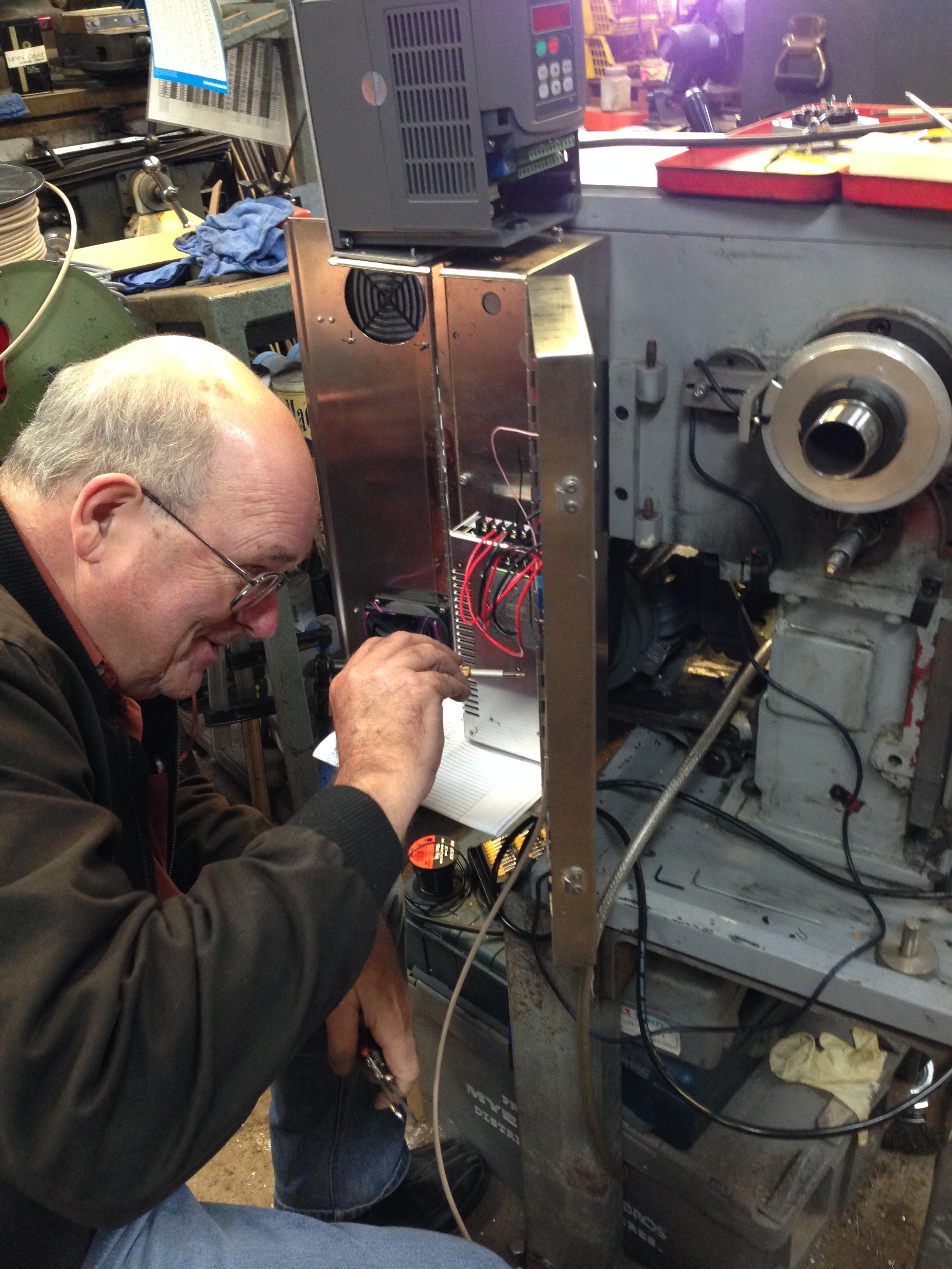
Hook ups in progress. That’s the faulty VSD on top of the electronics enclosure. The CNC engineer lost his hair trying to figure out the problem.
Still some testing and fine tuning required.
But nothing much will happen in the workshop for the next 3 weeks.
July 11, 2016
CNC lathe conversion -14
These lathe CNC conversion posts are probably becoming a bit tiresome, but just in case there is someone out there who is interested, I will continue until the job is finished.
The latest was to make and install a spindle speed (and position – thanks David M) sensor. It consists of a disk with a slot cut in the periphery, attached to the main spindle. And an opto-electronic sensor which is connected to its own electronic board, thence to the breakout board and VSD.
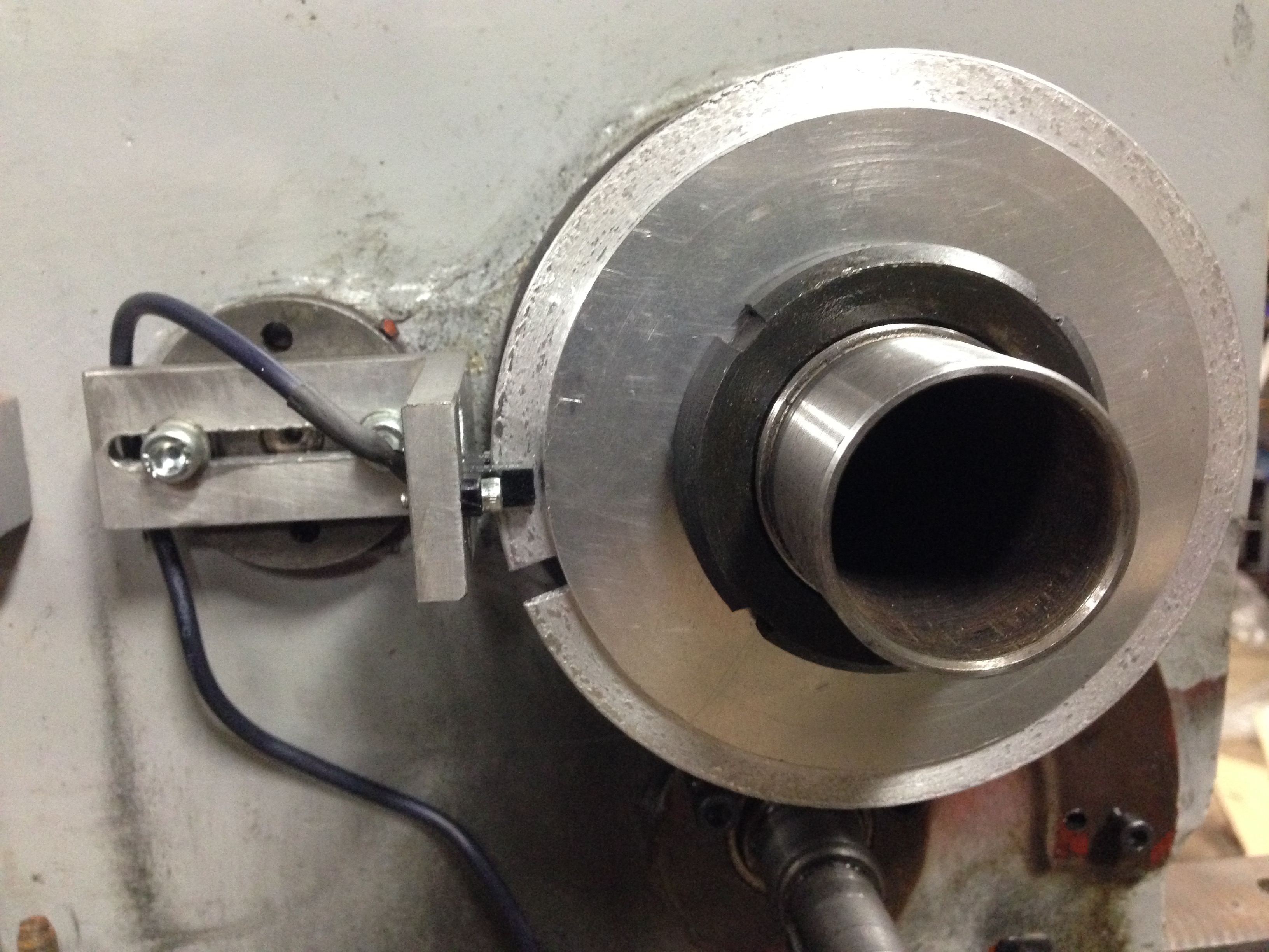
The disc with the slot at 8:30 and the sensor at 9:00. I must have chosen the wrong cutter or turning speed for that disc aluminium… looks a bit rough. (note added 13/7 Stuart T says that I should have used coolant-lubricant).
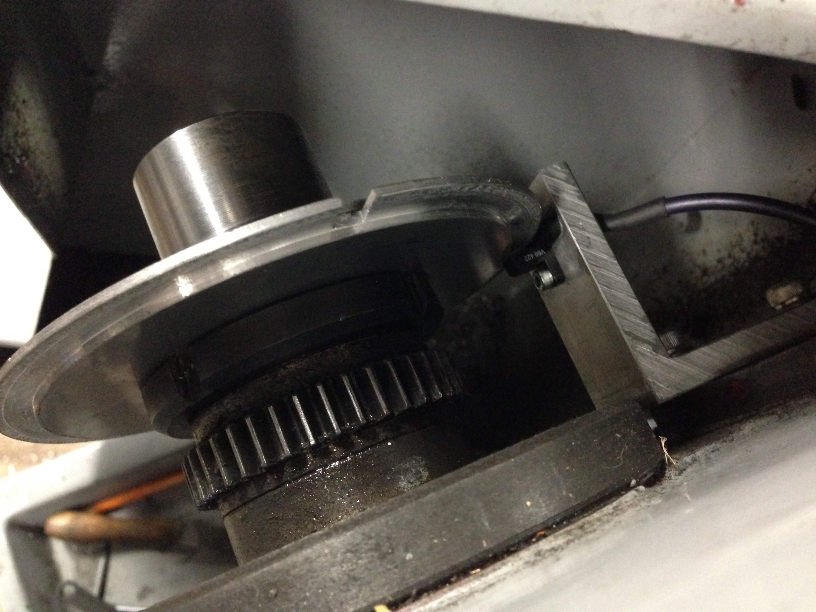
View from above. Any clearer? That gear is now superfluous except as a spacer.
So there is one electronic impulse per spindle revolution. That is enough to measure the RPM’s. Essential for cutting threads.
The beauty of this system is that there is no gear selection or changing, and ANY thread pitch can be selected… metric, imperial, BA etc… any odd ball thread that your heart desires.
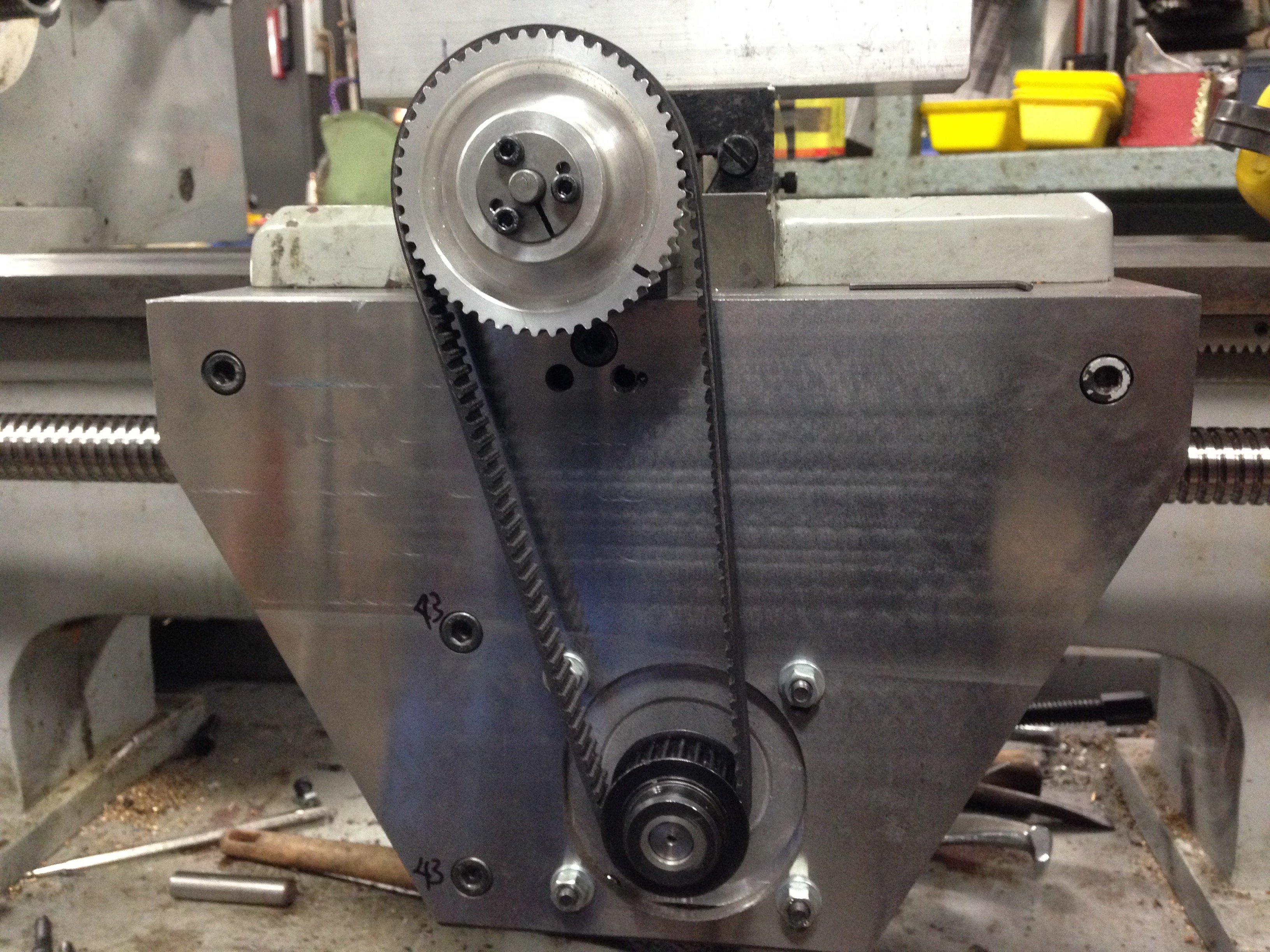
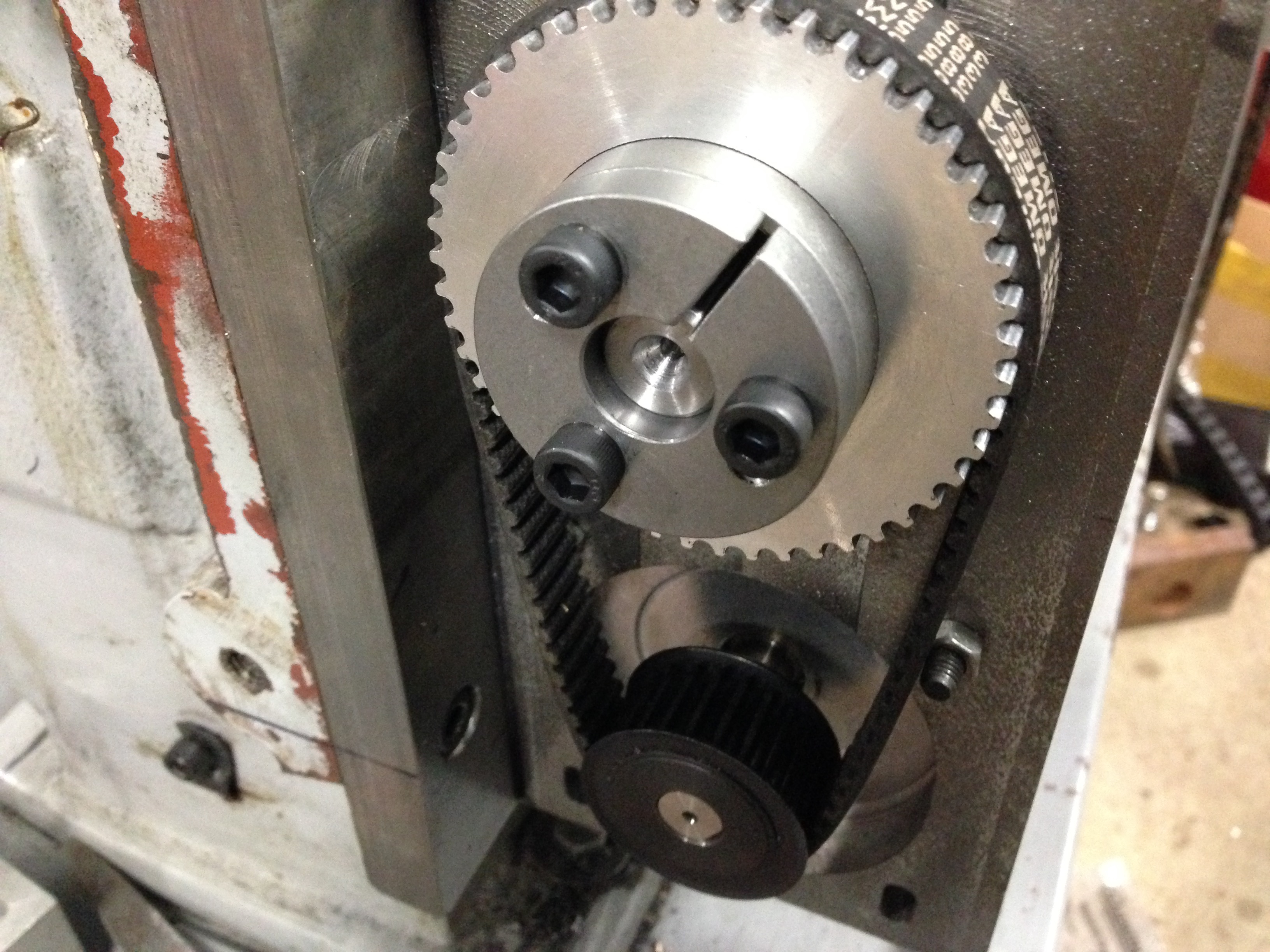
The HTD (high torque drive, I am informed by many readers) pulleys and belts and taper lock fittings. Unfortunately I could not find a taper lock to fit the small pulleys, so when it is all finally, definitely, absolutely, correctly, positioned, I will Loctite them in position. Protective covers yet to be made. I quite like to see the mechanicals in action, so I am intending to make the covers from clear polycarbonate.(Lexan) .
July 9, 2016
CNC Lathe conversion -13
Adjusting the lead screw.
The 48 tooth HTD pulley has been installed using a taper lock.
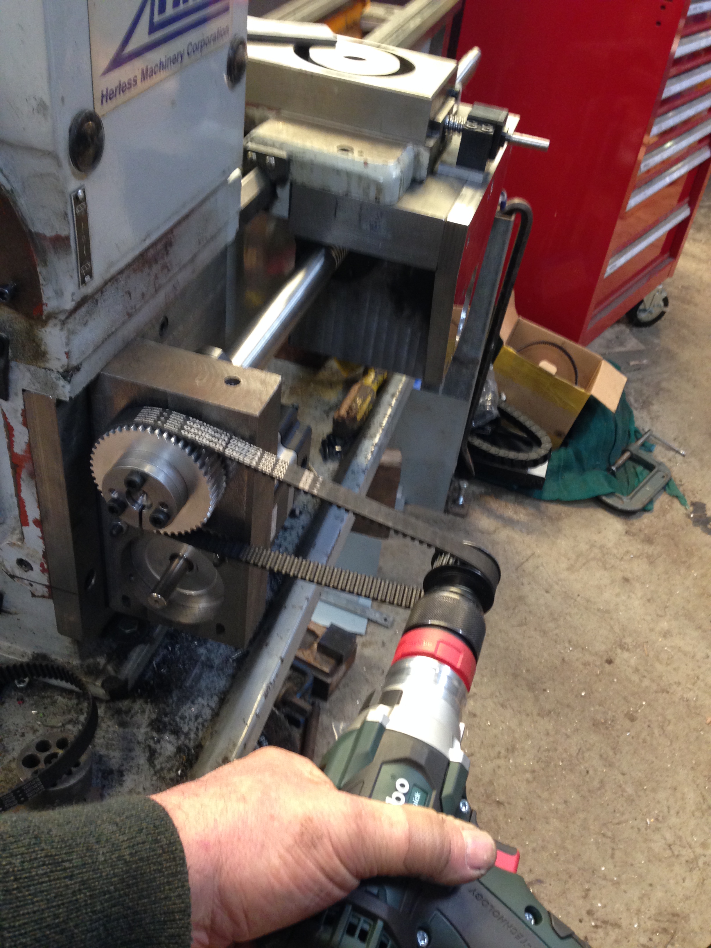
Then some time was spent adjusting the parallelism of the lead screw. That requires quite a few movements of the carriage along the 600mm thread. Each 360 degree turn of the lead screw advances the carriage 6mm, so you can understand that I became a bit impatient with all of the repetitive hand actions to move the carriage from one end to the other.
So this was a solution to that issue. That HTD belt is the one that was too long, so I was happy to find a use for it. The variable speed battery drill shot the carriage end to end in a couple of seconds.
All is now adjusted parallel.
A few more little installation issues, then for the wiring.
July 7, 2016
CNC Lathe conversion -12
Today I fitted the lead screw.
No big deal, I sense that you are thinking. After all, the ends are machined, the bearings fitted, and all waits in readiness.
True, but there is a strict sequence of events. And since it has been 3 or more weeks since it has been together, I had to rediscover the sequence, by trial and error. And each bit of the fitting is very heavy, very delicate, very tricky. So it took me several hours to get to the final photo in this blog.
But first a view of the inside of the newly machined apron.
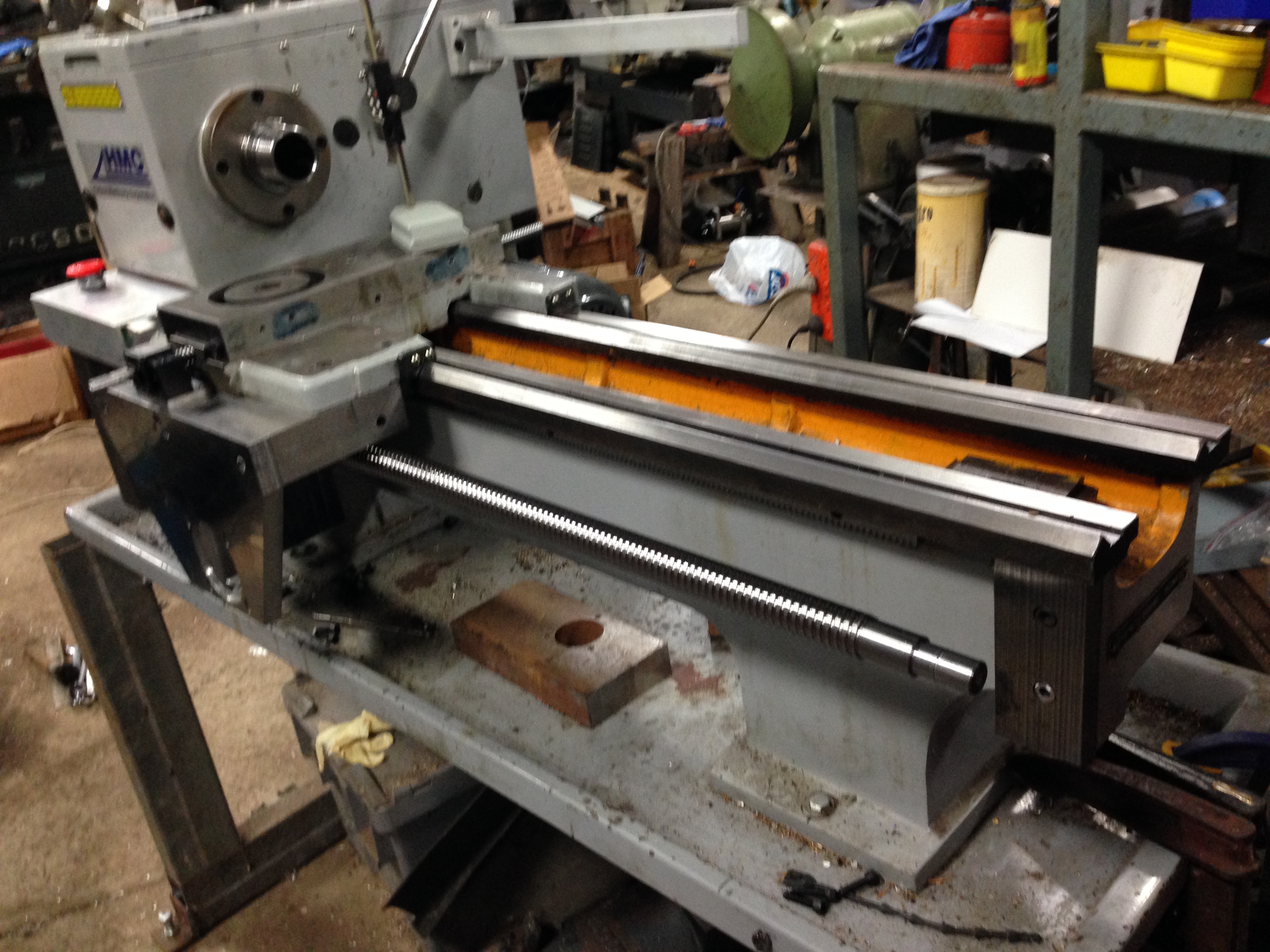
The lead screw fitted. The cross slide screw is also fitted. Note the red E Stop panic button fitted to the left. Next job is to fit a support bearing at the right hand end of the screw. Then to check and adjust parallelism of the screws. A rough check showed that they are within 0.25mm
July 4, 2016
CNC Lathe conversion – 9
The CNC lathe conversion has been happening, despite no posts on the blog.
I have mounted the electronics enclosure, and mounted the various components inside. No wiring yet.
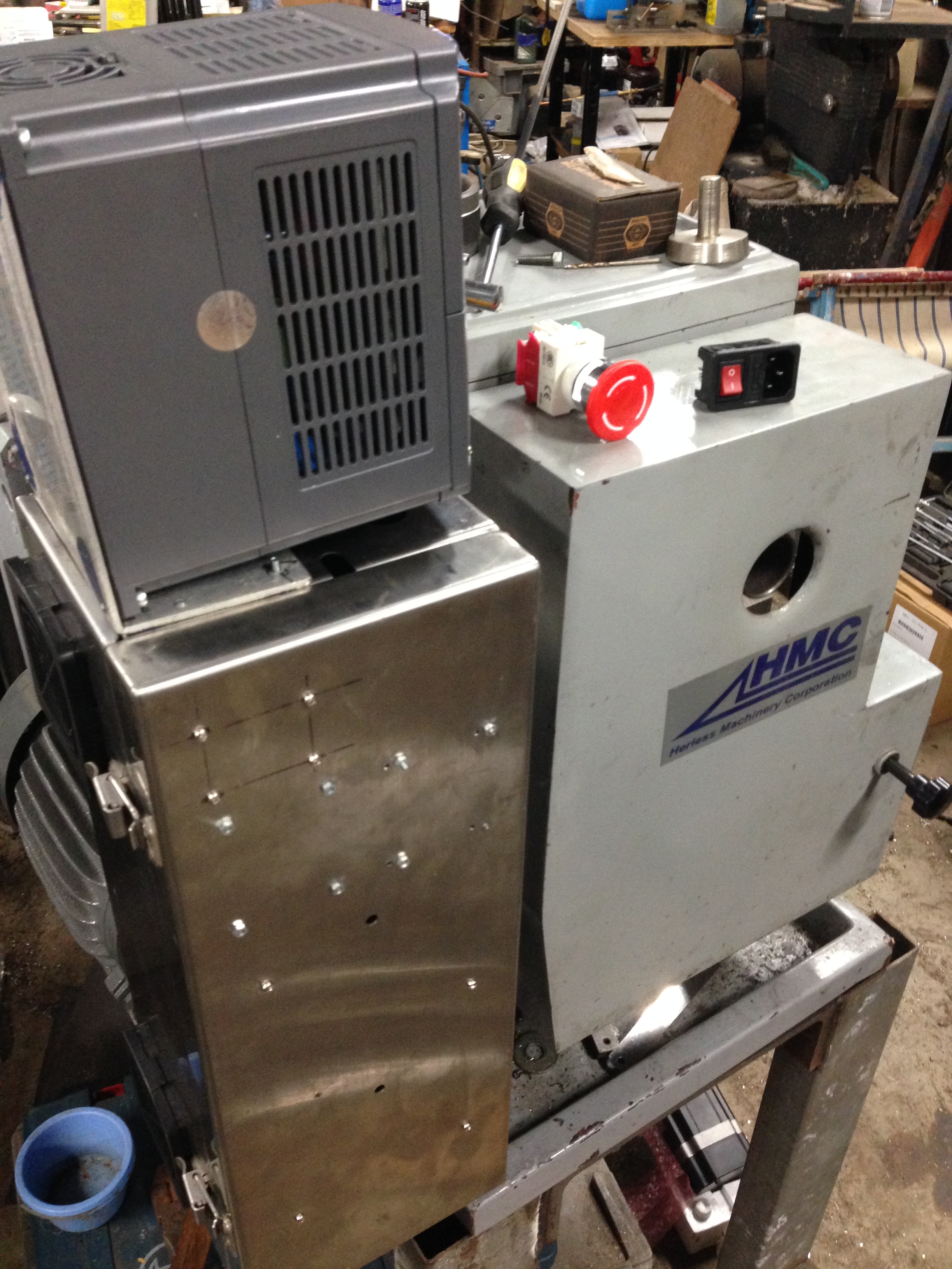
This stainless steel tool box is the electronics enclosure. It fits the space quite nicely, and is adequately big. The back gear cover to the right will be retained, although the back gears have been discarded. The main switch and emergency stop will be mounted somewhere on this cover.
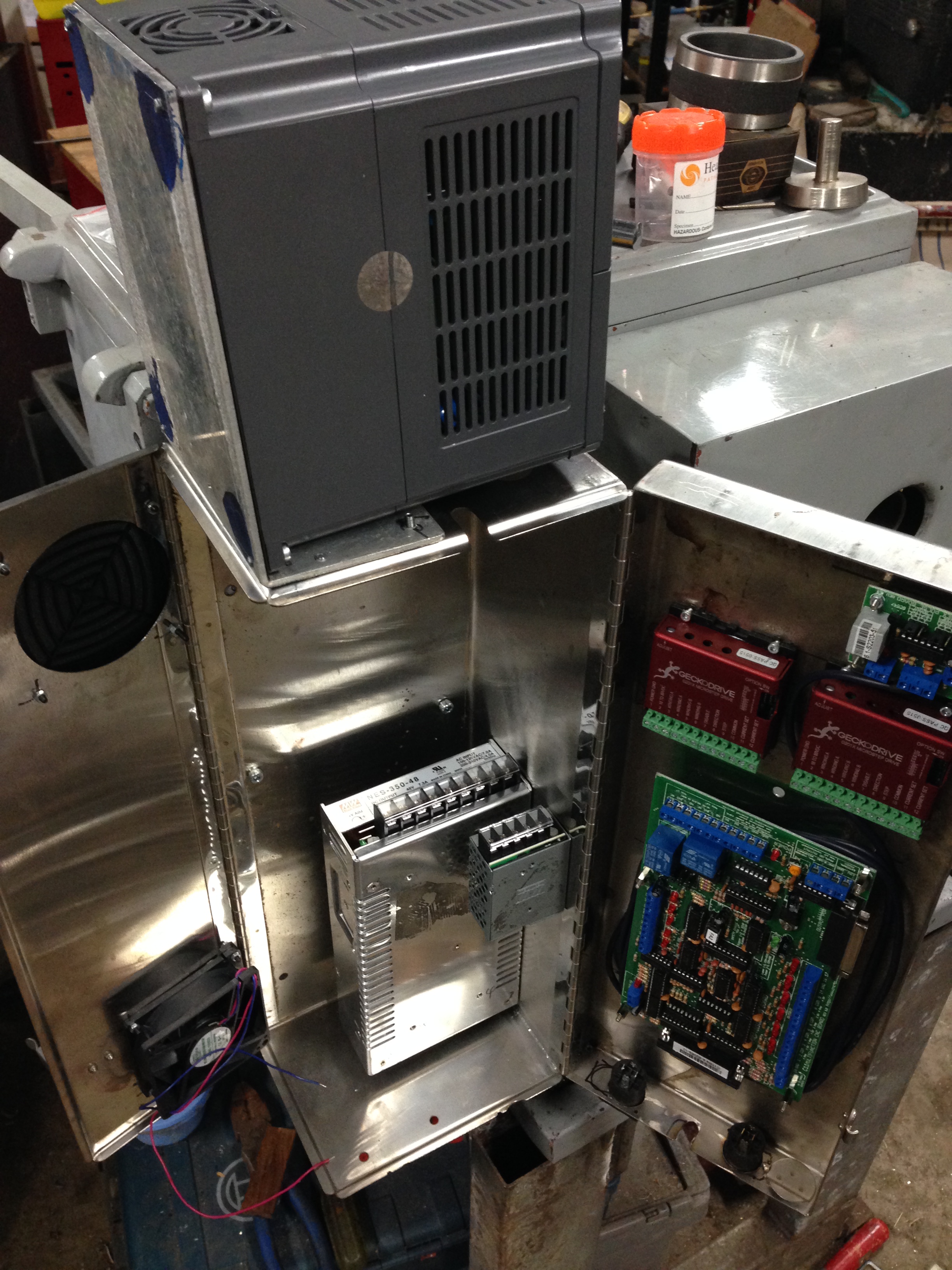
The Variable speed drive (VSD) sits on top. That will control the spindle speed. The transformers, stepper motor drives, and Breakout board (the heart of the system) are positioned inside. Plus cooling fan and filters. Ready for wiring.
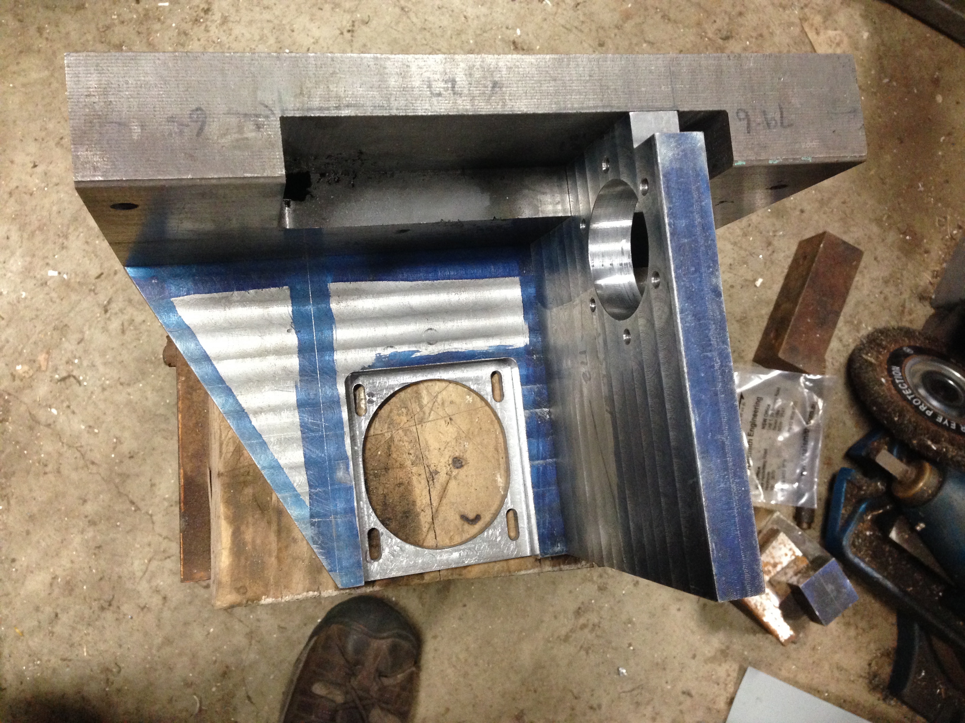
Drilling the apron to attach the cross slide ball screw bearing. One chance only at this one, so the setting up took a couple of hours. The apron is clamped to a large angle bracket on the milling table. M6 threading followed.
The end result. The bearing as attached to the apron and the ball screw is in place. I machined the end of this ball screw to fit the bearing, cut a thread (M10x1), and machined the end to accept the pulley. All good. There is 0.25mm adjustment available if required, but it all seems pretty correct. The bearing sits on a carefully machined block which is 7.85mm thick. Still waiting the lead screw machining.(!!)
