johnsmachines

machines which I have made, am making, or intend to make, and some other stuff. If you find this site interesting, please leave a comment. I read every comment and respond to most. n.b. There is a list of my first 800 posts in my post of 17 June 2021, titled "800 Posts"

Category: boiler

So Many Mistakes! Am I Too Old for this hobby? Or is it the heat?

Having completed the model Trevithick dredger engine, and not having an inspiration to start another major build, I decided to make another steam driven boiler feed pump.

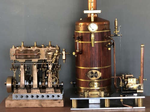
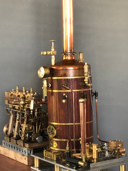
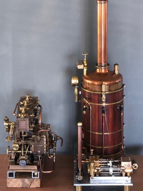
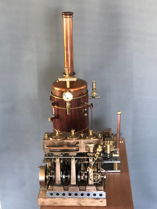
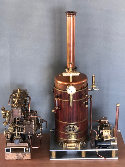
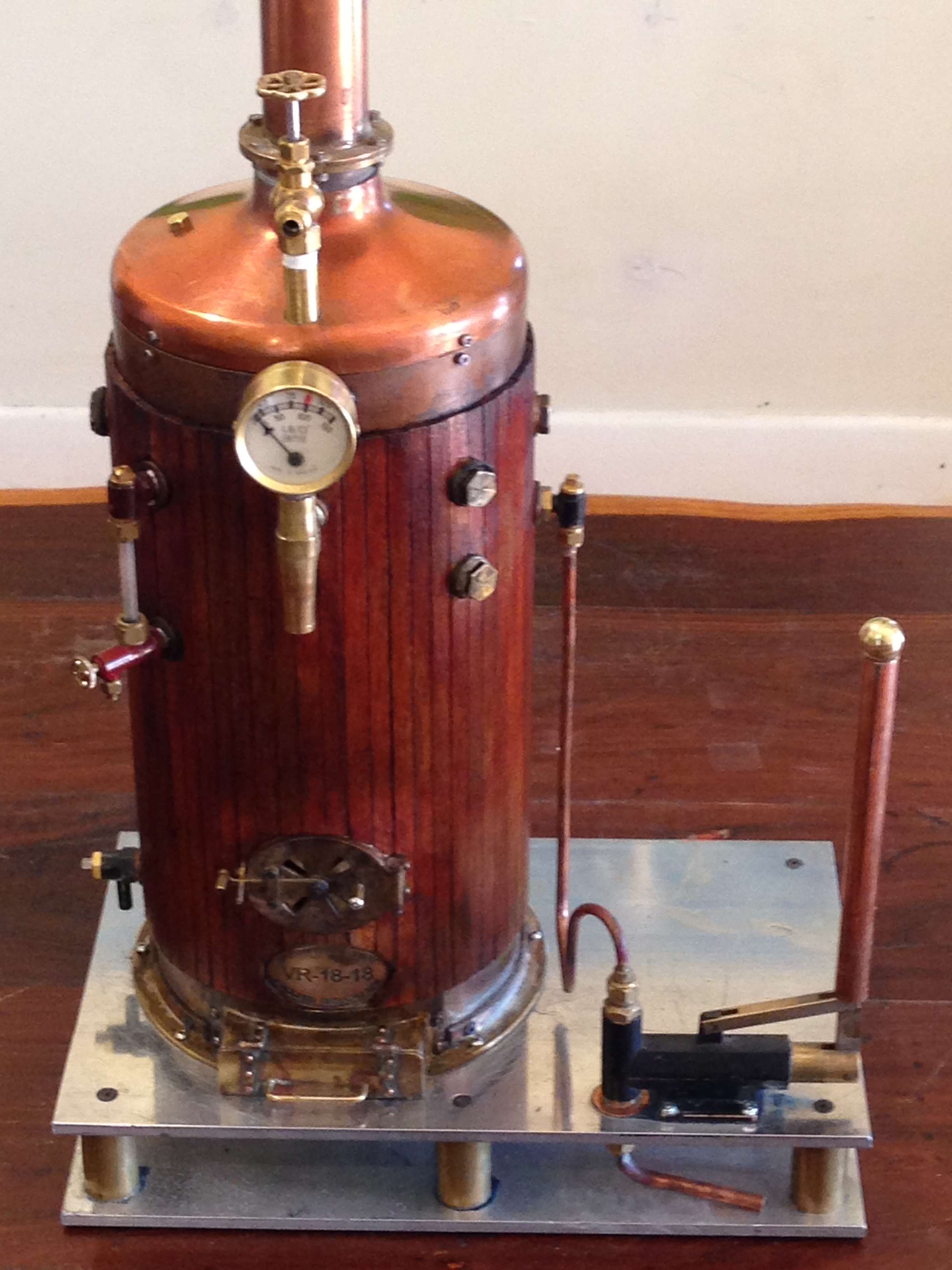
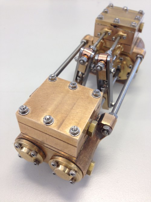
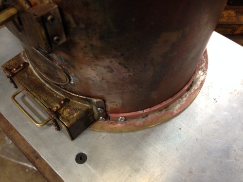
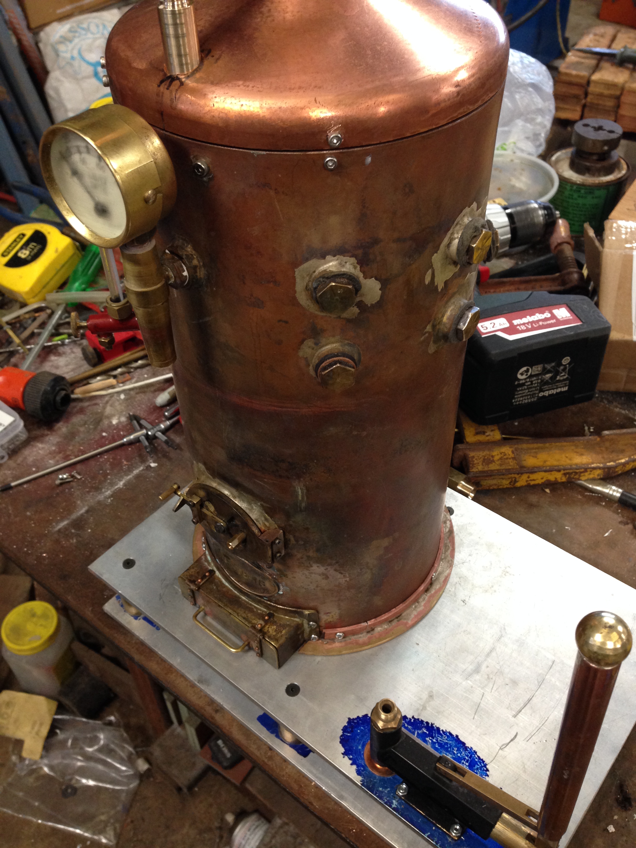
Earlier this year (2019) I made a horizontal, duplex, twin cylinder feed pump for the 6″ vertical boiler, but I had also purchased the castings and plans for a vertical, single cylinder feed pump, not having decided which version to fit to the boiler.  The horizontal twin version fits and functions very well, but I decided to make the vertical version while I am thinking about another major build.

Screen Shot 2019-12-30 at 11.01.18 am.png

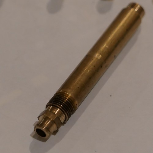
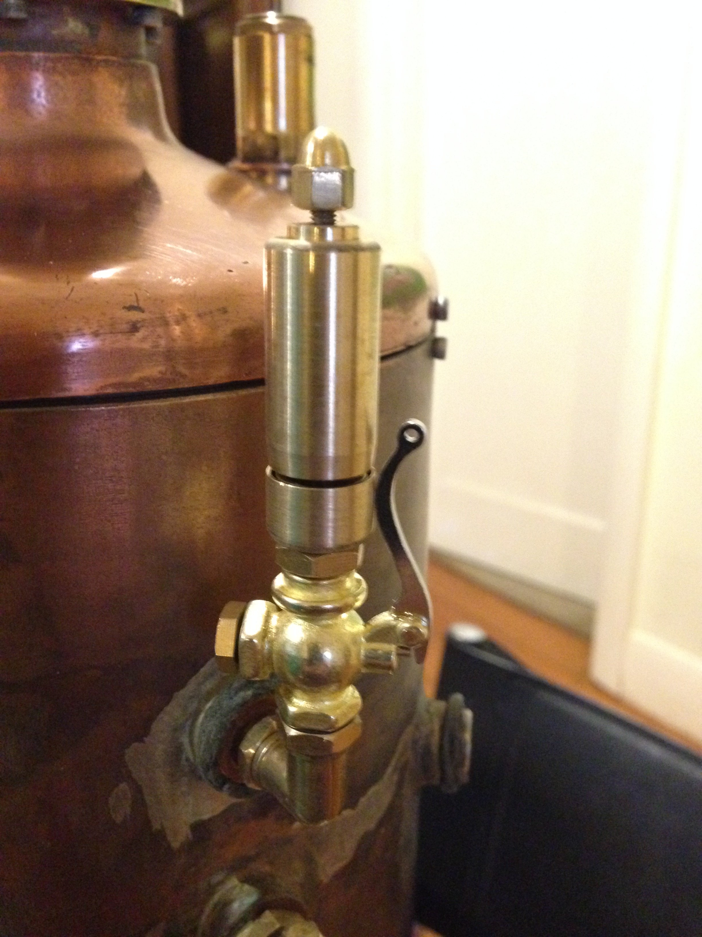
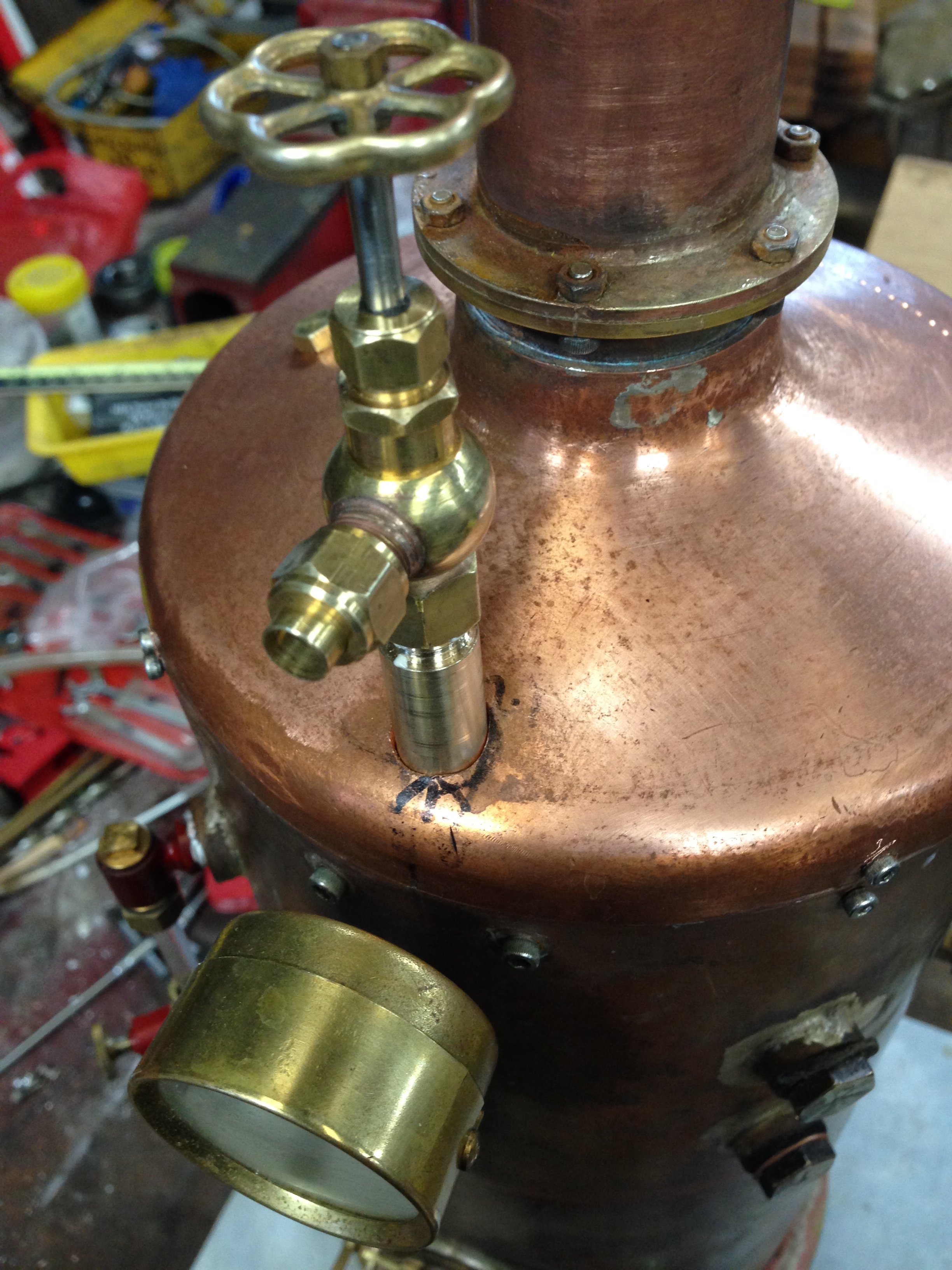
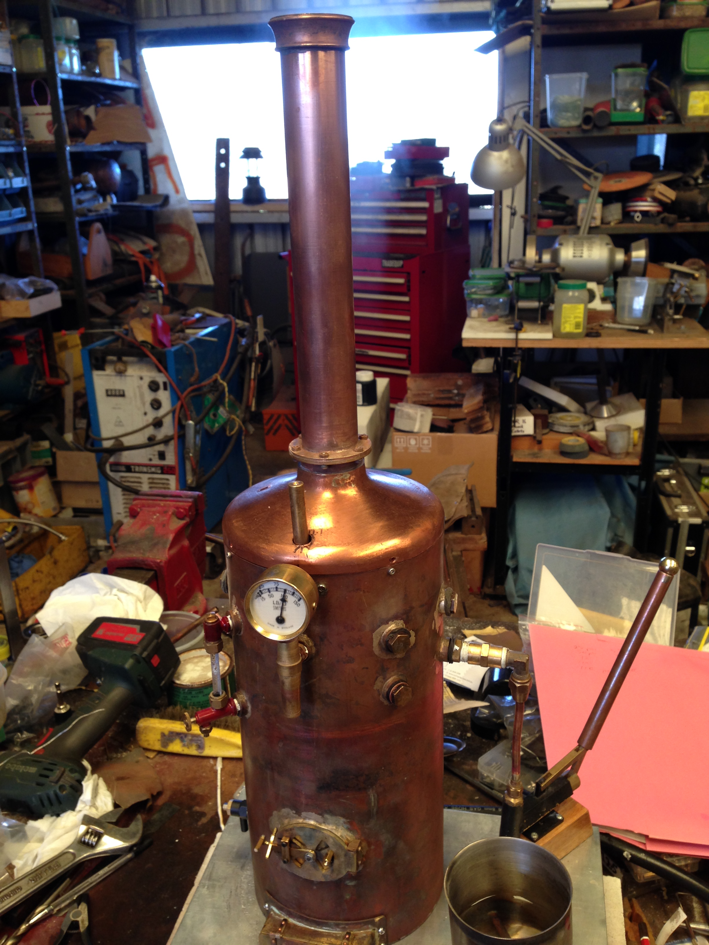
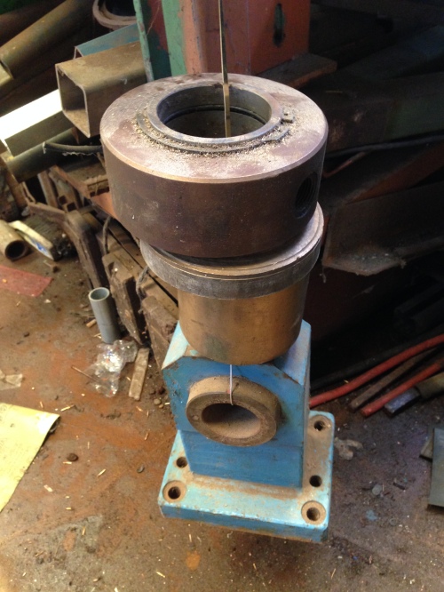
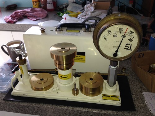
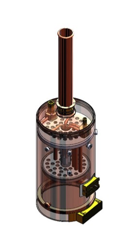
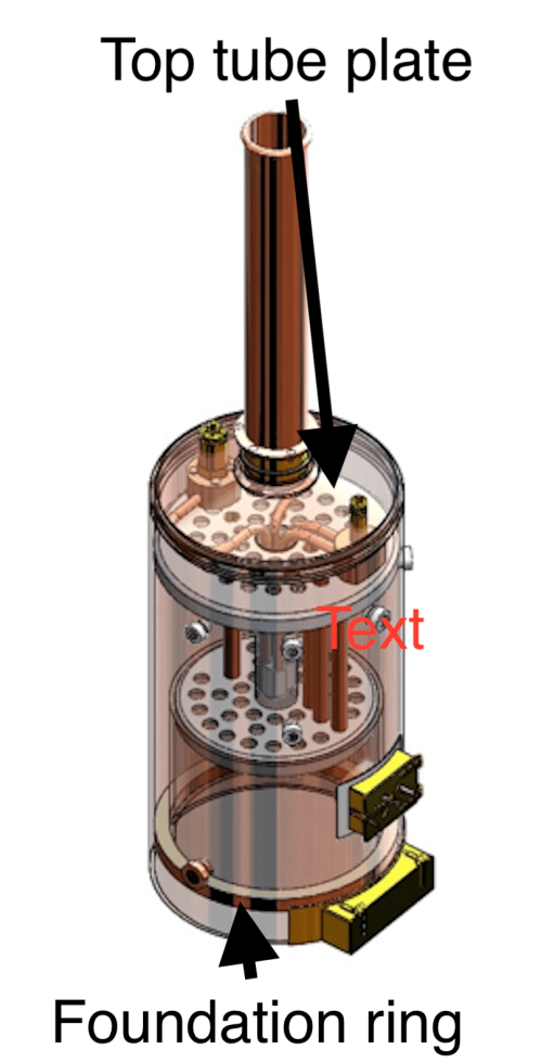
This is what it will look like.  Hopefully.  Single acting 3/4″ steam cylinder top, and 1/2″ water pump bottom.

P1053271

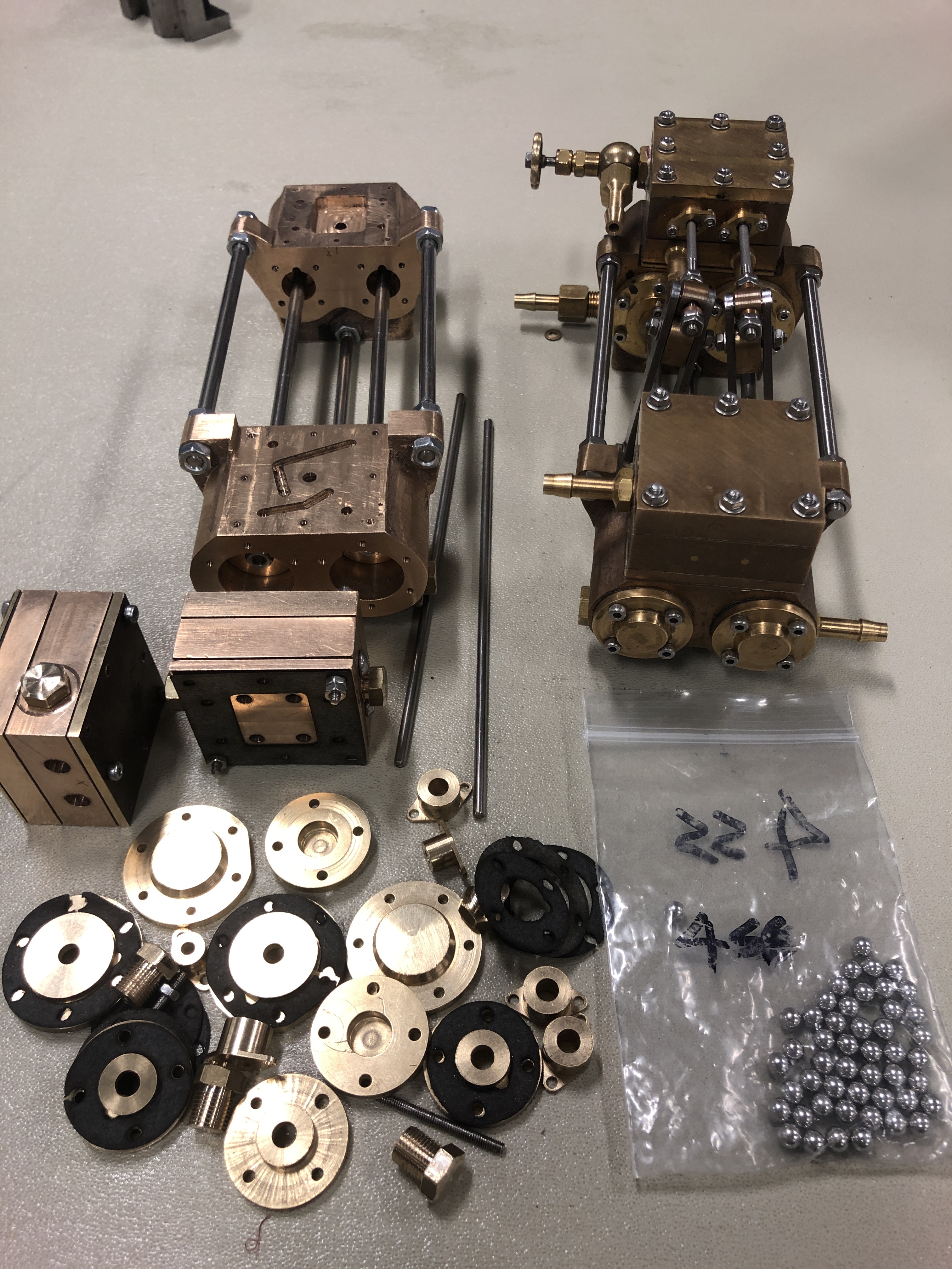
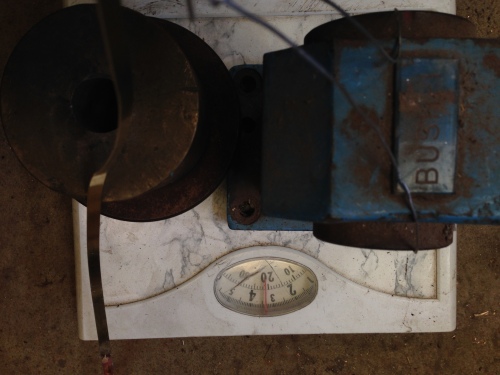
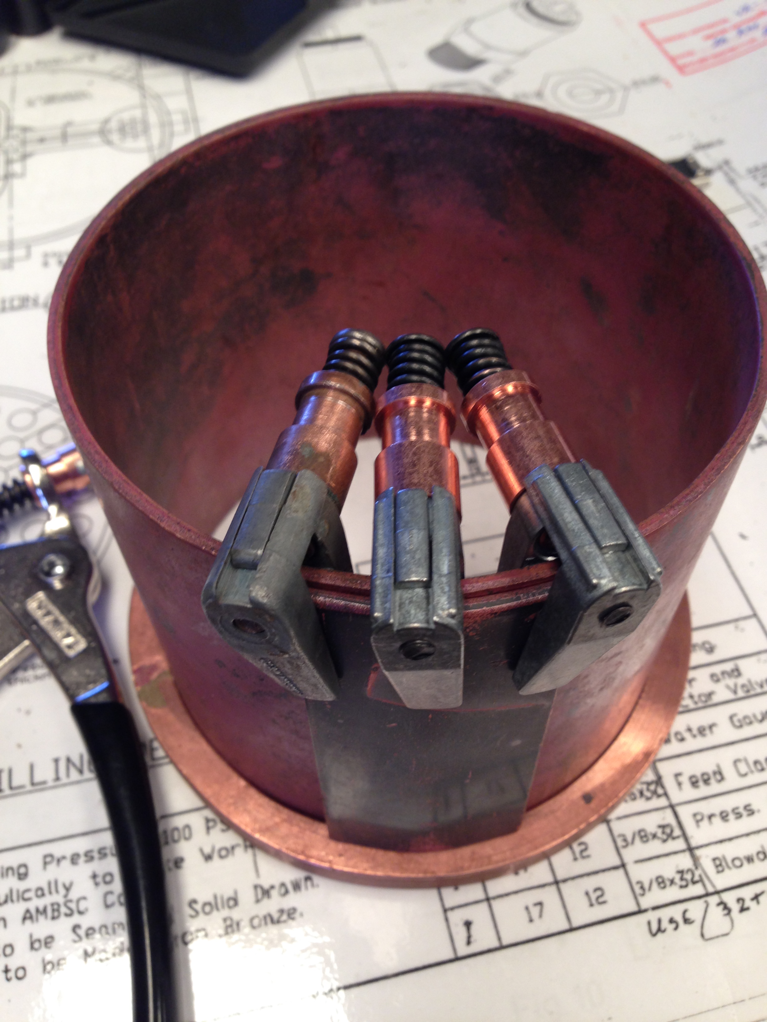
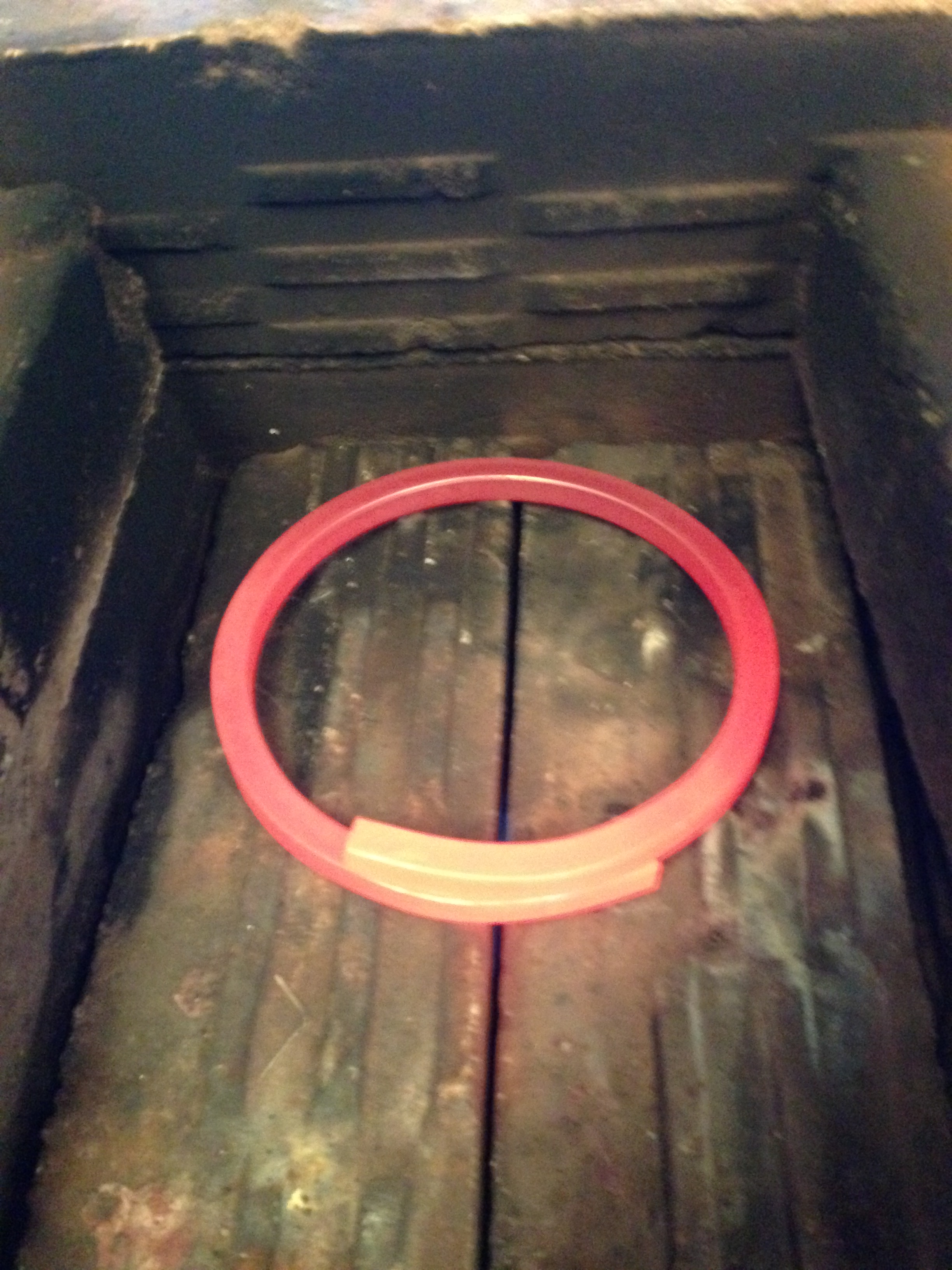
The plans, O rings and castings.  The castings have been cleaned up on the RadiusMaster, and the steam cylinder (top) is almost finished.

P1053275.JPG

The 7 pages of plans are excellent.  Imperial measurements and fasteners.  I will use metric fasteners.

P1053276.JPG

But I work in metric.

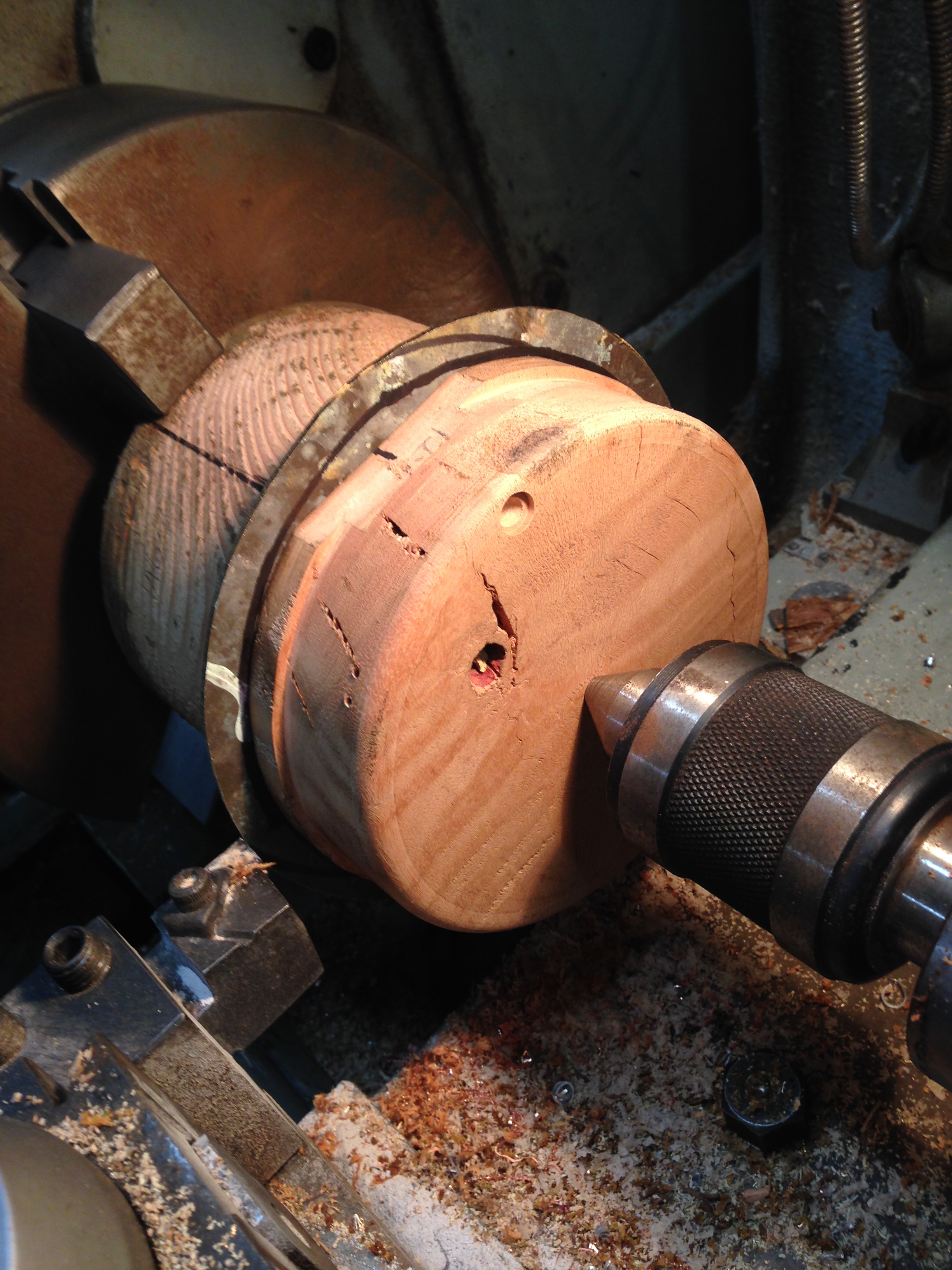
So over the past few days, excluding the ones over 38ºc (100ºf), I have been machining the gun metal castings.  And making a real mess of it.

The Mess.

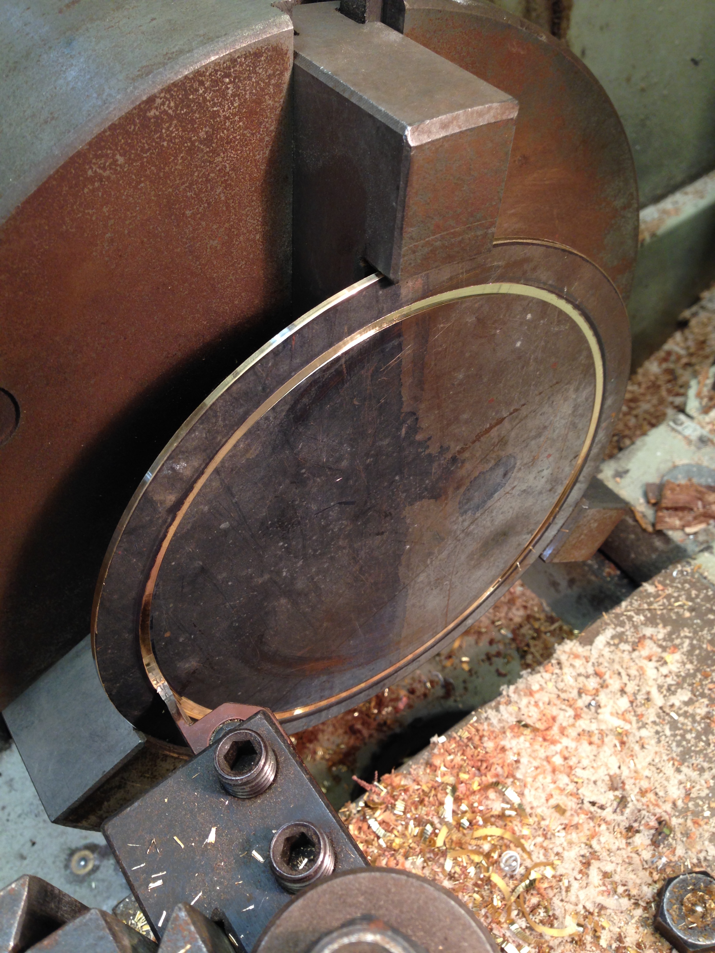
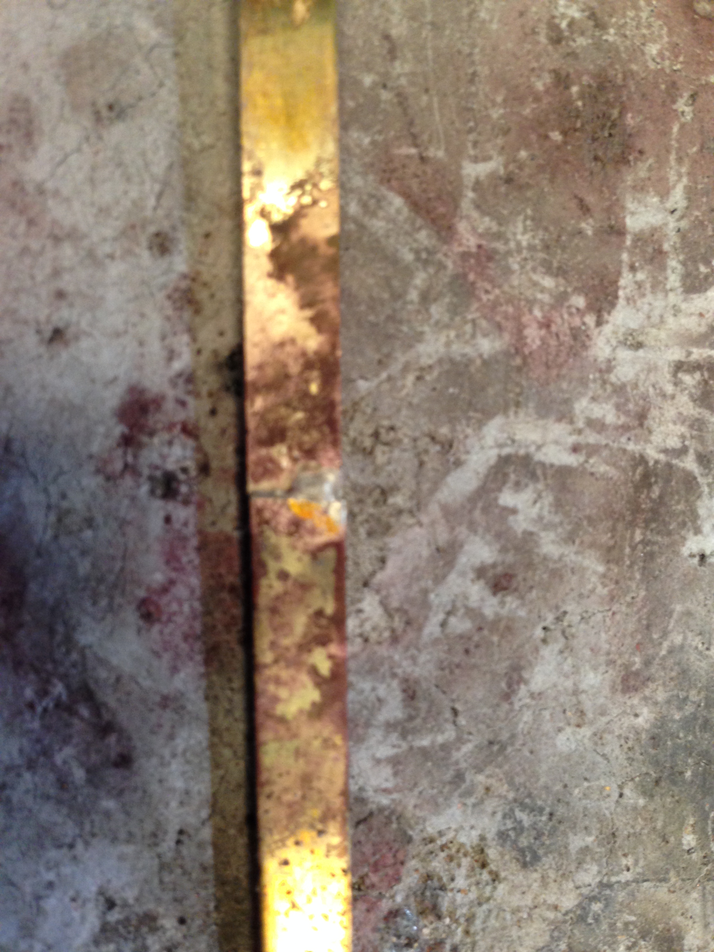
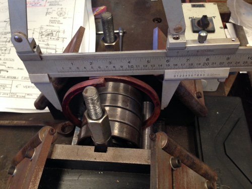
  1. The steam cylinder bore.  Bored with a boring head on the milling machine.  Turned out nicely, but I decided to run a 3/4″ reamer while it was set up on the mill, thinking that the dimension would be more accurate.  I did not notice until too late that the reamer was damaged.  It badly scored the bore.  I considered making a new cylinder from bar stock, but used the boring head to remove the scores.  Now 0.75mm oversize.  Annoying but not fatal.
  2. Steam passage not centered.
    P1053278.JPG

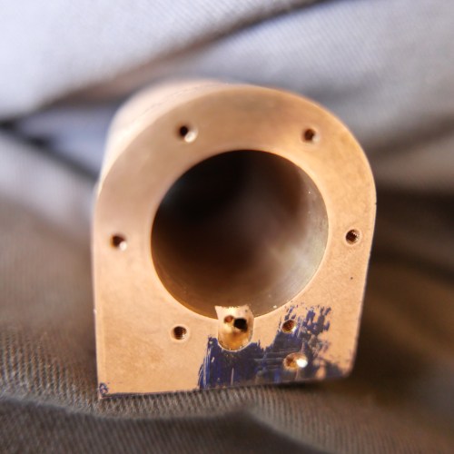
    The steam passage in the cylinder cutout is meant to be centered.  It is off at a 15º angle, and is centered with the cylinder top, but not the bottom of the cutout where it should be.   OK, it will not be seen, will not affect the function.  Just a trivial mistake.  That is the final oversize bore.

    3.  This one could have been fatal.  All of the center drill holes for the screws and steam passages in the cylinder valve face were off by about 1mm.  The workpiece had moved in the milling vice between setup and machining.  I really thought that this would probably require a new part, but I decided to proceed and see what eventuated.

    P1053279.JPG

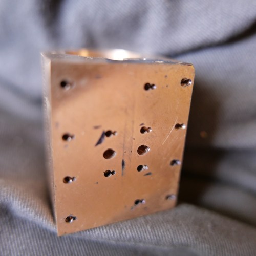
    The middle 6 holes are the steam inlet and exhaust passages.  Fortunately they are in the correct vertical position, and have just been widened horizontally by the incorrect centre drill holes, which should not effect the function.  The screw holes merged into the incorrect holes, and were pulled a fraction laterally, but should be OK.   At final assembly I will fill the incorrect holes with something, probably epoxy or gasket goo.

    4. This was the most obvious error.  Moved the mill table in the wrong direction, and the rectangular hole ended up with an extension.  I don’t think that it will effect the function.  And it wont be seen by anyone except me, and all of you blog readers.  Oh, and now I have to kill you.

    P1053281.JPG

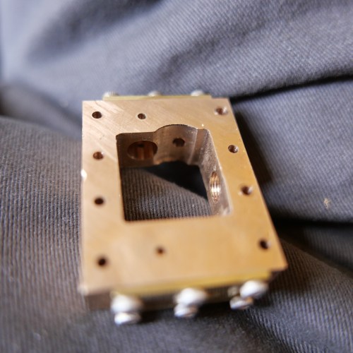
    Bugger bugger bugger

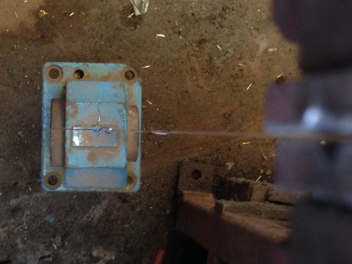
    5.  This was another mill problem.  I had changed the tools to a 1.6mm drill bit, and reset the Z axis zero.  Or had I?  Maybe I had neglected to hit <enter> after the reset.  Anyway, the chuck crashed at high speed into the job, impaling and snapping off the drill bit, gouging the steam chest, and the drill chuck gouged the milling vice.  The chuck survived but required some remodelling on the belt sander and then a diamond file.   The vice jaw also needed some impact craters to be flattened, then swapped out to another less critical vice.

    P1053282.JPG

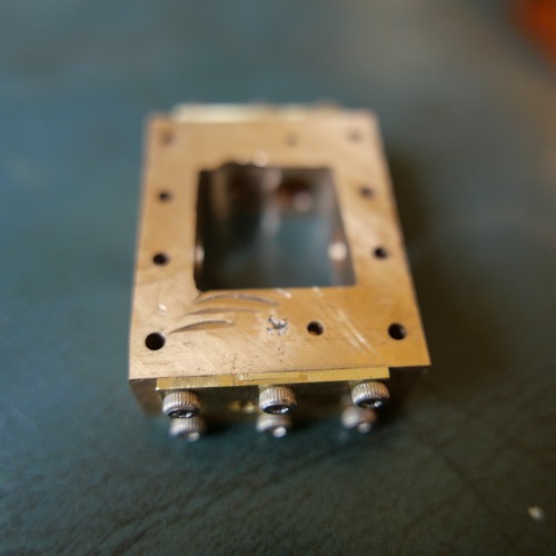
    I flattened the gouges in the steam chest face, and I will make sure to fill those with something at final assembly.  The embedded drill bit can stay there, after flattening it with emery paper.


There were some other more minor issues, which do not bear repeating and prolonging this missive.  This all happened over 2 days.  Mistakes are made, and I console myself with my father’s advice “he who makes no mistakes makes nothing”.  But, this is the worst run of blues which I can remember.   It IS hot, which is not ideal machining conditions.  So what do I do?

Well, maybe it is just a bad patch, and things will be better next session.  And, I will try to be not SO impatient to get things finished that I don’t double check.  I (and you) will just have to wait and see.

BTW, have a safe and happy new year. 2020.  It is 101 years since we had a double number year (1919), and most of us will not see the next one (2121).  So make the most of it!


6″ Vertical Boiler, Triple Expansion Steam Engine and Southworth Pump, all working together. Fairly well.

2 videos of the triple and the vertical boiler and the Southworth boiler feed pump working together for the first time.  Not perfectly yet, but working.


34 degrees. Is it summer already?

A beautiful spring morning became blustery, windy, hot yesterday.  But I hardly noticed.  I was in the workshop making these small steam pipe connectors.

Normally I would buy these fittings, because they are fiddly to make and not very expensive, but I have fitted new rings to the triple expansion engine, and I want to try it out on the vertical boiler.  (see the previous post)

P1033045.jpeg

one of the tails was not drilled deep enough.

P1033050.jpeg

I needed only 2 of these nipple-tail-nut assemblies, but having made a jig to fit the collet chuck it was just as easy to make some extras for future use.

P1033049.jpeg

The jig is required because having made one end of the nipple, it must be turned around to make the other end and there is not enough material to hold in the 3 jaw chuck.  So the jig holds the workpiece by the first made thread, and the piece is finished by holding it in the collet chuck.   The jig will be saved for future use.  It has external threads for  5/16″x32 and 3/8″x32, and internal threads for 1/4″x40 and 5/16″x32.

The tiny tails were drilled in 2 stages because there is an internal step, and the outer shape was CNC’d.


Thinking about future exhibitions….

Still recovering from The Royal Geelong Show, where my beam engine and the Trevithick      dredger engine ran for ~8 hours per day for 4 days, and required almost constant supervision. I was very pleased that they did so without a problem.

For future exhibitions I would like to also run the triple expansion steam engine using the vertical boiler, for which I recently made the Southworth boiler feed pump.  And there are occasions where I might run the triple and the beam engine together from the vertical boiler.  That arrangement will occupy a fair bit of bench space, and in this post I am considering options for the arrangement.

But first, I needed a steam outlet manifold to handle multiple engines, simultaneously, and hopefully to avoid a big tangle of pipes.  Here is the manifold.

IMG_8246.JPG

The manifold has 6 x ¼” outlets and one 3/8″  outlet.    

Option one lines up the boiler and engine like this….

IMG_8243IMG_8244

Option two is more compact, but ?less appealing.  Pics following..

IMG_8237IMG_8238

IMG_8239

The lump of wood under the engine is temporary,  just to give an idea of the heights.

OK, this post is just an excuse to show some pics.  I have decided to go with option one.  It is closer to the appearance if the boiler and engine were actually in a boat, and also will make it easier to add the beam engine to the right of the boiler if/when I run the two engines simultaneously.

And I doubt that I will be able to avoid a jumble of pipework.  The triple has 6 pipes attached, the boiler has more, then there is the beam engine.  And, I will need a water container from which to feed the boiler.  That will be located behind the boiler.  Still considering whether it should be a squarish box on a stand like the railway water towers, or a cylinder on a low stand.   Any thoughts?


Boiler Feed Pump Pumping

Yesterday I reseated the pump valves, reassembled the pump, then tested it on steam.

Most of the following video has the boiler at only 25psi, but I did run it off camera at up to 75psi.

After making the video I redirected the exhaust steam from the pump into the firebox.  It actually seemed to improve the gas flame, maybe by acting as a blower.  Not so sure about this being permanent though, because the exhaust steam contains oil from the displacement oiler, and I dont want that oil to be deposited in the firetubes.

I will make a water tank to supply boiler water.  Maybe the exhaust steam could be passed through a heat exchanger in the tank, so the boiler feed water is preheated.

(if the video is not showing, click on the https link below)


First Steam for Boiler Feed Pump


Mounting the Boiler Feed Pump

Today I mounted the Southworth boiler feed pump on the boiler base, then started on the pipework.  Nothing is tested yet, but it is looking interesting IMO.

P1032923.JPG

The Southworth pump, located behind the hand pump.

P1032919.JPG

The steam supply pipe on the left, and the water delivery pipe on the right.  The hand pump and the Southworth pump deliver water to separate clack valves on the boiler.  There is yet another clack valve in case I ever add an injector.  The water supply tank and connections are yet to be added.   I am not planning to install a bypass.  Note the displacement oiler for the valve chest.

P1032922.JPG

I tried a new trick to bend the pipes for this installation.  I read about this somewhere.  Bent a piece of wire to use as a pattern when bending and cutting the copper pipe.   Worked a treat!

Looking forward to firing up the boiler and testing the boiler feed pump on steam.  If it works OK there will be a video.


Boiler Feed Pump -Working

I could not induce my Southworth steam powered boiler feed pump to work.

Initially I thought that it was a bit tight, and spent time easing the glands, and slightly deepening the O ring grooves.  That took a couple of days.  But no luck.

So today I took it to our model engineering meeting, with some tools to perform a tear down, and 2 of our senior members took a close look.  After some to-ing and fro-ing, the verdict was that I had reversed one of the steam passage blocks, and machined it back to front.  I had mis-interpreted the plans.  It was due to not really knowing the rules for rotating a part in 3rd angle plans.  Pretty annoying.  A 3d view of the part would have removed any confusion.  Fortunately the fix was not too complicated.  2 threaded holes to fill, and 2 new holes to drill and thread on the other side.

That done, I re-assembled the steam engine side of the duplex.  Hooked up a compressed air hose, and see the result….

This is on approx 10psi air.  There is no load, so it is running faster than it would if actually pumping water under pressure.

Next I will mount it to the boiler base, and hook up the pipes.  Then there will probably be another video.

Southworth Steam/Water Pump

I am progressing my Southworth pump.   Today, Stuart brought his completed version, so I photographed the incomplete and complete versions together.   Actually, it was very useful to see Stuart’s pump again.  An obvious difference in one of the components made me realise that I had made a mistake.   Now rectified.

IMG_8181.JPG

My incomplete version and the working version.

IMG_8179.JPG

Stuart’s working version.

Hydrostatic Trevithick Boiler Test

This is a video showing how I performed the hydrostatic test on the boiler.

The engine is currently being made, but not at the time of the video.

The test is to hold water at double the working pressure of the boiler, for 20-30 minutes, checking for bulging or distortion of any of the components, and any significant leaks.  Any leaks would need to be fixed, but for the boiler certification, as long as the pressure can be maintained for the duration of test, that is OK.

The working pressure of this boiler will be 50psi, but the minimum pressure in the AMBSC code is 60psi, so the hydrostatic test will be done at 120psi.   As you will see in the video, the pressure reached 140psi at times.

In fact, the AMBSC code is formulated in terms of materials and design to cope with 8 times the working pressure, so the safety margin is generous.

The video is taken over 20 minutes.  I ran the actual test for over an hour.

I am afraid that my very messy bench and workshop are evident in the video.  No apologies.  That is just the way that I work.


Back to the Trevithick Dredger Engine

The 6″ vertical boiler is virtually completed.  Well, actually, I still have to make a Duplex steam pump, fit a steam injector, make a steam delivery manifold, paint some bits….  but yeah, emotionally, for me it is finished.   I will get back to those bits as the mood takes me.

So I have picked up the bits of the Trevithick steam dredger engine.  I will concentrate on the boiler, so I can get the AMBSC certification, then take a leisurely approach to the engine.  You know, 2 weeks to the boiler certification then another 4 weeks to finish the engine.  Or something like that.


IMG_6869.JPG

As you can see, I have redesigned the inspection hatch, and made the new version.  This is still not quite authentic, but it is much closer to the London Science Museum example.  The inspection hatch will be permanently closed, silver soldered shut.   And the wording reflects the fact that this is a model.  The model hatch is circular, whereas the LSE example is something between a circle and an ellipse.   Trouble is that we do not know what is original Trevithick and what was altered in 1870.   So I do not feel too guilty that I am guessing.


IMG_6868.JPG

Sorry about the poor focus.  I will retake this shot later.  You can read my new AMBSC ID number.  I do feel presumptuous writing my name the same size as Trevithick.


IMG_6867.JPG

I have marked the boiler perforations and will drill the holes then make the bronze bushes.


B002617 hi res

A hi res photo of the dredger engine in the LSM.  You can see that the inspection hatch is something between a circle and an ellipse, not a rectangle. And that firedoor hinge is definitely sus.


How does a 6″ vertical boiler enhance house decorating?

When I was making the 6″ vertical boiler, SWMBO commented, “you needn’t think that is staying in the house!”

Well, she did say,  after the boiler bands went on “Hmm.  That looks quite interesting”.

So I took that as my invitation to put it somewhere….  in the house….


IMG_6863

This desk is just inside the front door.  The boiler sort of melts into the background, don’t you agree?   SWMBO has not spotted it , yet.


6″ Boiler Lagging -3, and back to the Dredger Engine.

The brass bands which secure the wooden lagging strips were installed.  5 bands were required to make sure that every piece of wood is held once the glue lets go.  The bands are only 4.75mm wide.   The bolts which apply the tension pass through small brass blocks which are silver soldered onto the ends of the strips.  (thanks Ben De Gabriel of EJ Winter for that tip!  And for the band material!)


IMG_6860.JPG

The boiler sitting on our kitchen table.  I will eventually paint the ashpit door assembly and angle plate at the base.


IMG_6859.JPG


IMG_6857.JPG

The setup for holding the small blocks in position during silver soldering.  In order to not close up the gap between the small block and the brass strap, I centre punched the blocks, raising small dimples, which produced a thou or two of separation between the parts, allowing the molten silver solder to flow.  That silver solder wire is 0.5mm diameter. 


And back to the Trevithick Dredger Engine….


IMG_6855.JPG

The redesigned inspection hatch.  The bronze rectangular bit plugs the hole in the end plate.   I have plugged the unwanted 14 holes in the end plate, using stainless steel threaded rod.   And metal worker’s hands, cut, dirty, dry thick skin (SWMBO “don’t come near me!”).


FullSizeRender 10.jpg

Four of the plugged holes around the firebox opening, 10 more under the inspection hatch (hidden), and the inspection hatch.  I will make the inspection hatch a little bit smaller.  It will be decorative, permanently attached and unable to be opened.  The dredger engine in the London Science Museum has the manufacturer’s name cast into the plate.  I am contemplating just inserting Richard Trevithick’s name and the date the first high pressure engine was made (1806).  There will need to be a separate area on the boiler wrapper the AMBSC identification.


Boiler Lagging -2

The Tasmanian Oak lagging looked too pale white to my eyes.  With use, steam, oil, dust, water, workshop grime and sunlight, it would have gradually acquired a well-used patina, but I prefer instant gratification.

IMG_6842

So after consulting my resident wood finish, artist, architect, expert, (SWMBO), I applied some wood-stain.


IMG_6846.JPG

Too orange, too patchy, she said.   And the white in the joins looked wrong.

Too orange, too patchy, and too much white showing.  “Put on some black boot polish” she directed.

So I did as I was told.


IMG_6848.JPG

With a boot polish brush…


IMG_6851.JPG

—and a toothbrush…


IMG_6852.JPG

… hmmmm.   I better clean her toothbrush before putting it back….

…(acknowledgments to Tubal Cain for using his old gag…)


IMG_6853.JPG

That’s the look I was wanting.

Now just waiting for the brass bands to arrive.

Ben De Gabriel from EJ Winter, Sydney, had sent me a remnant piece of banding to try, in my last consignment of parts from him.  It was perfect, but not enough for the 5 bands which I require.  So I rang him.  He thought that was the last of his stock of that particular size but he would check and let me know.  Sure enough, he returned the call, and he had found a couple more bits, and they would be just enough.  Old stock, a bit shop-soiled he said.  So I could have it for nothing!

Readers who have been with me for some time will know that I have bought 3 sets of engine castings and plans from EJ Winter.  The Bolton 7 horizontal Mill engine, the Bolton 12 Beam engine, and the Bolton 9 triple expansion engine.  A bit of very interesting news is that Ben is planning a new set of castings for the triple, using the lost wax casting technique, which gives a finish which should require machining on the mating surfaces only.  That sounds so good that I am almost tempted to make another triple.   Almost.   Some months until availability though.  (Hope that you don’t mind my premature announcement Ben.)


6″ Boiler. Lagging.

Lagging.  As in boiler insulation, not as in failing to keep up.  I have been working on the boiler for about 3 months, so I am actually happy with the progress.  And more than happy to have passed certification!

I decided to apply wooden lagging strips for the appearance and for ease of handling, rather than any minimal improvement in performance of the boiler.

After use, the boiler shell is too uncomfortably hot to handle, so there is a waiting time of 30 minutes or so to allow it to cool.  I am hoping that wooden lagging will reduce the waiting.

And wooden lagging will hide the splodges of silver solder around each boss and join.  And it looks the part IMO.

But how to attach it?  None of my books mentioned any method.  I presumed that the brass strips are the main method, and that is certainly so, on full-size boilers.   Then I found a short video on YouTube by Keith Appleton and I decided to copy his method.

The method uses Super Glue as a temporary securing method while positioning the strips, then applying brass strips to hold the wooden strips in place long term.  The boiler heat and expansion-contraction will result in the glue bond being temporary, and if the wood strips have to be removed later, for any reason, that will be possible. It also means that an insulating blanket cannot be inserted between the copper shell and the wooden strips, but I was not planning on using a blanket, so not a problem.


IMG_6821.JPG

The strips are 3x8x265mm.  I chose Tasmanian Oak which is actually an ash, because it is hard, fine grained, and I had some in old floor boards.  I cut the pieces to length a bit oversize, then ripped them to size on the bandsaw.  It is difficult to avoid fingers being close to the blade with small pieces like this, so I used a push stick.  I needed 65 pieces.  The blade teeth are a bit too coarse for this job, but I was too lazy to change it for a finer one.  Note the saw blade guide.  I did not like the one which was provided by Metabo, so I made that one.  Works well!


IMG_6822.JPG

Then I used a belt sander to remove most of the sawing marks.  The resulting thicknesses varied from 2.8 to 3.4mm but I hope that variation will not matter.


IMG_6824.JPG

Some hand sanding to remove wood fur.


IMG_6829.JPG

Hope that this will be enough pieces!


IMG_6830.JPG

The boiler feels out of place in all this woodworking rubbish.


FullSizeRender 18.jpg

SWMBO was away, so I set up on the kitchen table.  Here deciding on the final length of the strips.


IMG_6835.JPG

Each piece is cut to length, then fitted into position.  Shaping the wood to fit around bosses and fittings is done with a small sanding drum in the Dremel.  It is a slow process.  Then each piece is glued into place, and held with rubber bands.


IMG_6836.JPG

It has taken about 4 hours to apply about 1/3 of the strips.  The Baileys was to keep me in an appropriate mindset.  I am looking at the slightly ragged top and bottom edge in the photo.  Looks a bit rustic and authentic, or just rough?   The wood will be darkened after oiling, and possibly staining.  And Tasmanian Oak darkens with exposure to light.

That was yesterday.  Today I hope to complete this job, but SWMBO is home, and not appreciating the dust and mess, so I am exiled to the outside.

I have realised that to secure all of the wooden pieces I will require 5 brass bands.  I do not want it to look too brassy, so I am ordering narrower strips than the 6mm material which I had previously bought.  I think that 4.75mm will be about right.


VR-18-18

VR-18-18 Stands for Victoria, Geelong Society of Model and Experimental Engineers, 2018, 18th registered boiler for the club.

So this morning I fired up the boiler with the boiler inspector closely watching.  The gas was turned to maximum, and the water was showing full.

Steam appeared about 10 minutes later and the Sandberg safety valve started popping at 100 psi. Every couple of minutes the safety valve released and the pressure remained in the 97-100 psi range.  This went on for about 20-30 minutes.  All to the satisfaction of the inspector.

He was happy with the standard of the build, the pressure test, the accumulation test, and that all requirements had been met.

The boiler is now certified for 4 years.  There has been a change in protocol about which I was unaware.  The previous certification rule was for 12 months only, and retesting was required for a further 3 years.  So this new rule is much less time consuming for me and the inspector.  He is happy that before the next testing I will have a steam pump and a steam injector installed.

IMG_6817.JPG

I was so delighted with the result that I treated myself to a trip to the non ferrous metal supplier, and bought a selection of hex brass stock for the workshop.  When I returned to the workshop there were still a few hours of daylight, so I spent the time making the new inspection hatch for the Trevithick dredger engine.  Not quite finished, so no pics yet.

The next step for the boiler is to make and attach the wood lagging and to put on some paint.

A steam driven water pump, and a whistle.

Boilers, whether full size or model, get through substantial volumes of water.  When my 6″ vertical boiler is working hard, so is the water pump, to replenish the water which is turned to steam.

At present, the water pump is a manual pump, and it needs to be operated almost continually when the boiler is steaming hard.

IMG_6791

I am not sure whether operating the hand pump (lower right), or the propane burner, consumes more energy.

So it was with great interest that I viewed the steam pump in operation which was built by Stuart Tankard, at last night’s meeting of GSMEE.  I have plans and castings for the same unit, and expect to make it later this year.  It is a Worthington type pump, and the castings and plans were supplied by Southworth Engines.

IMG_6664

Stuart’s latest.


In this video, for the demonstration, the pump is running on very low pressure compressed air.  The larger cylinders are the steam powered driving cylinders, and the smaller ones are the water pumps.  So whatever the pressure of the steam, the water pressure will be greater, and able to be pumped into the boiler.

And finally, I bought a steam whistle.  It was supplied by Microcosm.engine from China and it was very reasonably priced. ($US39).  I have not tested it yet, but it came highly recommended by Keith Appleton.  It is certainly very nicely made.  I screwed it onto the boiler as a bit of bling because I showed my boiler progress at last night’s meeting of GSMEE.

IMG_6790.JPG

Almost ready for the boiler inspector.

Almost ready for the boiler inspector!

It feels like the countdown to the finals medical exams!

So today, I drilled the gas jet from 0.22mm to 0.3mm.   A drill bit to drill 0.3mm, is, at least to my eyes, barely visible.  It is finer than the finest sewing needle.  If I pick up a 0.3mm drill bit I can not feel it.  It has no discernable weight.

So this is how I increased the jet size from 0.22 to 0.3mm.

Oops!  I forgot to take a photo.  I bought a set of micro drills from Jaycar, and the smallest bit was 0.3mm.  So I mounted it in the Dremel, and ran it at 10,000 rpm.   for a vise I used my fingers.  The drill went straight through the millimeter or so of brass with no detectable resistance.   Managed to miss my fingers.

0.22mm to 0.3mm diameter is almost a doubling in area of the jet orifice, so I tested the flame.  It was (not surprisingly) much bigger!   And still a good blue colour, with minimal yellow.  So I stopped there.   I also installed an adjustable propane regulator Huib.

Then I made an angle piece to secure the boiler to its baseplate.

IMG_6783.JPG

I needed a non rusting disk, 165mm diameter, with a 152mm hole.  The disk was 2mm thick.  So I roughly bandsawed it out in 2mm brass sheet, then set it up in the lathe as shown above.  Turned the outside diameter.  The brass sheet is held just with pressure between the headstock and the tailstock, and the disks of wood.

IMG_6784.JPG

Then I held the disk in the 3 jaw chuck and used a parting tool to cut out a disk to form the middle.  The waste middle came out with a bang.  I was careful to stand to the side, anticipating the decapitating scythe.   And I was not disappointed.  I did have to check that my head was still attached.

IMG_6785.JPG

Again, I was so involved with the machining that I forgot to take pics.  The vertical part of the angle piece is a slice of copper tube which I had reserved.  It was silver soldered to the brass  disk, then screwed to the boiler wrapper.   Some further fitting, and it ended up like this.

IMG_6786.JPG

The hand pump has been mounted.  yet to be connected.  A steam driven water pump will eventually occupy the spare space.  And just to make quite sure that there is enough water pumping capacity I will also be installing an injector.

IMG_6787.JPG

And another nice bit of bling (John).  This globe valve was made by Stuart Tankard.  I have borrowed it, pending me making one of my own.

6″ Vertical Boiler- the ID plate

Last task before the boiler inspector.  The unique identifier.  In my case the VR-18-18 code is stamped on the boiler in a safe location, or engraved onto a plaque which is silver soldered to the boiler shell.

I chose the latter method.  And used the opportunity to put my name and date on it.

IMG_6771.JPG

CNC’d the info onto a brass plate, and bent it into shape,  I use V-Carve Pro for engraving jobs. 

IMG_6773.JPG

Then silver soldered it into position.   In this case I used a lower temperature silver solder… “StayBrite”, so I did not risk melting the previous joins.


6″ Boiler. First Steaming.

Today I put water in the boiler, about half way up the sight glass, hooked up the gas, and lit the flame.  Very nervously.  What if it blows up?  What if one of the soldered bosses blows out?  What if the safety valve does not work?

Admittedly, before that I had pressurised the boiler with water, with the fittings, to 150psi, and without the fittings to 200psi, and that seemed OK except for a leak in the sight glass.  But even so, a steam test has a lot more at stake.

I had set the safety valve to 100 psi with water, but steam is a quantum leap in risk.

IMG_6768.JPG

This is what it currently looks like.

The burner works OK, but I am expecting that it can be improved.

It took 5 minutes to get to 25psi, 6″ to 50psi, 7″ to 75psi, and 9″ to 100psi.  At that point the pop safety valve released, suddenly and loudly, giving me quite a start.  For a few psi under 100psi it had been releasing small amounts of steam, but the “pop”, in the confines of my workshop, was really impressive.

And a video of the boiler at 100psi.  Sorry about the commentary.  Must brush up on my video skills.


Boiler. The Pressure Gauge.

I have learned a bit about pressure gauges from Frank, who used to manufacture them, and from Stuart, who made a 5″ vertical boiler which was the inspiration for my 6″ build.

For one thing, pressure gauges become less accurate as they become hotter, so steam should not be allowed into the Bourdon tube.  Which means that there should be water in the line between the steam and the gauge.  That can be managed with a pig’s tail coil of copper tube, or a water reservoir, which is what I made.

For another thing, gauges have varying accuracy, and I am fortunate in having a friend who has calibration equipment, so I can obtain information about the degree of accuracy of my selection of British and Chinese gauges.

Then there is the aesthetic appearance of the gauges.  A matter of taste, but I really like the older “Smiths” made in UK gauge.

So this is what I ended up installing.  I might change my mind later, but for the moment…..

IMG_6765.JPG

These are the gauge components.  The Smiths gauge itself (needs a 100 psi red line), the brass support made today, and the copper tube which provides the water barrier.

IMG_6766.JPG

I like it!  Hope that you agree.  Still need that shed tidy-up.

IMG_6767.JPG


Boiler flame fixed, and firedoor progress

The propane burner was fixed by RTFM.  There I noted that the burner was intended to be run straight off the bottle with no regulator.

I replaced the jet with one of the original size, and connected the supply hose directly to the bottle without a regulator.  Resulting in a beautiful clear blue flame.  Which did not show up well on a photo so you will just have to take my word for that.  I intend to experiment with slightly larger jet openings to fine tune it.

Then to finish the workshop session I made some fiddly little bits for the fire door.  “Bling” as my friend John would characterise it.

IMG_6763 2.JPG

You might notice the latch limiter, and the handles on the latch and the vent.  M2 screws.  All of those bits work well.  Some finish filing still to be done.

Boiler stand, gas fire, and firedoor latch/catch.

The boiler will most often be fired on gas, but it is being made so that it can also use coal-wood.

So the base needs to cope with ash from coal or wood, and also have adequate clearance to fit a gas (propane) burner.  And to look OK.  And to be not too heavy to carry.

This is what I have come up with.

IMG_6755

Two plates of 6mm aluminium, separated by brass pillars.  It should polish up nicely.

IMG_6756

IMG_6757.JPG

This is the first burning test. Fail!  Too much yellow.  Not enough blue.  Back to the drawing board.  Propane – air mix is not correct.

So I increased the jet diameter……

The flame size increased, but the mix did not improve.   A work in progress.  Another jet change, and an adjustable regulator to be tried next.

To do something positive, I made a firedoor latch and catch.  Some CNC and filing.

IMG_6761.JPG

Not finished, but going OK.


Just how strong is a silver soldered join?

I bought some 6mm x 0.7mm brass strip to hold on wooden lagging on my 6″ vertical boiler.   Trouble was that I could find suppliers who had the strips only in 300mm (12″) lengths.  So I decided to join 2 of the strips to provide the 450mm lengths that I need.

I have made band saw blades with silver solder, quite succesfully, but the ends were scarfed so the join was over a 5mm or so length of the blade.

I wondered whether I could butt join the brass strips with silver solder, and if so, whether the join would be adequately strong.

IMG_6744.JPG

So here are the brass strips end to end, fluxed and weighed down so they do not move.

IMG_6745.JPG

And here is the silver soldered join.  Not particularly neat, but OK for the purposes of the test.

IMG_6746.JPG

The other side.  As I said, not particularly neat. And I did not even bother with an acid soak.

IMG_6747.JPG

So I drilled a hole in the end of the joined strips, and wired on a hefty weight.  The top end was held in the vise.   Seemed OK so I increased the weights.

IMG_6748

IMG_6749

Looking down the strip from the vise.

IMG_6750

IMG_6752

By this stage I was standing back, expecting the soldered join to give way.  But it did not.  Hmm.   Must do a tidy up soon.


IMG_6753

21 kg, 46.3lbs.

At this point I stopped adding weights.  I think that the soldered join should hold the wooden strips to my model boiler!

Are you impressed?  I am.


A new skill- riveting stuff

And I don’t mean pop riveting.  I used some solid copper rivets on the vertical boiler today.  I tried to avoid them, hoping to use small bolts and nuts instead, or even soldering,  but ended up doing it properly and using solid copper rivets.

IMG_6741.JPG

They do look the part.  No?  This is the ash pan door.

The copper rivets are already annealed.  You need an anvil with a depression which is the same same shape and size as the rivet head, a hammer, holes drilled and a method of cutting the rivets to length.

I secured the anvil in the vise.  The anvil was a bit of steel rod into which I bored a hemispherical depression with a ball nose end mill.  I super glued the boiler parts together, then drilled them.

Then hand held the parts containing the rivet, used side cutters to cut the rivet to length so that about one diameter of rivet was protruding, placet the rivet head onto the anvil, then gave the cut end a few taps with the hammer, to pean it over and secure it.  Easy as!

Those are the first solid rivets I have used.   Ever.

Then I silver soldered the handle in place.

The next job was a bit trickier.  I made some holes in the smoke box lid to let the safety valve and dry steam header poke through.  I tried drilling them initially, holding the lid with my hand, but the inevitable happened….   the drill bit grabbed, spun the work around, threw it and left a row of little dents on the copper surface.  I had been contemplating polishing the copper or painting it.   I guess this little accident means that I will be painting it.

So next I held the lid on the wooden form which I had used to make it, and held the form in the drill vise.  No more grabbing and throwing, but it was a bit tense.  I gradually worked up the drill sizes, and when it became close to the desired measurement, I filed the last bits.

IMG_6742.JPG

Those taps are vertical.  They appear to diverge because the iphone has a wide angle lens.  2 penetrations made.  One more to go.

IMG_6743.JPG


6″ Vertical Boiler. Finishing the firedoor

The doors on this boiler have consumed more time and energy than I expected.

Partly because the firedoor has a vent, has a heat shield, is oval shaped, and is mounted on a curved surface which will get very hot in use.

IMG_6737.JPG

It is still not quite finished, needing a catch and a latch.  There is a spring which pushes the vent against the door.  And a heat shield which needed a few shaping processes to make sure that it did not foul the firehole.  The heatshield is supposed to be stainless steel, but the copper cutout left over from when the firehole was cut in the wrapper, seemed ideal for the job.  The central shaft is stainless steel, threaded M4 at back and M3 through the door.

IMG_6738.JPG

I intend to use propane as the main fuel for the boiler, but I have constructed the firebox so it could use coal as an alternative.  This is the ash pan opening.  Constructed from 1.4mm brass, and silver soldering the join.  Pretty neat hey!  I have made the door and hinges, and will hang the door next session.  I will replace those cap screws with something more suitable.

IMG_6739.JPG

The hinges are quite small.  3mm wide, and when trimmed will be about 18mm long.  To make them I drilled a 1.5mm hole in a piece of brass rod, silver soldered the rod to some 1.3mm sheet brass, then bandsawed- cut the piece into separate hinges.  Since that pic was taken I have milled the width to 3mm, and trimmed the lengths.  I dropped one hinge, and spent a fruitless hour trying to find it.  Fortunately I had made a spare, but I cannot aford to lose another.  The hinges will be riveted to the door and the ashpan surround.

Hanging a door on a boiler.

After yesterday’s disaster, I realised that I could not fix the door and vent that I had spent so many hours making.  The vent holes and the vent itself were too big for the opening into the boiler.  So I had to totally redesign and remake them.

But you know what?  When you make something a second time, you have done it before. And the second making is MUCH faster.

So I remade the firebox door and the vent control grill.  Then I made another hinge.  And I attached them to the boiler.  And you know what else….   I broke another f*****g 1.5mm drill bit in the hinge…. again.  But it is OK.   I have made that mistake only twice on this job, so I have got two more goes before I slit my wrists.

As for the suggestion that I use EDM to remove the broken drill piece, I really doubt that would work on a 1.5mm drill.  But maybe…..

But the broken drill bit was in both the door and the hinge.  So I just left it there, and it can become half of the hinge pin, permanently.

IMG_6736.JPG

The top hinge pin is the broken drill bit.  The bottom half is the 2mm cap screw which I managed to thread in place.  The photo is upsidedown.  This is not yet finished.  I still need to make and install a baffle for the door.  And the ugly soldering splodge will disappear under the paint or the wooden slat lagging….  haven’t decided yet. 

IMG_6735.JPG

The door is eliptical.  And it will be painted so I have not fussed too much about finish.  This photo needs to rotate 90º.


Two steps forward one step back again!

I had a whole day to myself, in the workshop.  SWMBO was happy painting or something, and the kids did not need us to baby sit the grandchildren.  So, let’s make the 6″ boiler fire door and ash pan door.

But first, I silver soldered the 4 joins on the super heater, and all went well.

The firehole is oval shaped, and the plans call for a rectangular door.  So I spent some time planning the machining for the rectangular door boxed section.  Then I thought … hang on…. this oval is really nice… why am I hiding it behind a rectangle ?

So back to the computer, and I worked out a method to make an oval door.  A bit like a hobbit door, with an adjustable vent.

IMG_6733.JPG

And here I am, machining it with a 2mm cutter.  In 1mm deep bites.  That brass is 4mm thick.

And I made a bracket to complete the hinge….

Drilled the holes for the 1.5mm pin…..

And the f*****g drill bit broke!!!!

I could not get it out.  It was a cobalt bit, and all of my methods for digging out broken bits were tried, taking a couple of hours, and failed.

So I reshaped the hinge end of the door..

IMG_6734.JPG

and I will silver solder a hinge end on tomorrow.

6″ Vertical Boiler.Spearhead Superheater

Some more progress on the 6″ vertical boiler.  Not much to show, but here it is.

Actually, I have been wondering whether to continue with this blog as a “what I have done today” type diary, or whether to post less often, but when a significant milestone has been passed.  Your feedback would be welcome on this decision.

The superheater is a copper item, which steam passes through, and is located in or just above the furnace.  As a result the steam becomes hotter and drier and more energetic before it is passed through the engine or whatever it is being used for.

IMG_6708

This is a lump of copper, 10mm thick which I have cut off a bar which I had in stock.  It will be machined into the superheater spearhead.

IMG_6709

The copper spearheads machines into shape.  Copper is soft, but it grabs the cutters.  Not nice to machine.  Expert Stuart said that I should have used lubricant.  Next time. 

The sperheads are bronze brazed to copper pipes, but the difficult bit was bending the 1/4″ copper pipe to fit.

IMG_6711

The spearhead is bronze brazed to the copper pipe.  Tricky, but seemed to go OK.  Don’t know yet whether the bronze join is steam tight.

The tricky bit is the 2 x 90º bends, really close to each other.   Does anyone have any good method for doing this?  I ended up with this result, but it is not pretty, and I am sure there must be a better method for creating the bends.

The silver soldered joins are yet to be done into the brass fittings shown.  I ran out of time in the workshop.

This is getting exciting!  I am not too far off firing up this boiler!

Then a visit to the boiler inspector.

Trevithick Dredger Engine- Supports

IMG_6698.JPG

These are the boiler supports for th Trevithick Dredger Engine, which need a little more finishing.

Error
This video doesn’t exist

As you can see my CNC mill is working nicely.  The slow feed rate is because the brass is just super glued to the mounting base and I did not want to risk it coming adrift.

IMG_6696.JPG

The CNC milled parts.  The brass is 7.5mm thick.

IMG_6697.JPG

And this was cut out from the edge silver soldered brass bread slices.

And I have also been working on the 6″ vertical boiler.  The brazing with silver solder is almost finished.  I have been redoing some of the joins, and can now get the pressure up to 200psi.  There are 101 soldered joins in the construction (so far), so I am not too upset that a few of them were not perfect and required a redo.  SWMBO was wondering about the bills from the industrial gas supplier.  I have used several fills of oxygen.  Totally abandoned acetylene and using propane now.  It delivers more heat (at a slightly lower temperature), and much less costly.

IMG_6700


Steam Driven Water Pump for Vertical Boiler

Unfortunately I did not make this pump.  It was made by Stuart Tankard.  I have the castings and plans, and intend to make one for my 6″ vertical boiler but I have too much on the go at present and will finish the vertical boiler and the Trevithick engine first.

Enjoy the pics.  Stuart sets the machining standard for the rest of us to aspire to.

IMG_6663.JPG

IMG_6664.JPG

IMG_6665.JPGIMG_6666.JPG

IMG_6667.JPG

IMG_6668.JPGIMG_6669.JPG

We did not see it running today, but it does work.

It is a 6” Duplex pump from Southworth Engines.

Oxy-acetylene or Oxy-propane for silver soldering (and bronze brazing)?

There has been a big learning curve for me in making the 6″ vertical boiler and the Trevithick dredger engine.  I have used silver solder for previous projects, and I thought that I had the method under control.

I have always used oxyacetylene for my earlier, smaller projects, presuming that the higher flame temperature would produce results more easily.  That is what I tried to do with the 6″ boiler project.  But I struggled.  In order to produce a broad flame, and not burn the copper, I used a big, number 26 nozzle.  Initially it produced a lovely big hot flame, but within minutes it started popping, and blowing out.  Faulty acetylene gauge?  Gun not up to the job?  Acetylene cylinder running low?  So I replaced the acetylene cylinder. Cost $AUD100.   Seemed to fix the problem temporarily, but then the popping resumed.   Faulty gauge?  A borrowed replacement gauge produced the same result.

So back to the welding and gas supplier.

“You cannot run a nozzle bigger than No 15 when using acetylene.  The acetylene does not come out of solution in the cylinder quickly enough”.

OK.  So what do I do?  “Use propane”.  “but you need different hoses, different gauge, different mixer and nozzle”.  OK, give me those….  cost $AUD 260.   And it worked!!!

Propane and oxygen burns at a lower temperature (~2820ºc) than acetylene and oxygen (~3420ºc) , but the gas volume delivery of the propane is MUCH greater than the acetylene.  So the delivery of the heat is much greater.

For me, I will be returning the acetylene cylinder and permanently switching to propane.  Much cheaper and much more heat.  But, that heat can lead to unintended consequences…So, here we are on the Trevithick dredger engine.  I needed to bronze braze the join between the firebox and the firetube. (a boiler inspector requirement).  Bronze melts at 836-1030ºc which is not far off the melting point of copper.  And my first attempt ended in disaster!  I melted the copper firetube!!!  An expensive blob of copper and bronze!!! (no photos.  I was too cross with myself).

The next effort was an improvement, but not pretty.

IMG_6634.JPG

Using a holesaw to cut a 38mm hole in the 64mm copper tube.

IMG_6635.JPG

The angle was not quite right, but fixed with some careful filing.

IMG_6637.JPG

Setup, ready for bronze brazing.  The firebricks are holding the pieces in position.

IMG_6638

After bronze brazing.  It is not pretty, but I am a beginner at this.

IMG_6639.JPG

The end plate was used as a jig.

IMG_6640.JPG

And then I accidentally dropped it. (#$#%&**#)  Restored to proper shape with some careful blacksmithing.

IMG_6641.JPG

My great great grandfather was a blacksmith.  

IMG_6642.JPG

OK.  It is not pretty.  But not bad for a gynaecologist.

Trevithic boiler tubes.JPG

And to show you what Trevithick’s blacksmiths made to his design.  I count at least 19 individual iron pieces, riveted together.  This was the firebox and firetube of the first high pressure boiler.  Incredible!


6″ Vertical Boiler. Calibrating the pressure gauge

I bought 2 pressure gauges at a recent Model Engineering Club auction night.  I paid $AUD40 for the pair, although I was really only interested in the smaller one.

It was a bit of a gamble.  Would they work?  Accurate?

Stuart mentioned that he had an instrument for calibrating gauges, and he checked my gauges.

IMG_6624.JPG

This gauge was item 51 at the auction.  It is about 4″ diameter and has some style!   Brass of course.   The cream painted instrument with the shiny brass weights is the calibration gauge.  It confirmed that my gauge was spot on at pressures of 50, 100, 150, 200 qnd 250psi.

The smaller gauge, 38mm  1.5″ diameter which I will use on the Trevithick dredger engine, was not quite as accurate, being 2.5psi out, but is adequate for use.  It is also British made, brass, and nice appearance.

IMG_6625

IMG_6625

IMG_6625


6″ Vertical boiler. 2nd Braze

Today was cold, wet and windy. so the wood heater was started when I arrived at the workshop.

Then a couple of hours using emery paper and steel wool to get shiny copper surfaces ready for silver soldering on the vertical boiler.  Then copious application of flux to the surfaces.  Loose bits held with iron wire.

IMG_6611IMG_6612IMG_6613IMG_6614

A slight re-shaping of my forge to accomodate the shape, and allow access to the top front and sides.

IMG_6615.JPG


IMG_6618.JPG

Not so pretty after applcation of heat from the oxyacetylene torch and the weed flamer at the same time.  Both hands were fully occupied, so no action photos.

IMG_6621.JPG

And after the usual sulphuric acid bath and rinse.  A couple of joins need to be redone, and then a test for leaks.

Reader and GSMEE member Ian asked about the cam lock clamps which I used in a recent post.

IMG_6575

They are “KNU-VISE” clamps, used in aircraft manufacture I believe.  I bought a box full of them in Ebay’s early days, when bargains were still to be found and US postage was not prohibitative.  Very useful for powerful clamping up to about 50mm.

IMG_6620

IMG_6620


A Nice Day!

First was a trip to the boiler inspector, to inspect the first silver braze on the 6″ vertical boiler.  Passed!  And quite complimentary about the quality of the build so far.

And….  he has OK’d my plans for the Trevithick Dredger engine boiler.   Which is nice because I have already started it, and was going to build it in any case.  Only requirement is that I have to add a pressure gauge.  As far as I know, none of Trevithick’s engines used pressure gauges, just weight based safety valves.  So a pressure gauge will not exactly be in keeping with the historicity of the model, but it seems a small price to pay to get the boiler certified.   Now I am trying to work out where to place the pressure gauge so the operator can see it, but not the viewing public.

Then a late entrance to our GSMEE day meeting.  (Geelong Society of Model and Experimental Engineers).   I showed my progress on the 6″ vertical boiler.  And took some pics of some of the other items brought in by members.

IMG_6604.JPG

A very nice lagged boiler and engine by Neil

IMG_6605.JPG

and that firebox door is titanium!  And check out the screws in the base….  no-one is going to be able to unscrew this model!

IMG_6602.JPG

The steam control valve for Neil’s engine.  He used a solder with which I was unfamiliar…. “StayBrite” which is said to have a melting point above soft solder, but not as high as silver solder.   Bought at JayCar.   The cap screws have BA threads… unusual!

IMG_6606.JPG

And finally, a small steam driven pump brought in by our senior member Laurie, made decades ago by a friend.  Laurie is a club treasure, being a great raconteur, especially about his WW2 experiences in the Australian army, and having made superb models when younger which are still regularly run and exhibited.   The coin for scale is an Australian 50 cent piece; large, heavy, and it takes about 10 of them to buy a cup of coffee; much disliked.


6″ Vertical Boiler- First silver Brazing

So what is the big deal?

Well for a start, this is a big deal financially.  The materials to be joined are expensive, and some are difficult to obtain.

And the silver solder itself is expensive.  We ended up using 4 sticks of 45% silver solder, and an unknown quantity of oxygen, acetylene and propane.

And the end result will be inspected by an expert boiler inspector, and if it is substandard, it will be rejected.  No argument.

So yeah, it was a big deal.  Look at the pics.   A few friends called in to watch and help.  It was a cold wet winter day, and I had the workshop wood heater working to keep the troops happy.

IMG_6578.JPG

I used steel wool to expose the elemental copper.

IMG_20180711_141605

Me applying flux.  Note the silver solder rings which were made on the lathe.  Don’t ask where the brush originated.

IMG_6580.JPG

The firebox wrapper was placed on the aerated concreted form to keep the tubeplate level, and allow the tubes to penetrate exactly 2mm.  The tube ends were fluxed, and silver solder rings placed into the join.

IMG_6582.JPG

The 44 fluxed firetubes with their rings of silver solder are in place.  The top tube plate will not be brazed at this time.  It is there to keep the firetubes in the correct position.  The firebox tubeplate is also fluxed and sitting in position on its Hebel block.

IMG_20180711_151431.jpg

Me on the left with the propane weed flamer applying gross heat, Stuart with oxyacetylene applying local heat and silver solder, and Swen cheering.  Brendan is the photographer, trying not to get burnt.

IMG_20180711_151114.jpg

We probably should have reshaped the forge to reflect the heat more efficiently.

IMG_6584.JPG

When the brazing seemed to be finished, the work was allowed to cool to 200c, then quenched in water then a 15″ soak in 20% sulphuric acid to remove any remaining flux, then a further water soak to remove any acid.  Yes, the top plate is upside down.  Yes, it will be reversed eventually.

IMG_6586.JPG

Inspection from inside the firebox.  Most firetubes have taken the silver solder properly, but a few of the inner circle and the flue require a second application.  The brazing heat looks to have been inadequate near the centre, probably due to the density of the firetubes.

So, not a perfect result, but not bad for a beginner.  Stuart opined that the job would have been better if my silver solder was the older, (more dangerous) but more runny type which contained cadmium.

Turning Concrete on a Metalworker’s Lathe

OK.  The concrete is aerated… Hebel.

But, it does turn easily and cleanly.

IMG_6577.JPG

But it is concrete, and probably very abrasive, so I have covered everything in plastic, and used an old carbide cutter.

I needed to refine the dimensions and shape of the supporting block while brazing  my 6″ vertical boiler, so I turned it.  And it worked brilliantly.


6″ Vertical Boiler. Ideal soldering set-up block. Concrete!

OK.  My non machinist readers will have no idea what I am talking about.  And I suspect that my machinist readers wont either.

I need some precisely machined and measured blocks to set up the soldering for the boiler.  I want them to not suck up my soldering heat (so no metal), and to not stick to my silver solder (so not steel, copper, etc).

How about concrete?  More specifically, aerated concrete.  Hebel.

Look at the pics……  I need a cylinder, about 100mm high and 110mm diameter, which will not absorb heat and not stick to silver solder.

IMG_6566.JPG

This is a 600x400x75mm Hebel block.   Cost $AUD4.60.  It is part of my forge, but will be replaced easily.

IMG_6567.JPG

Marked out the bit I want.

IMG_6568.JPG

So I cut it on the bandsaw.  It is aerated concrete.  Hebel.

IMG_6569.JPG

Cuts quickly and easily.  Probably not good for the blade.  But we will see.

IMG_6570.JPG

How accurate is the thickness??   Pretty amazing IMO.  within 0.1mm.  The second measurment is after a quick touch up with emery paper on a flat plate.

IMG_6571.JPG

And this is the first setup, ready for soldering.   Watch this space.  soldering in 2 days.


6″ Vertical Boiler- Steam Outlet & Safety Valve Standard

Some more progress over the last 2 days.

IMG_6565.JPG

The chimney flare sitting in its intended position.  The attachments at the smokebox are completed.


IMG_6564.JPG

The smokebox tube plate, waiting for its firetubes.  The bronze fittings are the safety valve and its standard on the left, and the main steam outlet standard on the right, sitting in position.

IMG_6563.JPG

My workbench becomes increasingly cluttered as a job progresses.

Silver brazing is the next step.  There will be 2 major soldering sessions, with boiler inspections after each one.  I will enlist some extra hands and expertise for the soldering.  (Stuart, I hope that you are reading this.)

6″ Vertical Boiler Chimney Flare

I was relieved from duty with the ankle biters for a few hours today, when my wife took them to the local animal sanctuary.  They petted a Tree Python (OMG!), and a Koala, and were entertained by the talking Sulphur Crested Cockatoos, one of which is aged 91 years!

Making the most of my temporary freedom I visited the workshop.  Soldered the chimney support to the smoke box roof, and made a chimney flare.  It probably has a more technical name, but when you see it, you will realise where it goes.

IMG_6556.JPG

6″ Vertical Boiler- Chimney flange

I was not required for childminding for a few hours yesterday, so a quick visit to the workshop.  Not much to show, but I did make 2 circular flanges to attach the chimney to the smoke box lid, and soldered them in place.

Getting a flange to be exactly perpendicular to its tube was tricky.  I set it up in place, and soldered it, only to find that it had moved significantly out of position.  To fix the problem I turned a steel collar to fit around the chimney, re-heated the soldered pieces with oxyacetylene, trying not to overdo the heat so I did not melt the brass flange, but enough to melt the silver solder, but not allowing the solder to join the steel collar to the brass or the copper.   Then I lightly tapped the flange onto the turned collar, hopefully into the correct position this time.  Sounds simple?  But applying the heat, and tapping the flange required one or two more hands than I possess.

But it turned out OK.

I had drilled and tapped the holes prior to soldering, and they all matched well.

IMG_6546

The chimney is about 300mm long.  The bottom part has been dipped in suphuric acid, hence the clean appearance.  Still considering options for the chimney flared section.  It needs some form of decorative flare.


IMG_6547.JPG

The bottom flange is soldered to the “Heldon” labelled tube, which will be soldered later to the smoke box lid.  The fasteners are M3 stainless cap screws, which will be reversed on the boiler with nuts showing above the flange.

6″ Vertical Boiler- Penetrations

Another few hours in the workshop today.

Continuing preparing the parts for the boiler.  Drilled and reamed 9 holes and the bronze bushes which will be brazed into them.  The bushes provide the screw in points for water inlets and wet steam outlets, pressure gauge, water gauge.

IMG_6544.JPG

All of these components are just sitting in place, but giving an idea of size and form.

There will be no progress on the boiler for a week, due to forced absence from the workshop.  Child minding the grandchildren.   Hmmm… I wonder if a 2 year old could help in the workshop?   Possibly not a good idea.   Yet.

6″ Vertical Boiler. The final flange on the smoke box.

IMG_6499

This is the smoke box lid.  The chimney comes out of the middle but it requires another flange.

IMG_6543.JPG

So this is the cover, with the extra flange.  How did I make it?  Read on…

First a video.  Click on the arrow.  Listen to my dulcet tones.


IMG_6537

The setup on the hydraulic press.   The copper cap has been annealed, and a 19mm hole drilled to just admit the steel taper pin.

IMG_6538

After pushing the steel pin with 20 tonnes pressure.  Re-annealing required. 

IMG_6540.JPG

After the next 20 tonne push.  Re- annealing again required.

IMG_6541.JPG

After the third annealing and a final push with the press.   A bigger press might have done this in one step, but at the risk of the copper splitting. 

IMG_6542.JPG

and a 10 minute soak in 10% sulphuric acid…

IMG_6543

—and a tidy up of the edges in the lathe.  The intermediate piece is pushed into place, ready for silver soldering.   A couple of circular flanges to be soldered in place to hold the chimney.

Considering the force exerted on the wooden forms, I would not have been surprised if the wood had split on the hydraulic press.  But it held up.  Even so, another time I would be tempted to make the forms in steel.

6″ Vertical Boiler – drilling for bushes

I swapped vehicles to drive to my workshop today because the automatic park brake on my BMW X5 would not release.   And  in swapping vehicles I forgot to take the plans for the projects, so I could not do very much.

But I did set up for the remaining boiler wrapper perforations.

IMG_6535.JPG

The boiler is ready for drilling the multiple holes.  It is parallel with the mill bed, in 2 dimensions.  But without the plans I could do no more.  Ready for progress tomorrow.

Note the rectangular cut out for the ash pan.

I had previously cut the 44 firetubes from 3/8″ copper pipe.  Today I spent some time squaring the ends and deburring them.  No photo.

It is cold and wet here in southern Victoria, Australia.  I had my wood burner going in the workshop, and spent some time hooking up an industrial gas blower heater, for an extra bit of warmth.

6″ Vertical Boiler- the Firehole

The firehole is the opening where coal is shovelled into the firebox.  It is oval shaped, and is exposed to the boiler pressure.  It is made from thick copper tube.  Oval holes must be formed through the boiler wrapper and the firebox wrapper.

IMG_6521 2

The elliptical hole in the boiler wrapper, and the firehole tube.

The first task is to shape copper tube which is circular, into oval shaped tube.  I decided to make an oval shaped split wooden form and to compress the annealed copper tube with the form.

IMG_6510.JPG

The wooden slab is cut into 2 pieces which are then cramped together, and the oval hole is CNC machined.  

IMG_6512.JPG

A 1″ 25mm length of 3.2mm thick walled tube is cut off, then annealed.  Note that I have upgraded my forge.  I bought some aerated concrete blocks (Hebel), and enlarged and encased the forge.  The white Hebel blocks reflect the heat and the forge temperature rises quickly.   the outside of the forge remains quite cool, testimony to Hebel’s insulating properties.  Hebel is quite inexpensive.  A 600 x 200 x 100mm blocks costs $AUD4.60.  Heating time is 60 seconds, vs 90 seconds with the previous setup.

IMG_6514.JPG

The wooden form and the unshaped thick walled copper tube.

IMG_6517.JPG

After squeezing the annealed coper pipe in the form, using a 6″ vice.  Nice elliptical shape.  Note the pencil witness mark.

IMG_6519.JPG

Then the elliptical hole is cut into the boiler wrapper.  The vice jaws were replaced by temporary aluminium jaws 4″ high, adequate to hold the 6″ diameter tube.  Cutting the elliptical hole on the CNC mill.  There are wooden plugs in the boiler tube to prevent the boiler tube from distorting

IMG_6521 2.JPG

The finished boiler hole and the elliptical insert.  This was tense machining. 

IMG_6520 2.JPG

The fit is a bit too tight.  I will take off another 0.1mm so it is an easy sliding fit, suitable for silver soldering.    Then to cut the same elliptical hole in the firebox wrapper, but while the main cylinder is set up in this position I can cut openings for the ashpan and safety valve bush.                                                                                                                              

6″ Vertical Boiler Smoke Box Cover

Today I made the smoke box cover for the vertical boiler.

I decided to try a different method for making the 20 degree conical shape.  Previously I have beaten or tapped or hammered the shape.  This time I decided to press the annealed 3mm thick copper into the desired shape.  It worked!

I needed a 20 degree conical shape.  For various reasons I decided to use 3mm thick copper.

So firstly I turned a male and female form in hardwood.

Then I cut out a circle of 3mm thick copper plate.

Then I pressed the shape between the forms in my 20 tonne hydraulic press.

It worked perfectly! In one go. But the flange still needed beating with a hammer, after multiple annealings.


IMG_6496

This is a staged shot of the pressed copper between the male and female hardwood forms.

IMG_6497

The female form on the left, and the copper, already flanged over the male form.

IMG_6498

The male form

IMG_6499

Prying the copper dome off the male form

IMG_6501

This is the smoke box lid, shaped and turned, ready to be attached to the boiler cylinder.  It looked a lot nicer after a soak in sulphuric acid.

IMG_6500

This is how it will look with the chimney attached.

6″ Vertical Boiler. CNC Drilling Firetube Holes

Boiler6 transparent

After all of the careful flange forming I was careful to not screw up the firetube perforations in the boiler end plates.  At times like this it is great to have a CNC mill/drill.

IMG_6480.JPG

The wooden form is useful as a clamping aid.

IMG_6484.JPG

No major stuff ups (or should it be “stuffs up”?).   And I am not pointing out the small ones.  I was unsure in the firebox plate which side to chamfer.  Will I silver solder the top side or the bottom side?  Eventually I decided that I would solder between the firetubes rather than the underside.  Still unsure whether that was the best decision.

The “ligaments” (the metal between the holes) must not be less than 3mm.  The minimum in these plates is 3.5mm.  The holes are chamfered to make the silver soldering process easier.  The extra hole in the top plate is to install the bronze bush for the attachment of the wet header.

6″ Vertical Boiler, Using Clekos, and dropping the Traction Engine into a hole.

Tha firefox wrapper is made, and today I fitted a butt strap.  The butt strap will be riveted to the wrapper, and brazed later.  In order to drill the rivet holes, the parts needed to be held together, Clekos proved perfect for the job.

IMG_6476.JPG

Using the external clamping Clekos to keep parts in place while I drill the first hole.

IMG_6477.JPG

Then as each hole was drilled an internal Cleko was inserted.  Worked very well.

Then, a Bit of fun on the TRACTION ENGINE

Oh Bother.  Where did that hole come from?  And why isn’t this traction engine a 4 wheel drive?  Had to uncouple the trailer, and two men to push it out of the hole.

The redesigned steam regulator worked very well, as did the steam driven suction pump.  The new oiler filled up with steam, so I need to fix the non return valve.  Probably a bit of grit in it.


Vertical Boiler Firebox Wrapper

Next part to make on the 6″ vertical boiler is the firebox wrapper.  I had ordered some 3mm thick 5″ diameter tube from the UK, but when it arrived, at vast expense, it was only 2.5mm thick, and would not pass the boiler inspection.

The vendor agreed to replace the item, but still no word when that will happen, so I decided to make the tube myself, by rolling 3mm plate copper sheet.

I calculated that I would require 399mm to make a 5″ tube, and bandsawed a piece off my 300x400mm sheet.

My hand roller is only rated for 1mm thick material,  and my powered shop roller would not fit the 105mm width.  So I tried the hand roller.  It would not look at the copper strip in an un-annealed state.  So I annealed it.   Photo opportunity!

IMG_6460.JPG

Too big for my “kiln” so it took longer, and lots of spilt heat.  But it was a cold winter day again, so the heat in my workshop was welcome.

IMG_6461.JPG

The 3mm thickness was a bit of a problem.  The gears in the roller are really not designed to mesh at this thickness.  But with a bit of gear jumping, and a lot of elbow grease, the roll started to take shape.

IMG_6462.JPG

Re-annealing was required at this stage.  Looking a bit rough.

IMG_6463.JPG

Just love that colour

IMG_6464.JPG

The wooden form gives exactly the final shape and size.  Determining the longitudinal cut was tricky.

IMG_6465.JPG

I determined the squarest end, rested it on the table, and bandsawed the mark.  Then a bit of hand hammering. over the wooden form.

IMG_6466.JPG

The foundation ring was machined to the final size yesterday.  The outside of the ring fits nicely inside the boiler wrapper. And the firebox wrapper fits neatly inside .  It needs to be OK’d by the boiler inspector before I silver braze it.


6″ Vertical Boiler

Today I made a start on the vertical boiler.  I will be working on this as well as the Trevithick dredger engine, trying to coordinate the boiler inspection stages for both projects.  I have most of the materials, including the boiler cylinder copper tube and the copper plate for the boiler ends.  So today I made the top tube plate and the foundation ring.

Untitled

The tube plate was a similar process to the Trevithick boiler end which I described in the previous post.  I made another form but this time I used Gippsland blue gum.  The European oak form which I made for the Trevithick did not last the distance with all of the hammering, and it broke.  The blue gum is an incredibly hard tough wood, and it did not even show any marks after making the boiler end today.

IMG_6446

The end is quite flat.  It is an easy sliding fit.  Holes for firetubes and flue yet to be drilled.

IMG_6437

The electronic thermometer is quite handy, making sure that the copper is adequately heated.  I take it up to 600c, and maintain it there for 30 seconds before quenching.  Dull red is 500c, bright red is 600c.

THE FOUNDATION RING

The foundation ring is made from square section copper 9.5×9.5mm.  I rolled the rod to form the circle so it just fits into the boiler tube.

IMG_6447.JPG

This is after 3 or 4 passes of the un-annealed square rod, through the home made ring roller.

IMG_6448.JPG

The ring is almost closed

IMG_6450.JPG

Measuring the external diameter of the ring.  The large calipers are made of aluminium, were  inexpensive, and are surprisingly accurate.

IMG_6452.JPG

At this point I needed to bend the very ends of the copper rod, so I annealed the copper, and bent the ends by hammering over a steel form.  The ring roller does not bend the last 30-35mm.  The weed flamer gives out a lot of heat; nice on a cold day.

IMG_6454.JPG

The red hot glow of copper is a superb irridescent colour.

IMG_6456.JPG

Then the ends were trimmed (after cooling) and bronze brazed.  I would have silver brazed the join, but I misjudged the position and needed to fill a gap, so bronze was required because of its gap filling property.

IMG_6457.JPG

Tidied up in the lathe, and cleaned with a brief soak in sulphuric acid.

So, making progress.  A beautiful winter day in the workshop in Victoria, Australia.

Trevithick Boiler End

The first part to be made for the Trevithick dredger engine is the domed end of the boiler.  It is formed from copper plate which is 3mm thick.  first a circle is marked out, then bandsawn from the copper plate.

I decided to make a wooden form.  Fortunately I have a CNC lathe (see earlier posts about the CNC conversion of a manual lathe), so drawing the profile and generating the G code using Ezilathe was, well, easy.

IMG_6390 2.JPG

CNC’ing the wooden form for the boiler end plate.  The roughing steps.  Carbide tip which has been sharpened to a cutting edge, suitable for wood.

Error
This video doesn’t exist

This is the final roughing cut, and starting the finishing cut.

IMG_6393 2.JPG

CNC turning.  Light sanding required to remove the fur.  The wood is European oak.  Central hole for a locating pin.

IMG_6416.JPG

The oak form was attached to a red gum block which was held in a 6″ vise.  I have already commenced shaping the copper disk here.  The copper is cramped to the oak form after annealing, and gradually hammered to shape.  Tapped rather than hammering.

IMG_6421.JPG

My “forge” is a few fire bricks in a steel shell, and a roof of steel to help retain the heat.  The torch is fuelled with propane.  It was originally a weed flamer, used to burn serrated tussock.

IMG_6424.JPG

Red heat was achieved in 90 seconds.  This is 600 degrees centigrade.  copper melts at 1084c, so there is a good safe margin.  I quenched to cool, for speed.

IMG_6419.JPG

This welder’s clamp proved to be the most effective method of holding the copper disk to the form.  I fitted  copper and  brass heads to the tapping hammer to minimise the chance of “bruising” the copper.

IMG_6426.JPG

Progress

IMG_6430.JPG

About 10-12 heating-hammering cycles in 1.5 hours to get to this stage.

IMG_6431.JPG

Getting close.  I will finish it tomorrow.  Might wash up before cooking dinner.

Home Made Ring Roller, and first attempts at bronze brazing.

The two projects for which I am currently accumulating materials, will require rolling copper sheet and rod into circular shapes.

A few years back I made a ring roller to make components for steel gates, and it would have been perfect for rolling the copper foundation rings and fireboxes.

It is fairly heavy duty roller, powered by a 1/2 HP motor, geared down 1:40.  I have bent mild steel up to 1/2″ thick 4″ wide, but I founds its limits when I tried to bend some hardened rod.   It left some grooves in the rollers.   And those grooves would imprint marks into the soft copper, which would be totally unacceptable in the two boiler projects.

So yesterday I disassembled the machine, removed the rollers, and turned the rolling surfaces in the lathe until the grooves vanished.  The 31.75mm diameter finished at 30.4mm.  Nice and regular and smooth.  And working smoothly again.

Pretty mundane stuff eh?  But oddly satisfying.

IMG_6357

IMG_6360


BRONZE BRAZING

And after that I tried my hand at bronze brazing joins in copper parts.   The boiler inspector requires that certain joins in the boilers use bronze brazing, instead of silver soldering.  I am now reasonably proficient with silver soldering, and had no experience with bronze brazing.  So, do I try to learn a new skill and use it on my expensive copper components of the boilers?   Or do I pay an expert to do the bronze brazing for me?

Well, I decided to buy some bronze rods and flux, and give the bronze brazing a try on some copper scrap.  The AMBSC boiler code requires the use of Tobin bronze.  Local welding suppliers had never heard of it, but I found a supplier on ebay.

Tobin bronze.JPG

Tobin bronze is another name for Naval Bronze. (according to my quick Internet “research”).  It is relatively resistant to corrosion, and very strong.  Actually much stronger than silver solder and with a much higher melting point.  Silver solder is said to be as strong as the parent metal, so bronze must be awesome.  Bronze will fill gaps, indeed a V gap is desireable, wheras silver solder prefers an even, tiny space which the solder fills by capillary action.

The brazing rods are available in diameters 1.6, 2.4, and 3.2mm.  I had no idea which size would be best, so I bought 1.6 and 2.4mm.  I also bought some 303 flux powder, even though some experts say that flux is not necessary.  OK, lots to learn.  (p.s. flux IS necessary. )

So, onto YouTube, and watching multiple tutorials on bronze brazing copper.  I reckon that YouTube is fantastic for learning new skills.

With silver soldering, the solder goes to the areas which are fluxed.  But, it seems that when bronze brazing, the bronze follows the heat, so the application of heat is critical.  And not just where the heat is applied, but how much.  The thing is, that the parent metal is not melted in either process (unlike welding).   When bronze brazing copper the temperature range between succesful brazing and melting the parent metal (which means disaster) is quite narrow (about 100ºc), and the brazing temperature is about 950ºc, so it is tricky.

And copper is an excellent heat conductor, so the heat spreads rapidly through the parent metal, with result that the bronze filler spreads and it is difficult to get a good appearance.

Here are the results of my first efforts.

Braze1.JPG

The copper is 3mm thick.  The bronze filler is not pretty, but this is my first ever effort.  I discovered that you cannot actually see the molten puddle until you have moved on a bit, and by then it is easy to have applied too much filler.

braze5.JPG

I cut across the join to check the adequacy of the brazed join.  I was quite pleased to see that there were no gaps or voids.  Also, although the bronze filler looks ugly on the surface, it is actually fairly flat, and should be insignificant when painted.   You can see the V which was prepared in the edges of the join.

Braze2.JPG

Next I tried an angle join.  Looks neater, but not enough bronze filler at one end.  USB for scale.

OK, looking promising, but what about thin copper?  Will that just melt away?  By the way, my heat source is oxy-acetylene.  I tried MAP gas with air, but got nowhere near enough heat.  Oxy-acetylene burns at 3500ºc and copper melts at 1083ºc so it is not difficult to end up with an ugly, expensive blob of copper and bronze.

braze3.JPG

This is 1/4″ pipe with a 0.7mm wall.   No problemo.

braze4.JPG

and the final test for the day was end joining the 1/4″ pipe.  The hardest aspect was holding them in position.  Quite happy with this.

I tried both 1.6 and 2.4mm bronze filler rod diameters, and for this scale job I preferred the 1.6mm.  The  joins were significantly lumpier with the 2.4mm.

So, with a bit more practice I think that I might be able to bronze braze where necessary on the vertical boiler and the Trevithic dredger engine.

P.S.  Those readers who know about brazing will get a laugh.  I did the brazing without dark glasses!  None of the tutorials mentioned that dark glasses allow you to see what is happening in the molten puddle.  I found out about dark glasses at my model engineering club club meeting last night.  John.


Buying Copper Pipe for Model Boilers

My next 2 projects require 150mm (6′) copper pipe for the boilers.  The Trevithick dredger engine will operate at only 30psi so the wall thickness needs to be only 2mm thick to comply with the AMBSC regulations.  But the other project, the vertical test boiler will operate at 100psi and the copper needs to be a minimum of 2.5mm thick, or preferably 3.0mm or 3.2mm.

I had purchased a 350mm long x 2.8mm wall thickness piece of 6″ copper pipe at an engineering club swapmeet, so I thought that would be OK for the test boiler, but when I examined it closely I noted some scribed lines from the previous owner’s intended project.  There were also some drilled holes, but they can  be used or filled.  The scribed lines were unacceptable, so thinking that they were not very deep I carefully skimmed the cylinder surface on the lathe.

Copper tube skimming 2.JPG

The headstock end is held lightly in the 3 jaw chuck.  The tailstock is centered in a piece of fitted Delrin.

Taking off 0.05mm per pass, and using a sharp Diamond lathe tool (from Eccentric Engineering), when the marks finally were removed, the wall thickness was down to 2.45mm, just below the minimum thickness for the test boiler.  Bummer!  I can use that piece for the lower pressure Trevithic engine, but what to use for the test boiler?

So I contacted every Australian copper pipe supplier that I could see on the Internet, every model engineering vendor, and visited every plumbing supplies vendor in my region.  2mm thick pipe is available but nothing thicker.  Then to overseas suppliers.  Eventually I located some at MaccModels Engineering Supplies in the UK.  £7.67 per inch for the 3.2mm x 6″.  So my 12″ piece will be almost £95 ($AUD190) plus postage.  I took the opportunity to stock up a few other sizes which I will need for the 2 projects.  Postage came to $AUD170.   A bit painful.

So, to end this expensive story, my 3.2mm thick copper pipe is on its way.  I do feel a bit guilty about the Avgas being burnt to get it here, the kilogram x kilometers of air pollution and CO2.  And the annoyance that it is quite possible that the copper ore was mined in Australia, but I had to go to the other side of the world to buy a bit of the manufactured product.  Or is copper still mined in the UK?

Copper collection.JPG

Gradually accumulating the materials.  The copper sheets and disks are 3mm thick.  The square section rod is for the boiler foundation ring.  I don’t want to start cutting until I have all of the materials.

BOILER FOR MODEL STEAM ENGINES

Now that the model triple expansion engine is working on steam, I feel able to put it aside, again, and move onto the next project.  The triple is not quite finished.  It needs cylinder lagging, control rods for the cylinder drain cocks, drain tubes for the cylinder drains, and an extra pump for the condenser cooling, and some paint, possibly.

It also needs a boiler.  I would like to exhibit the triple at club demonstrations and public exhibitions, but for that I need a boiler which is certified by our boiler safety authority.  So I intend to make a boiler to AMBSC code, and big enough for the triple or any other engines which I might make in the foreseeable future.

This is what I have in mind….

boiler assembly

This is a copper boiler with a 152mm (6″) diameter barrel, a superheater, gas or coal fueled, and firetubes (most not shown).  The plans call for a 5″ barrel, but I have been unable to find any suitable copper tube, and I have some 6″, so that is what will be used.  I am currently drawing up the plans.

The certification process here in Australia requires the following steps:

  1. Preliminary discussion with the boiler inspector (done)
  2. Submission of 2 sets of plans to the boiler inspector.  If acceptable, one set is signed off and stamped and returned.  The other set is held by the inspector.
  3. Inspection of the prepared components by the inspector prior to soldering/brazing/welding.
  4. Inspection of the firebox and tube assembly after soldering/brazing/welding.
  5. Inspection of the barrel and outer wrapper after soldering/brazing/welding.
  6. Testing the boiler after completion.  This involves a hydrostatic test, at double working pressure for 20 minutes, then a steam test at 10% above working pressure.

If it passes, the boiler is certified for 12 months, after which it must be retested.  If it passes the retest it is certified for 3 years.

The certification process is performed by volunteer inspectors attached to model engineering clubs, and is done at no cost.

However the materials for a boiler like this are quite costly.  I managed to obtain some  copper tube for the wrapper, and bought some copper plate for the firebox and boiler ends on Ebay.  Bronze for the bushes from a local bearing supplier (LG2), and firetube copper tube from local plumbing supplies.  All up, so far, is approaching $AUD1000.  And yet to be factored is the safety valve, various cocks, sight gauge, hand pump silver solder.  And I intend to make and fit a steam driven feeder pump, and possibly a steam injector.

If there is any interest in this project I will post progress notes and photos.  Let me know.