johnsmachines

machines which I have made, am making, or intend to make, and some other stuff. If you find this site interesting, please leave a comment. I read every comment and respond to most. n.b. There is a list of my first 800 posts in my post of 17 June 2021, titled "800 Posts"

Tag: model steam

Making a Crankshaft -3

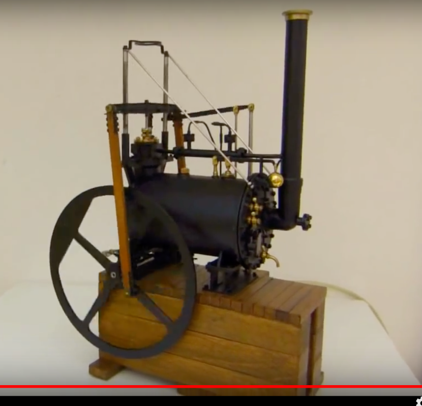
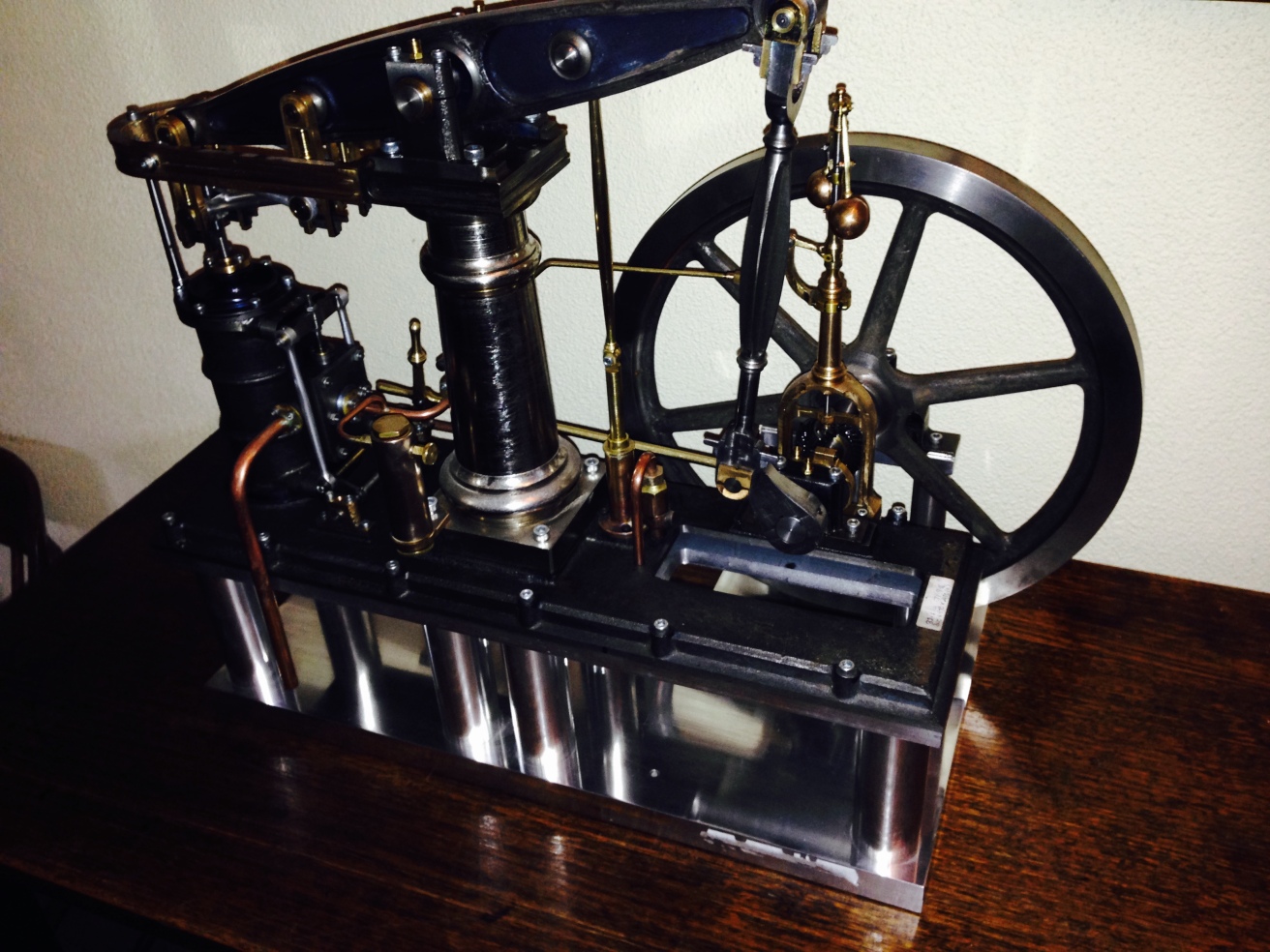
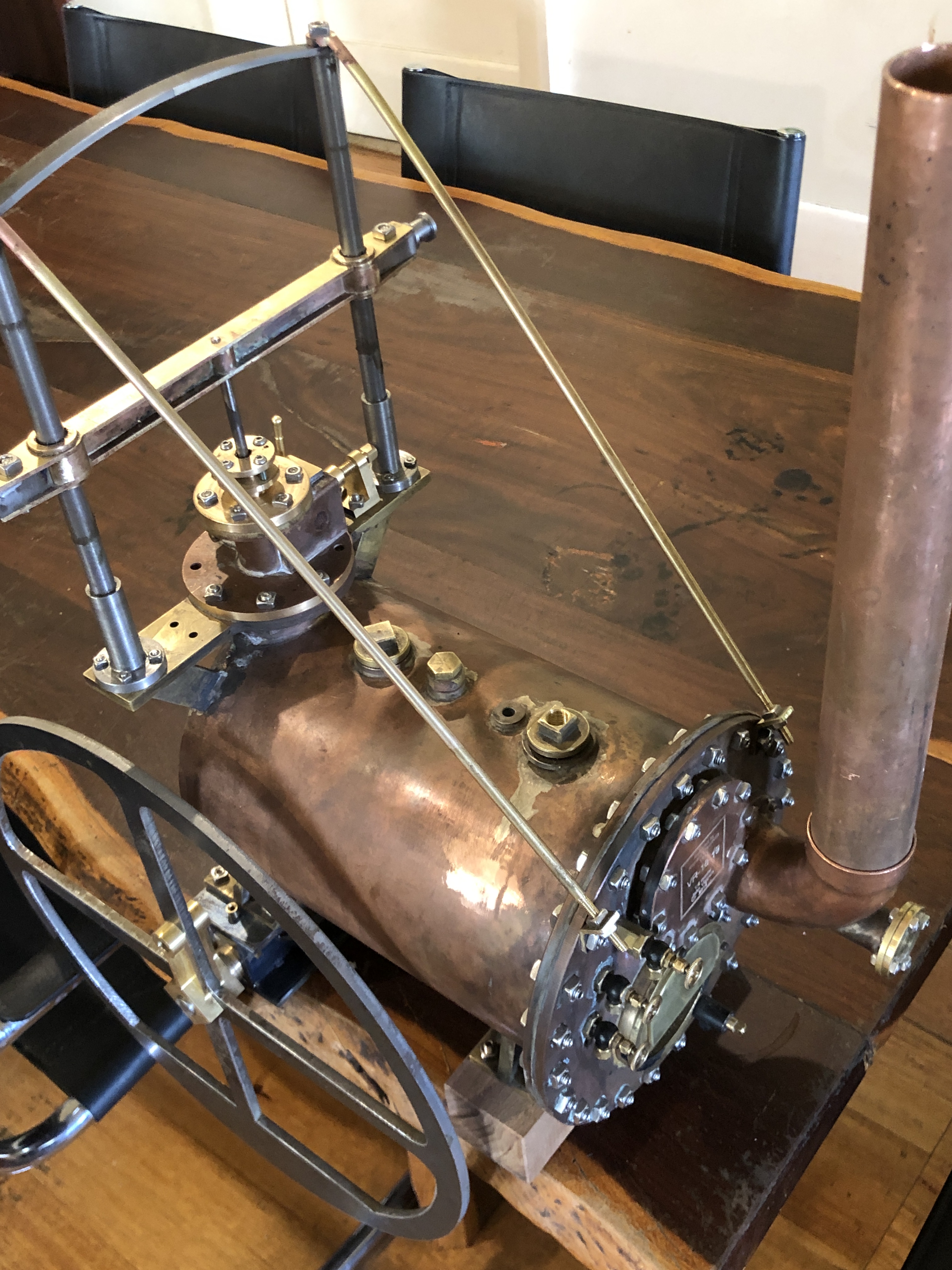
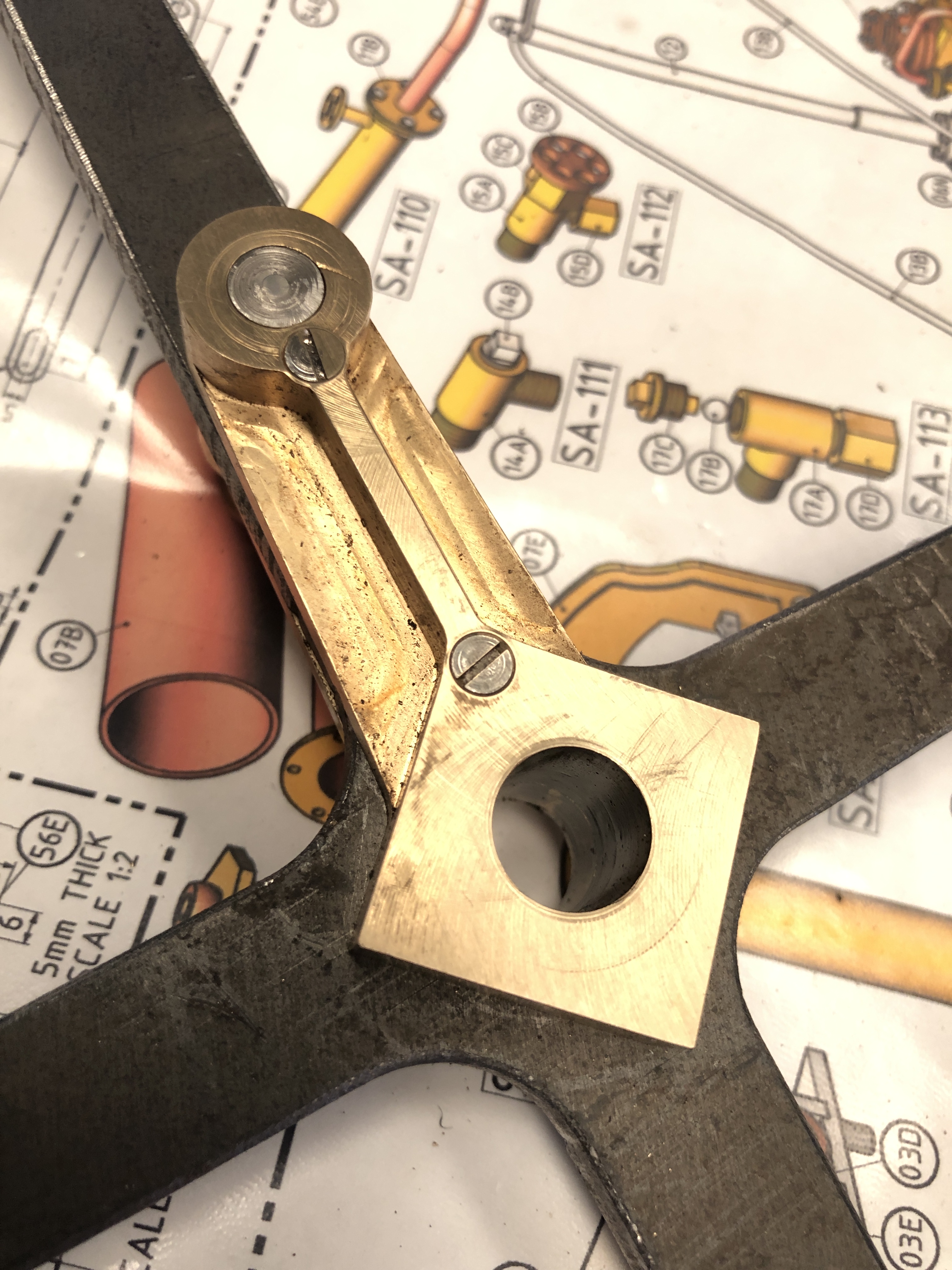
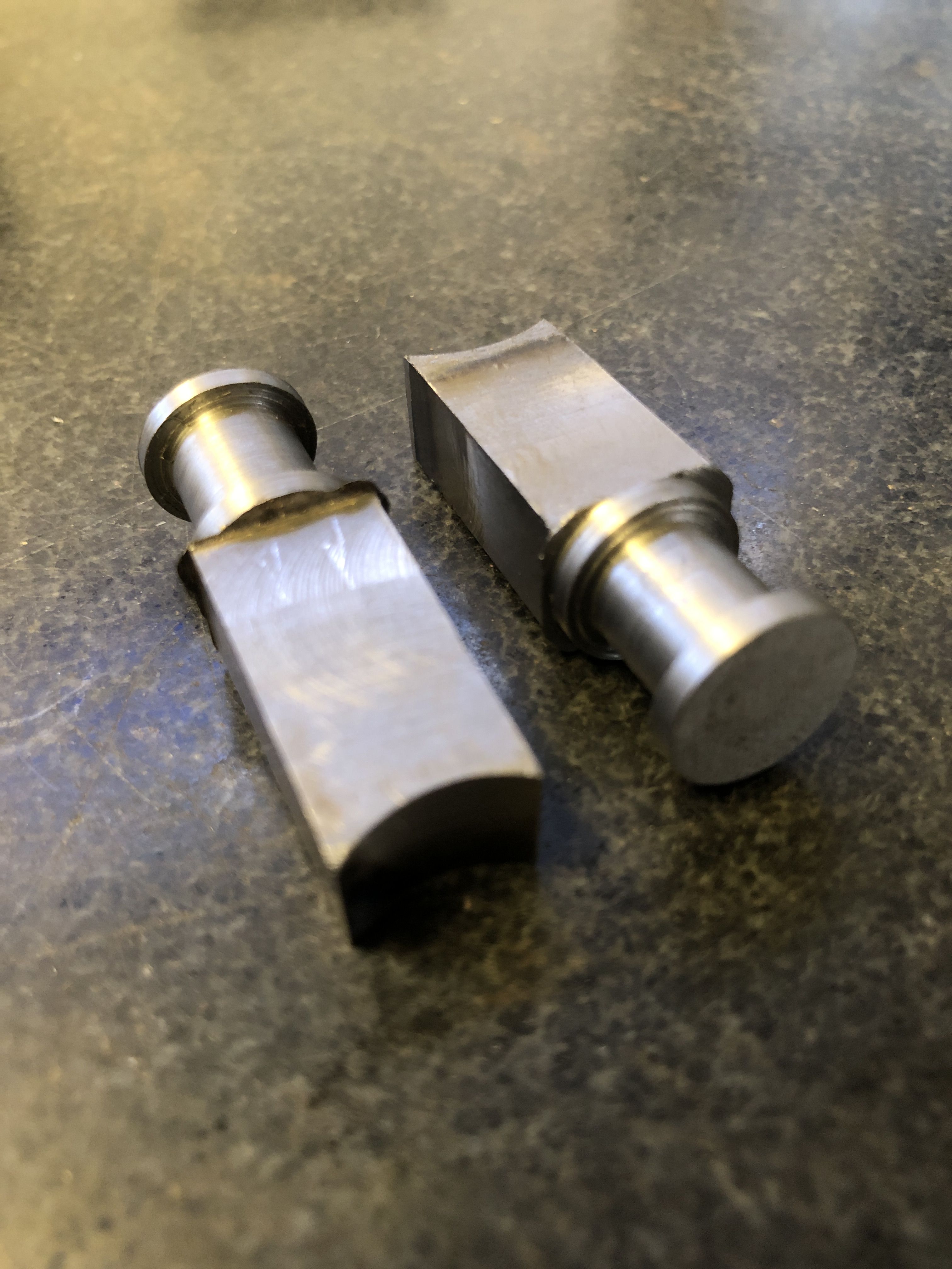
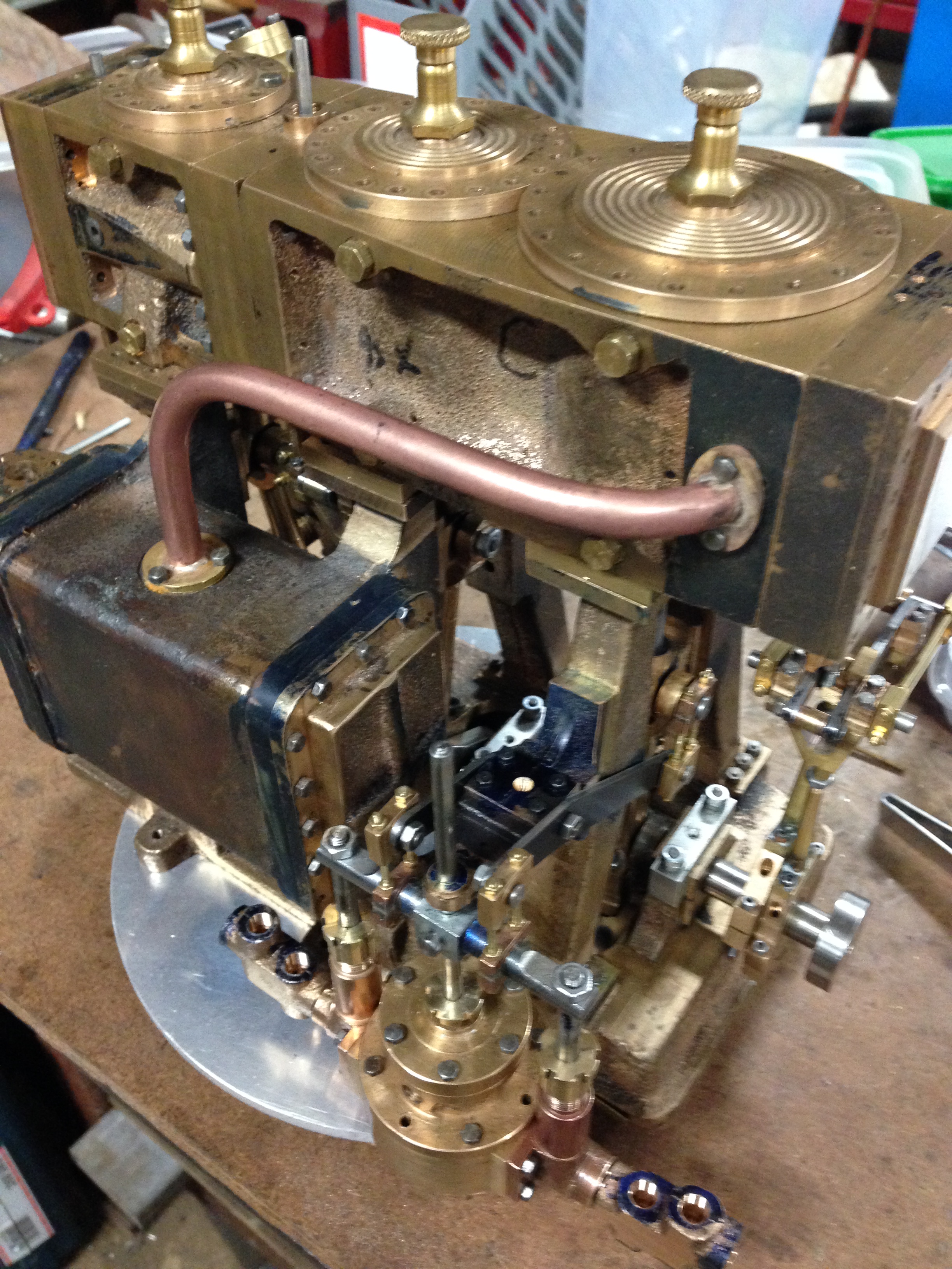
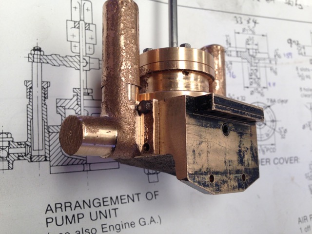
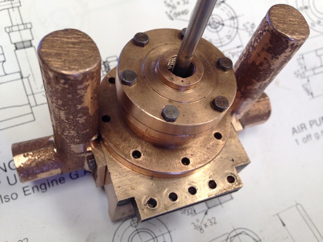
Yesterday I showed my model engineering group GSMEE, the bare old crankshaft, and the milled and marked lump of steel from which I am gradually removing all steel which is not crankshaft, and turning it into hot, sharp tiger snake repellant, I mean swarf.

“why don’t you just fix the old one?” (I tried. Unsuccessfully)

“why don’t you TIG weld the joins in the old one?” (possible, but Nah! It would distort, and would require finish turning, and I would probably be unable to use the existing gears, eccentrics, and big ends).

“You are going to get a lot more swarf”. (Yep!)

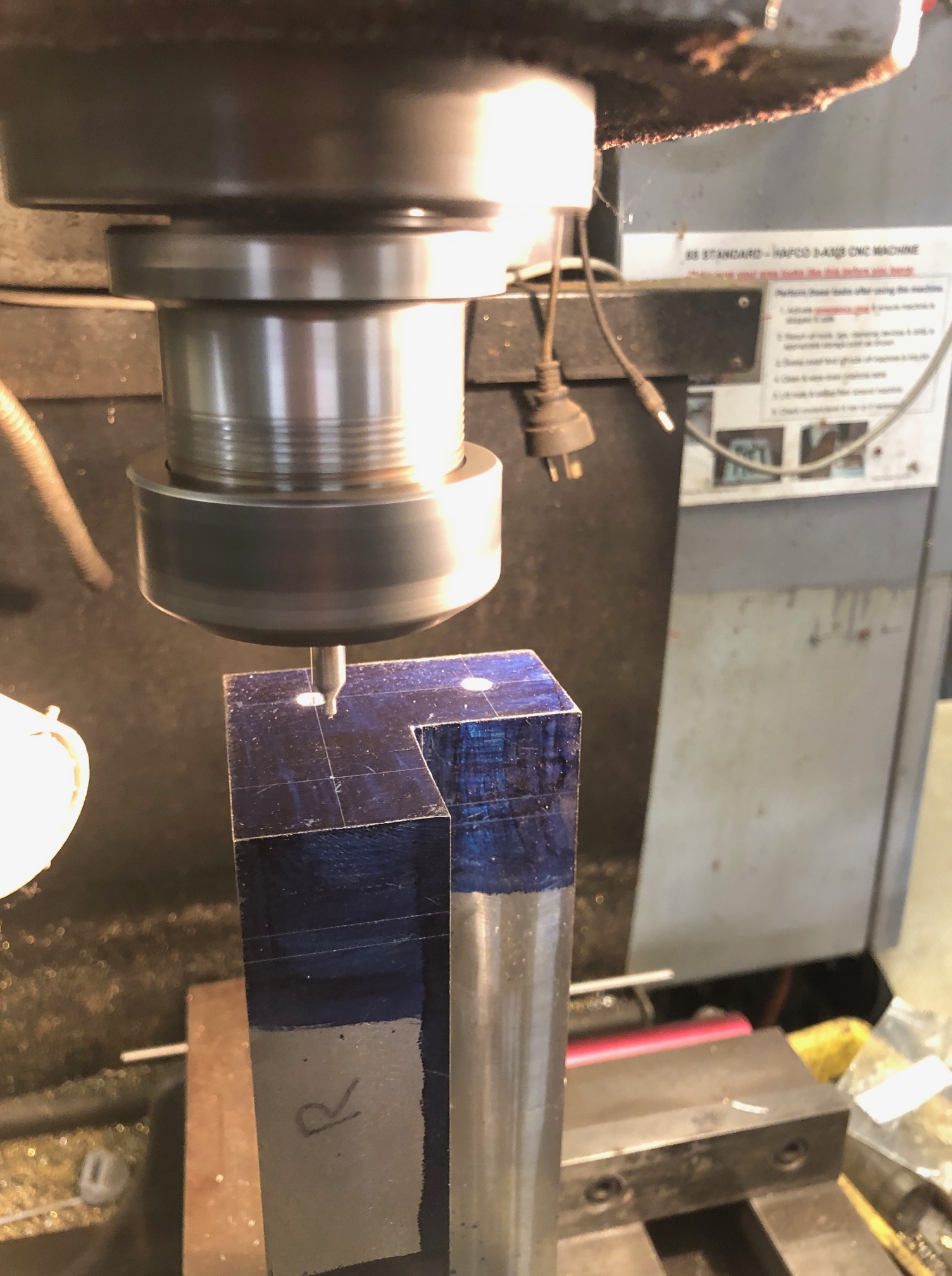
“What are the crosses for?” (So I know which bits to remove)

And some helpful suggestions….

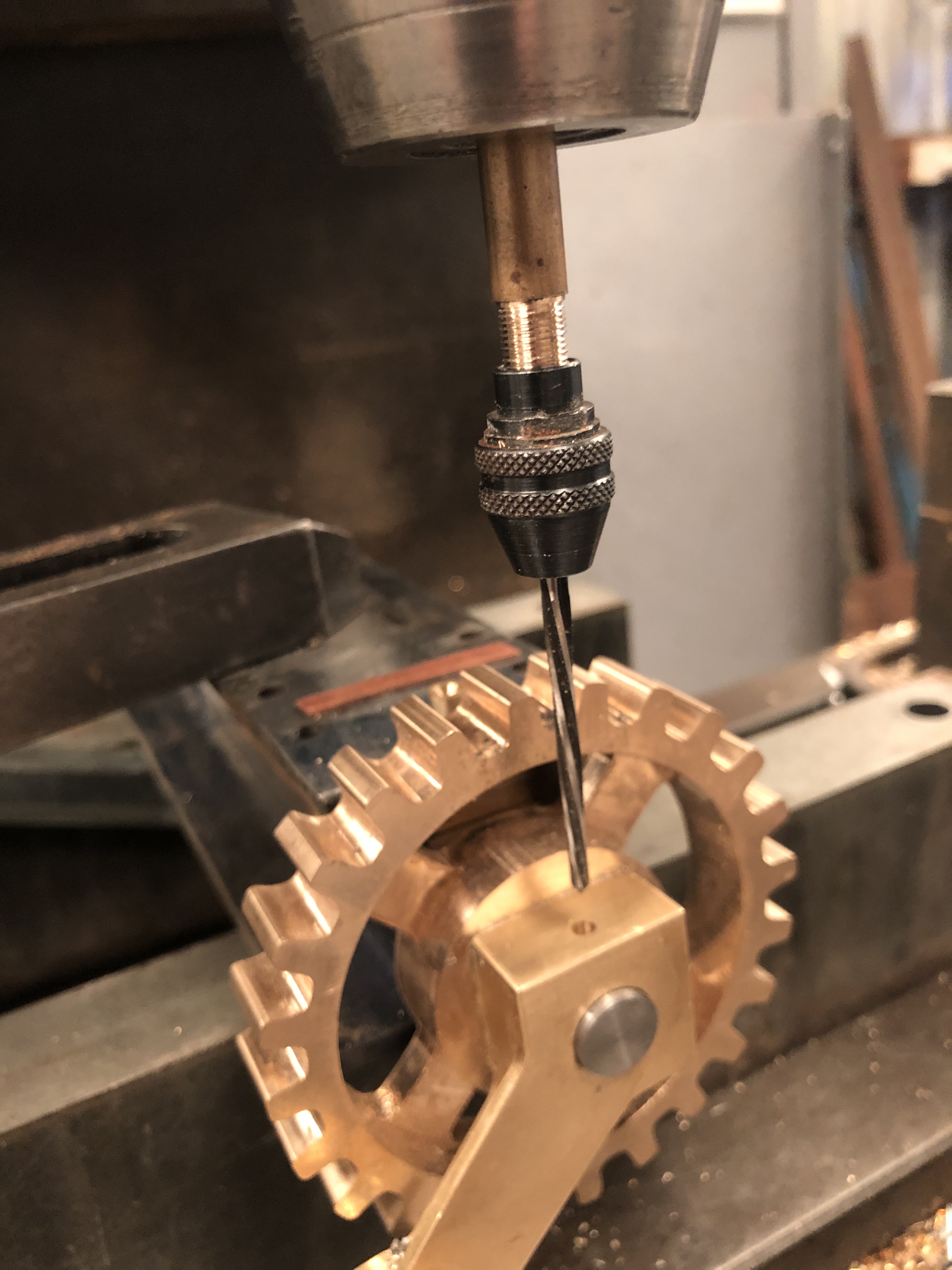
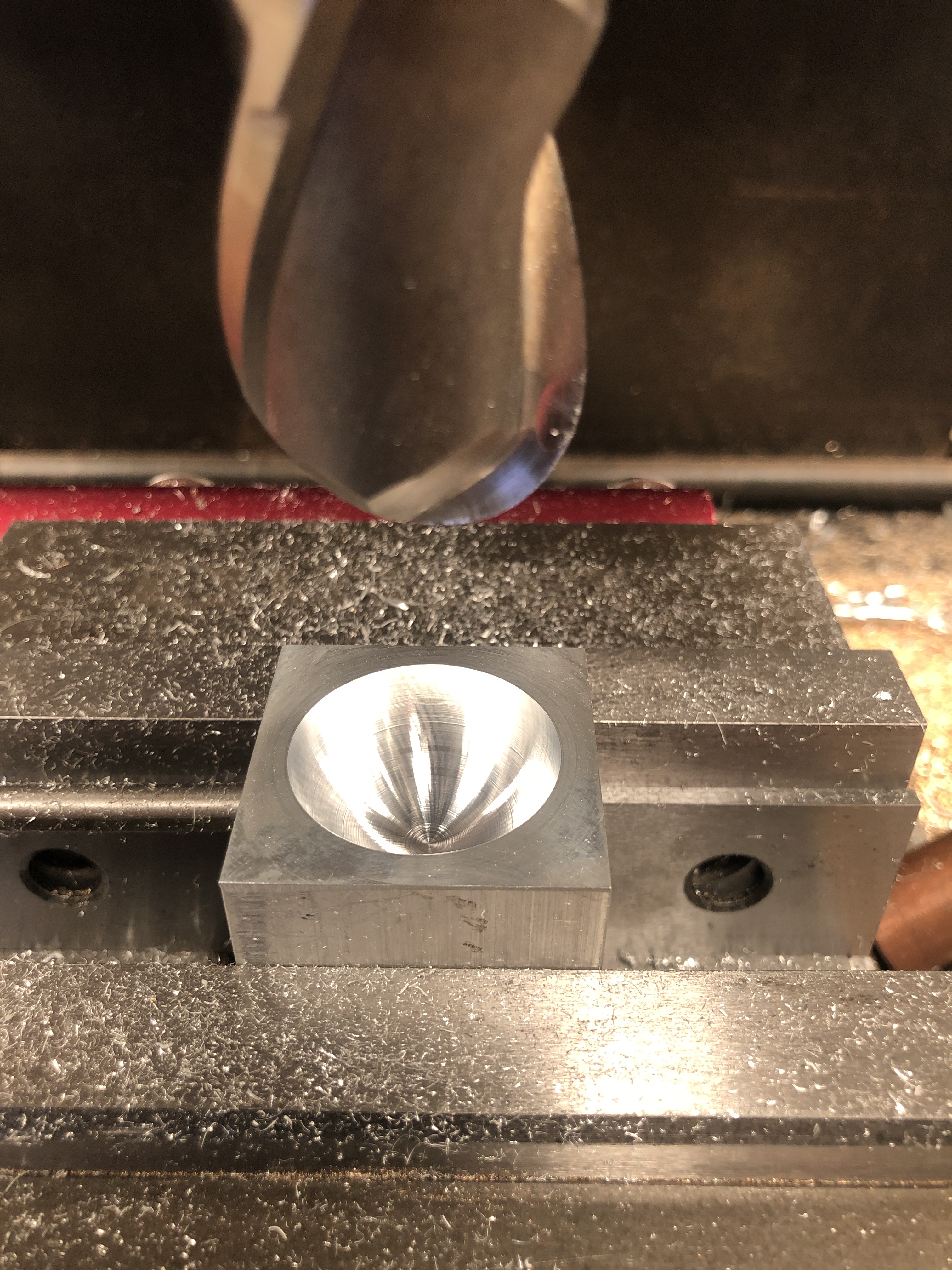
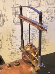
“Cramp the steel vertically on the CNC mill, and drill the centers using CNC movements” (yep!)

“Machine the journals a bit oversize, and re-machine the bronze bearings because they will be worn, and a bit oval” (yep!)

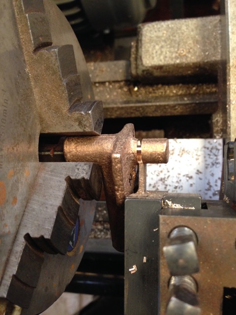
“Turn between centres. Use a solid tailstock centre, not a bearing type” (Yep!)

“Turn the journals toward the headstock, and reverse the workpiece to complete the other side” (yep!)

And, considerable skepticism that the job would be completed successfully. (Understandable. It IS a challenge. But so far so good).

Today another half day workshop session. About 5 hours.

First task was to center drill the turning centers for the mainshaft and the big end journals. I marked the positions on a surface plate, using a height gauge, but the actual drilling using a center drill bit was determined by cramping the workpiece to a large angle plate, establishing a master face, and using CNC to locate the drilling positions. I was pleased to note that the CNC positions lined up pretty precisely with my measured positions. Then turned over the workpiece, cramping the same face to the angle plate, re-established zero X and Y positions , and drilled the other end. Those center drilled holes will determine the axes for the mainshaft and big ends, which are the essential reference points.
Deeply drilled holes for some heavy, interrupted turning sessions.

But before the turning there is a substantial amount of steel to be removed by other means.

“Other means”.

First I tried milling, using sharp carbide end mills 12mm diameter. After I had broken 2 newish end mills, I thought about other means.

First, I used a bandsaw to make deep cuts. That steel is 38.1mm thick, and the cut is 38mm long. That is the thickest steel that I have ever cut with a bandsaw. I was REALLY surprised how quickly the cuts were made. Each one took 70-90 seconds.

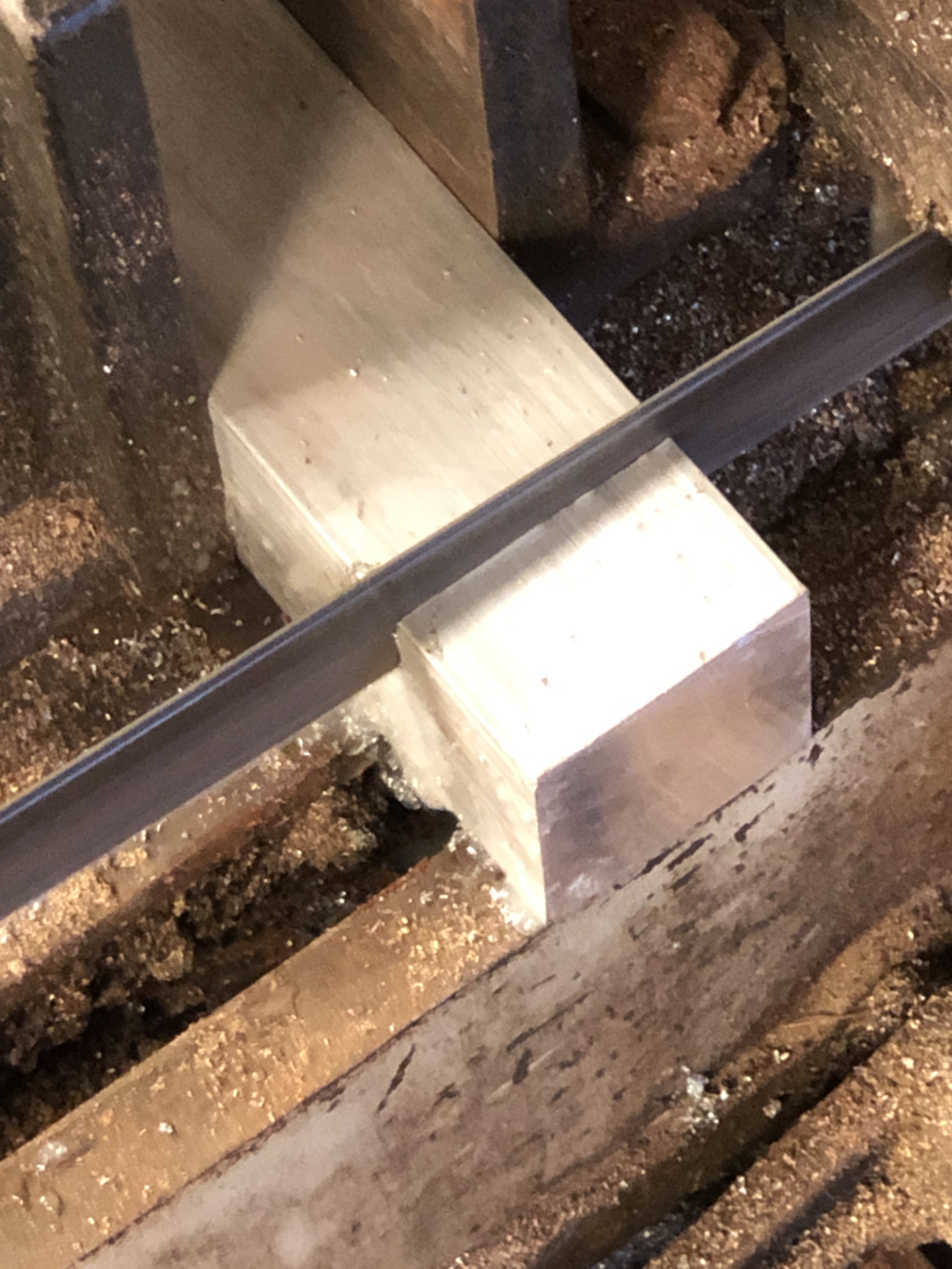
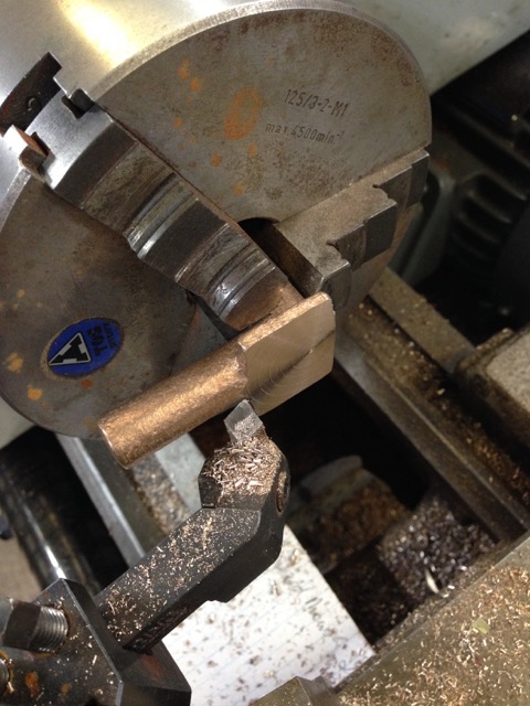
Then I thought about using the bandsaw to make the long cuts, up to 200mm long, through 38.1mm steel. But the bandsaw blade was 25.4mm wide, so I chose to make a milling slot 25.4mm wide to allow access of the bandsaw blade. In the process I broke a HSS then a solid carbide 12.7mm cutter. Expensive.

A bandsaw cut 200mm long, in 38.1mm thick steel. It took 7.5 minutes. Surprisingly quick and effective! But cutting the slot was problematic… broke two cutters.
So, for next one, I just used the bandsaw, making two angled cuts to remove 90% of the waste, then milling the hump out. That was easy. And quick! Way to go!.
After the tidy up milling. That is half of the debulking process. Another half to be done tomorrow. Already the lump of steel is a lot lighter. Currently 10.5kg. The old crankshaft weighs 3.3kg, so still a lot of material to be removed. Just a reminder that the original weight was 26.5kg!

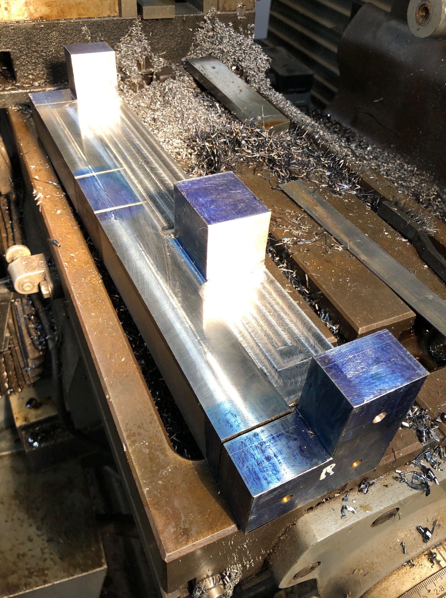
SO. I have formed an opinion about removing waste metal. BANDSAWING BEATS MILLING, HANDS DOWN! (but for finishing, milling wins.)

6″ Vertical Boiler, Triple Expansion Steam Engine and Southworth Pump, all working together. Fairly well.

2 videos of the triple and the vertical boiler and the Southworth boiler feed pump working together for the first time.  Not perfectly yet, but working.


Thinking about future exhibitions….

Still recovering from The Royal Geelong Show, where my beam engine and the Trevithick      dredger engine ran for ~8 hours per day for 4 days, and required almost constant supervision. I was very pleased that they did so without a problem.

For future exhibitions I would like to also run the triple expansion steam engine using the vertical boiler, for which I recently made the Southworth boiler feed pump.  And there are occasions where I might run the triple and the beam engine together from the vertical boiler.  That arrangement will occupy a fair bit of bench space, and in this post I am considering options for the arrangement.

But first, I needed a steam outlet manifold to handle multiple engines, simultaneously, and hopefully to avoid a big tangle of pipes.  Here is the manifold.

IMG_8246.JPG

The manifold has 6 x ¼” outlets and one 3/8″  outlet.    

Option one lines up the boiler and engine like this….

IMG_8243IMG_8244

Option two is more compact, but ?less appealing.  Pics following..

IMG_8237IMG_8238

IMG_8239

The lump of wood under the engine is temporary,  just to give an idea of the heights.

OK, this post is just an excuse to show some pics.  I have decided to go with option one.  It is closer to the appearance if the boiler and engine were actually in a boat, and also will make it easier to add the beam engine to the right of the boiler if/when I run the two engines simultaneously.

And I doubt that I will be able to avoid a jumble of pipework.  The triple has 6 pipes attached, the boiler has more, then there is the beam engine.  And, I will need a water container from which to feed the boiler.  That will be located behind the boiler.  Still considering whether it should be a squarish box on a stand like the railway water towers, or a cylinder on a low stand.   Any thoughts?


Royal Geelong Show 2019

The “Show” was held over the last 4 days.  I will not bang on again about my republican leanings.  See posts from previous years if that persuasion is of any interest.  The weather was ordinary.  Quite a few showers and blustery wind.  But we were mostly warm in the Vintage Machinery shed where our Model Machinery cage is located.  Fairly good visitor numbers, but not much real interest in our model engine offerings.

I exhibited my beam engine and Trevithick dredger engines, both running on piped steam.  The vertical boiler and feed pump was on static display, of no interest to anyone.  My Stirling engine got the most attention from kids, who are attracted by the swirling spiral colours, and not much interest in the intriguing method of running.  I am convinced that models must be moving, colourful, and have some relation to what people and kids see on television if they are to have any traction with the public.

But, the model and full size engine exhibitors enjoyed the displays, and an occasional visitor engaged in conversation.  Here are some pics and videos of some of the shed displays.  There dog shows, bird breeding, monster trucks,  horse riding events, cattle and sheep judging, and side show rides but these were not recorded by me.   I did visit the Amateur Astronomy display, and will visit the workshop of one of the exhibitors soon.

50 yrs vintage machinery.JPG

Beam with lagging.JPG

I had applied wooden lagging to the beam engine cylinder

Package boiler and Trevor.JPG

Steam for the engines is provided from this Package Boiler at 25psi.   Enough to turn them over.  Capable of much higher pressures.

Package boiler diag

cage bench north

Cage Bench North includes the Trevithick dredger model, the beam engine and the Stirling engine.

Cage bench south

Cage Bench South.  Swen Pettig’s prize winning flame gulper, and 1″ Minnie under construction.

Stuart swen

Stuart and Swen ?discussing engine repairs.

P1033007.JPG

Model Engineering first prize!

triple.JPG

And the full size triple expansion engine.  The Vintage Machinery boiler is being upgraded, so there was insufficient steam to run the triple.


Boiler Feed Pump Pumping

Yesterday I reseated the pump valves, reassembled the pump, then tested it on steam.

Most of the following video has the boiler at only 25psi, but I did run it off camera at up to 75psi.

After making the video I redirected the exhaust steam from the pump into the firebox.  It actually seemed to improve the gas flame, maybe by acting as a blower.  Not so sure about this being permanent though, because the exhaust steam contains oil from the displacement oiler, and I dont want that oil to be deposited in the firetubes.

I will make a water tank to supply boiler water.  Maybe the exhaust steam could be passed through a heat exchanger in the tank, so the boiler feed water is preheated.

(if the video is not showing, click on the https link below)


Back to the Trevithick Dredger Engine Model – the lagging.

The only surviving Trevithick dredger engine, in the London Science Museum, shows no signs of ever having been lagged.  I know this, because I examined it closely, recently, during my UK trip.

No lagging, no marks in the paintwork, which would indicate wooden lagging strips ever having been attached.

But, we know that Trevithick readily adopted ANY improvements to his designs, and lagging was appearing on engines at about the epoch of the dredger engine design. Plus, his engines were in use as late as mid 19th century, and lagging was well established as a normal feature by that time.

And, my model definitely needs some efficiency improvement.  Using a 40kW burner to power an engine of this size is ridiculous.   So I Have added some lagging.

P1032772.JPG

Equipment for applying lagging, from the left…   scroll saw, super glue (I used 6 tubes), strips of wood (in this case, Australian Jarrah, grinder for shaping, Dremel for shaping, good light, and the engine with some of the strips glued in place.

I used about 48 strips of wood with some spares.  These were cut and sanded in advance.  5mm x12mm x 130mm.

The Super glue is used to hold the wood strips in place temporarily, until the brass boiler bands are installed.

I started at the top, and worked my way down on both sides.  Most effort is made in fitting around  pipes and boiler bosses.  Unsatisfactory strips are levered off and scrapped.

P1032773.JPG

A rebate was milled on every wood strip, to permit removal or tightening of the boiler end plate nuts.

P1032774.JPG

I used rubber tree ties to maintain pressure until the glue dried, but in most cases I just applied finger pressure until the wood stuck fast.

P1032775.JPG

Some pipes and fittings necessitated grooves being made with round files.

Super glue does not provide a permanent bond to copper for some reason.  And it certainly will not survive the heat from steaming.  But it is fine for a quick and temporary bond.

P1032776.JPG

After making and applying the brass boiler bands (this was covered in the “6”vertical boiler” posts) I used olive oil to seal the wood.  See discussion which follows.

I chose olive oil to seal the grain openings of the jarrah.  I know from previous firings that the temperature of the boiler shell does not exceed 100ºc.  Olive oil will not smoke or flame until the temperature exceeds  200ºc, which is higher than any other common oil.  Also, as a failed olive farmer, I have plenty of old olive oil.   At worst, my engine steamings might smell like a fish and chip shop.  And refreshing the oily surface will be quick, cheap and easy.  And the olive oil will not form a skin which might peel or flake.  Anyway, this is “model and experimental” engineering.  If it does not work, I will make some new lagging, alright!.

And I took some more photos with my Panasonic Lumix 100-2 camera…….

P1032781.JPG

Still some more painting required to the end plate, and some fittings.

P1032808.JPG

That domed boiler end with the cylinder protrusion also needs some paint.  But the lagging looks good hey?

Even SWMBO has relented…  “It can go with the other engines”.  It will, when it is finished.  Still requires more painting.

Video of the gas burner which works

The first 6 minutes of the video  is getting up to 40psi.  Then a couple of minutes of the engine working.   Big file, so be patient.

At Last, a burner which does the job!

You are probably fed up with my burner trials.  I certainly was.

Fundamentally, I was trying to get enough heat into the Trevithick model dredger engine boiler, and just not managing it.  My boiler is a scaled down version of the original, in copper.  It takes a lot more heat than the 6″ vertical boiler which I made last year and I think that the reasons are…

  1.  The Trevithick design, although revolutionary for 1800 was and is a very simple, primitive, relatively inefficient design by later standards.   No water tubes and only one fire tube (the flue).
  2. The linear dimension is scaled down 1:8.  The surface areas (heat exchange surfaces) are scaled down 1:64.  The volumes, representing power output, are scaled down 1:512.  So the scale is a major factor.
  3. The firebox is 60mm diameter.  I had no success burning coal or wood, although I gave up on that one quickly after one attempt.
  4. Absence of lagging.  Reproductions of Trevithick’s engines have wooden lagging, but there was no indication of lagging on the LSM engine, or in the 1819 drawing.  I do intend to install wooden lagging, in fact I have cut and prepared the strips ready to install.

So my colleague Stuart suggested that I try his Sievert burner…

IMG_7794.JPG

This is a Sievert 2954.  Stuart tells me that at full blast it puts out over 40kW!   The ring is steel, machined to fit the firebox, and a close fit to prevent cold air being sucked around the edges.

IMG_7785.JPG

Fitted into the firebox.  It coped reasonably well with the back pressure at about 1/2 strength. 

This unit raised steam from 2500cc of cold water in 10 minutes, and got to 20psi in 14 minutes.  The target of 40psi was reached in 18 minutes.

At 40psi the safety valve operated, and despite continuing to pour in the heat, the pressure did not rise above 40psi.  So I am expecting that the boiler inspector will be happy with the safety valve.

I then ran the engine for 45 minutes, turning the boiler feed pump on and off to keep the boiler water level up.  All went well.  I have made a video of the event, but the upload failed last night, so I will try again later.

Next, to contact the boiler inspector for the final (I hope) inspection.


More Gas Burner Experimenting

First I tried the Sievert 2943.  I tried different gas settings, and different positions of the burner in the fire box.  I quickly discovered that an opening had to be present next to the supporting flange.  Despite that, steam was produced in 10 minutes, and 20psi was achieved in 15 minutes.  My aim is to obtain 40psi, and maintain 40psi during engine operation.

Unfortunately this burner does not work if there is any significant back pressure in the system.  Stuart has advised me to try the Sievert 2954 which he says will cope better with back pressure.  The Sievert 2954 has a similar appearance to the 2943, so I have not photographed it.

I have borrowed a Sievert 2954, but it needs some setting up, so I thought that meanwhile I would try a burner style which had been mentioned earlier.  It is a tube with multiple transverse slots.  Despite being constructed rather roughly and quickly, it produced a good hot flame.  Perhaps a bit small, but promising.

IMG_7775.JPG

If the next Sievert is not satisfactory I will come back to this style, and experiment with different slot numbers and sizes.

If you are becoming a bit bored with all of these gas burner experiments, I understand.  When the burner is finally sorted I will be delighted and relieved.

I have machined some wood to be used for lagging.  It is West Australian Jarrah.  A dark coloured wood which is often used for exterior flooring.  I will apply it to the boiler soon.


Next Project

The Trevithick dredger engine model is almost finished.  Currently applying some paint.  And getting it ready for the final boiler inspection.  I am guessing about 2 weeks.

I have chosen a spot in the house where it will sit, and will post a photo in due course.

A few people have been asking if I have decided what to make next.  In terms of a major build, the answer is no, I have not decided.  I have considered a few possibilities.  Those possibilities include a model of Stephenson’s “Rocket”, Trevithick’s “Catch Me Who Can” or “Pen-y-darren engine”, a Shand-Mason fire engine, or even another cannon.

What I will do, is to complete several unfinished projects, and if a major project becomes obvious, imperative, then anything is possible.

The unfinished projects include…

  1.  An Arduino controlled rotary table.  The mechanicals are made.  Just need to dive into the electronics.
  2. The Southworth steam powered boiler feed pump for the vertical boiler.
  3. The CNC controlled tool post milling attachment for the Boxford CNC lathe.
  4. Paint the Bolton beam engine.  Lag the cylinder.  Install a cylinder oiler.
  5. Finish the triple expansion model marine engine.  The lagging, the piston rings, the gaskets, the oiler and oil pipework, and painting.

Looking at that list, I really do not need to start another major project.

And sometimes it is nice to sit back, and enjoy the glow and satisfaction of previous projects.  It does sound rather self satisfied, no?  So here is a selection of videos, mostly first runs of newly completed projects.  Most are YouTube links, but one or two will run directly.

This was the first model steam engine which I made about 5-6 years ago.  It is a Bolton 7 single cylinder mill engine, and this was the first occasion I had run it on steam.  It was a very exciting moment, seeing it actually running on steam.

Next came the Bolton 12 Beam Engine.  Still a crowd favourite.  The beard was ordered off by SWMBO not long after this.

Then a couple of Stirling engines.  How they work is still a mystery to me.


Then the problematic, difficult triple expansion engine, which took 3 years and several extended breaks to get to the working stage.  Still not finished completely.  Stuart Tankard’s boiler.  Since then I made a vertical boiler.

And somewhere in there I made this little reversing engine for the club competition.  Alas, it failed in action.

And 3 cannons came out of left field.  They started as a CNC project, but then took on a consuming interest of their own.  About this time I saw the necessity of learning how to put together a video.  Still learning.

IMG_6859

The 6″ vertical boiler.

And finally the Trevithick dredger engine.  The historical aspects of this engine, the genius of Trevithick, the fact that the engine works…. has been marvellous.  The engine is looking quite different with some paint applied.  And the propane burner is significantly better than appears in this video.

So, if you are still with me after all of those videos, congratulations on your stamina.  It is  therapeutic to take stock sometimes, and to wonder about where making all of these engines is going.  It was not to any plan.  Still no plan.  Just enjoying the moments, the days.

Trevithick Dredger Engine. Almost There.

Firstly some pictures.


IMG_7660.JPG

IMG_7661.JPG

IMG_7662.JPG

So, I have reassembled the engine and the burner and the base.

Did you notice the base?

No?   Excellent.  That is the idea.  A nondescript matt black base which is barely noticed.

Yes?  OK,  well it must be OK.

Then a trial of the burner inside the firebox, using the changes which have evolved over the past few days.

During the video I am constantly changing the propane flow, and there is a clear “sweet spot” point where it looks really good, and feels very hot.  I have not yet tried to steam with it.

Oh Shit!

PART 1

I was drilling a hole in the end of the Trevithick burner today.  The burner was securely held in the vice, but the heat annealed brass was not as strong as the torque in the 6mm drill bit.

IMG_7651

After the initial self hatred at misjudging the situation, I thought …oh well, I will have to make another one.    Then I thought, …I wonder if I can repair it…..

I still have the wooden forms which I used to make the burner originally, so, roughly twisted the part back into shape.  It was pretty malleable still.  Then forced it into the wooden form.  And beat it into shape with the copper hammer.   This was looking promising.

IMG_7652


IMG_7653.JPG

Then forced in the other part of the form, and applied the 20 ton hydraulic press.

IMG_7655.jpg

The curved shape was pretty good, but there was still some twist.

IMG_7654.JPG

I still had to drill an 11.5mm hole, so this time I used the form, successfully.   Then removed the twist by hand after knocking out the form.

Tapped a 1/2″ x 26tpi thread, and assembled the burner.

IMG_7657.JPG

All beautiful again.  And now the burner tube is properly secured.   The bulge under my thumb was pushed straight.


PART 2

My reader/advisor Huib, suggested filling the tube with stainless steel scouring wool, in order to improve the flame.

I asked SWMBO, and was directed to the appropriate supplier.. the local supermarket.

IMG_7650.jpg

Bought 3 types of stainless steel scouring pads.  The finest grade was available only impregnated with soap.  I am not sure how soap burns, probably pretty well, but I do not need that added complication.  Fortunately it mostly came out when tapped.   All very inexpensive.

IMG_7636.JPG

Then I experimented with all 3 grades, various degrees of packing it in, and using various lengths.  I even tried mixing the different types of steel wool.  It cuts easily.  Eventually I decided the best way was to have a loose wad of the fine mesh in the first 1-2 cm of tube, then a very light piece of the fine mesh in the distal 10cm.

It has improved the flame;   there is no back lighting of the jet itself, and there is a more even flame along the length of the tube.   I think that I will be able to improve the flame further, but will wait until I can test it inside the boiler itself.  In the video the roaring of the flame drowns out my voice somewhat.  You will not miss much.    I am varying the gas control.

Error
This video doesn’t exist

So, sorry about the voice track.  The stainless steel stuff is interesting.  It is like swarf, but not sharp.  I wonder how they make it.  I imagine that it works in the gas-air tube by creating swirls and eddies, and better mixing the gas and air, without impeding the flow much.

Back in the workshop tomorrow.  A few connectors to make, check the feed pump, then make an appointment with The Boiler Inspector.

By the way.  The parcel opening post was apparently not very interesting, so I wont bother with that format again.  I am aware that my video technique was pretty ordinary, but I am not inspired to try that one again.  Pity.  I enjoyed making that one.


Experiments With Propane and Paint

The gas burner on the modelTrevithick dredger engine has been more problematic than anticipated.  In the absence of published information about gas jet sizes, air hole sizes and numbers, the effect of a ceramic cover, and firebox size and shape, I have resorted to trial and error.  Having read many of the comments on the subject in Model Engineering web sites, I can see that most other builders adopt the same approach.

I have lost count of the number of changes which I have tried.  These are the ones which I can remember.

  1. Burner surround made from brass, as per the blog on Feb 5,6 8.   Ceramic top.  Burner difficult to light, and only the end distal from the jet would light.
  2. Fitted a tube with about 40 2mm holes beneath the ceramic plate, to better distribute the gas-air mixture.  The entire ceramic plate lit up, but the heat output was poor, and the the time to boiler steaming was very slow at 25″.  Also the flame contained lots of yellow, indicating inadequate air.
  3. Drilled holes in the end of the burner surround, to increase the air flow.  Some improvement.
  4. Tried 3-4 different gas jets.  Problems with obtaining jets.  Lack of published info.  Different threads and jet body sizes.  Used the CNC lathe to recut some threads to fit the Primus jet enclosure.  (0.5mm pitch, 4.5mm diameter).  This was all trial and error.  Air is admitted through the 4 holes next to the jet, using a venturi effect, which relies on the velocity of the propane coming out of the jet.  Important factors are the diameter of the air holes, the number of the air holes, the velocity of the propane, and probably the diameter of the propane cone of gas.
  5. In order to further increase the supply of air, I drilled the air holes progressively from 4mm to 6.5mm.   6.5mm was the limit due to available metal.  In the video which follows, you will see the effect of reducing and increasing the number of air holes.
  6. Drilled an extra 20 holes in the distributor tube, but the flames from the initial 2mm holes were too big.  Then made another distributor tube, with 60 holes, about 1.5mm diameter.  Better size flames.  See the video.
  7. Each variation has been tried with and without the ceramic plate.  I have decided to not use the ceramic.  It seems to restrict the flow of gas-air mixture, and causes flames to shoot out backwards through the burner surround air holes, sometimes setting the jet alight.

Error
This video doesn’t exist

Concurrently while experimenting with the burner, I have been applying some paint.  SWMBO insists that I am a hopeless painter, but I think that it is going on OK.

Error
This video doesn’t exist


Trevithick Engine. Tweaking the gas burner. Winning?

Looking at yesterday’s photo, the yellow flame indicates inadequate air for the amount of gas going in.  The air holes at the gas jet level were already at maximum size, so I drilled some holes in the burner base itself.

IMG_7600

Yesterday’s photo.  Feeble flame.  Not enough air.   So I drilled holes in the burner end, next to the gas inlet.  (thanks for the suggestion Huib!).  Unfortunately, the improvement was minimal.  And gas flames shot out backwards towards the operator and gas jet.  A bit disconcerting.  And, I wondered, could the ceramic burner itself be restricting the flow?

So the next step was to remove the ceramic burner, and make changes to the spreader tube beneath.

The ceramic burner broke in pieces during the removal.  Possibly still useable.

But I thought, maybe I will see what the flame is like without the ceramic burner altogether.

And this is what the flame looked like…

Error
This video doesn’t exist

Now, that is more like it!  (you can see the holes which I drilled in the end of the burner to increase air intake)

Admittedly, the flame will change when the burner is back inside the boiler, but this is the most encouraging flame yet.  Minimal yellow.  The gas flow will need to be reduced.

Next session, I intend to experiment with the hole sizes and number and angles.  I do not expect to be using the ceramic insert in the final version.

Model Trevithick Dredger Engine on Steam. Fail. Well, maybe a bare pass.

Well, I was really not expecting this.

After all, the engine was running well on compressed air at 30psi, and the burner appeared to have a good flame.

And Stuart was coming to be involved with the big event.  So nothing could go wrong!

I set up the iphone on a tripod.  Checked the light.  Oiled the bearings and slides.  Filled the boiler.  It takes 2 litres of water.  And hooked up the propane.  when Stuart arrived I lit up the burner, and sat back to see how long it would take to raise steam.

Some steam leaks were expected, on this first steam run.  Leaks don’t show on compressed air, unless they are severe.  As the water heated up, some leaks appeared.  The water feed clack valve and the sight glass were bad.  The clack valve just needed some goo.  Later I disassembled the sight glass, and cleaned the valve, with some improvement, but more work needed.  Or a new sight glass valve.  A couple of other trivial leaks were easily fixed.

So we watched the clock, and checked the temperatures.  Ot took 20 minutes to start raising steam.  That is a bit slow.  Eventually it reached 20psi, but the pressure refused to go any higher, despite fiddling with the gas and air controls.

At 20psi, I opened the throttle and gave the flywheel a swing.  You can see the result.

After that, we let it cool down and fixed the clack valve leak.  The sight glass valve leak was looked at later, but could not be fixed simply.

IMG_7600.JPG

The burner flame.  A bit feeble.  A bit yellow.  And occasionally blown out by the cylinder exhaust gas puffing into the chimney.  Stuart says that I need to angle the cylinder exhaust gas upwards in the chimney.  Apparently Trevithick did not do that on the full size models, but perhaps he should have.

The burner was definitely not up to the job, so in this last video, it got some assistance.

It does go!   Just needs a few tweaks.  Lovely sound.

Moon

I know that this blog is titled “johnsmachines”, but I do get interested in “other stuff” too.

I came across this video on YouTube yesterday.  It runs for 4 hours.

The footage was shot by an amateur astronomer, through telescopes which anyone can buy.  A 9.5″ Celestron  reflector (Schmitt Cassegrain I think),  and an 80mm Orion refractor.

I used to be an amateur astronomer, and still retain an interest.  One of my worst decisions ever was to give away an Orion 10″ reflector about 10 years ago.

Anyway, back to the video.  It shows the surface of the moon, concentrating on some interesting areas.  Following are some screen shots.  It is titled “Live Moon Surface Observation”.  Worth a look.  Suggest jumping to 28minutes and watch maybe 5 minutes, zooming in and out.

Screen Shot 2019-02-20 at 6.53.00 am.png

80mm refractor.  Look at the protruberance in the top left crater.  Looks like a clenched fist.  That is really unusual.  Impact craters often have a central spike, and it is thought that the moon has had volcanic activity in previous aeons.  But there is no atmosphere to cause wind erosion, and no surface water.  Just traces of ice in the depths of craters at the poles.  So how could that shape have arisen?   And look at the bottom right crater…. that rectilinear shape.   Circular shapes are meteor impacts, in many case impacts upon impacts.  So how do you explain straight lines like these?

Screen Shot 2019-02-20 at 6.39.51 am.png

The same craters through the reflector scope.  Image reversed.   Look closely at the areas surrounding the craters.  Do you see the other rectangular and square shapes?

Screen Shot 2019-02-19 at 7.35.54 am.png

Close up of the fist.  Pixellation appearing.

Screen Shot 2019-02-19 at 7.42.50 am.png

Enter a caption

Earth’s moon is strange.

It is the largest moon in the solar system relative to the parent planet.

It is much less dense than earth. (why? if it is made of the same rock).  (5.51g/cm vs 3.34g/cm.  Thought to be due to Earth’s metal core.)

It almost exactly blocks the disk of the sun during a lunar eclipse.  Coincidence?

The other side of the moon always faces away from earth.  Until the space program, no human had ever seen the other side of the moon.  The other side, incidentally, is quite different from the side which we see.  Much more cratered, no large flat areas.  Presumably most meteors come from the direction away from the sun (because they are scooped up by the gravitational field of the sun).

One moon day is exactly the same length as a lunar month.  It is the only moon in the solar system where this applies.  That is why the other side of the moon always faces away from earth.  Another coincidence?  (correction.  Pluto – Charon also exhibit this behaviour, so it is not unique, just unusual.  Thought to be due to “tidal locking”- thanks Gene).

OK.  I know.  You came to this site to look at my machines, particularly the Trevithick dredger engine.   I am still fiddling with small details which are not very photogenic, but necessary before I run it on steam.  Currently hooking up the boiler feed pump.

IMG_7560

IMG_7561.JPG

I was intending to pull apart the pump to show you the components.  It is more complicated than the exterior shows.  Piston, O ring, 2 stainless steel balls, one spring.  I machined that 3 way junction box from a gas fitting, adding the delivery union to the top.   Nothing tested yet.  I hope that it works!


Sight Glass on the Trevithick Boiler

Not real happy about this one, but it is necessary if I am to run the dredger engine in public, at club meetings etc.

The original dredger engine had 3 taps to check on the boiler water levels,  like this.

IMG_7162

An earlier stage of construction, using taps to reveal the boiler water level.

Unfortunately that setup is unacceptable for boiler certification, so I have installed a sight glass using the same penetrations.

IMG_7556.JPG

The red colour does not help.  But when I run the engine on steam, this is what will be seen.   Functional, but nothing like the original.  If I use compressed air, or steam from an outside boiler (i.e. my burner not being used), I can reinstall the taps.

The sight glass is a bit short, but it should comply with the regulations.

I have spent another half day experimenting with different spring configurations, so that the safety valve releases at 40-50psi.  Eventually I decreased the coil pitch of the spring, and the valve now releases at 45-50psi.  That will do.

Trevithick Dredger Engine. The Dredger

I have no intention of modelling the dredger, but in making decisions about the engine base have gone back to the sources to find out about the gun ships.  These are referred to as “gun brig”, “bomb-ship”, “hulk of a dismasted ship”, in letters by Trevithick and others.

The first three of these dredgers were recorded by Trevithick as being 80, 120 tons and 300 tons.

Trevithick dredger on Thames - Rees

This diagram is probably of the dredger “Blazer”, with a 6hp Trevithick engine powering the bucket chain and winch. The cylinder diameter was 14.5″ and the stroke was 4′.  Trevithick recorded that his dredger would lift 100 tons of mud per hour.  Rock and gravel 180 tons per 6-8 hour tide.  It must have been impressive enough for him to obtain a contract to lift 500,000 tons per year from the bottom of the Thames at 6 pence per ton.   Other dredgers had Trevithick engines of up to 20hp. (ref. “The Life of Richard Trevithick” by Francis Trevithick 1872)


Screen Shot 2019-02-16 at 6.06.32 pm.png

Magnified view of the engine house on the dredger.  Note the relative sizes of the flywheel and the bucket chain driving gear.


And this is the diagram of a cross section of a bomb-vessel from a century before Trevithick.  It is mounting a 13″ bore mortar.  Note the massive supporting beams.  You can see why Trevithick chose this type of vessel to mount his steam engine and dredging machinery.  IMG_7452 2.JPG

A Tour of the Model Dredger Engine

Now that I have a tripod for my video camera (an iPhone), I have become a bit more enthusiastic about making videos.  Terrible standard of video compared with Joe Pieszczynski, and This Old Tony, and Stefan Gotteswinter, but maybe better than just text and photos.  I will be interested in your responses.

The Dredger Engine is still not quite fully made, but while I had the video set up for the spring making exercise yesterday, I added the following.   It is totally unscripted, and unedited, so there are errors.  “pressure valve” instead of “pressure gauge” for example.  Have fun counting the errors.   The final 30 seconds is me having difficulty turning off the camera!

Error
This video doesn’t exist


Historic Model Compromised?

I was attempting to model the Trevithick Dredger Engine as true as possible to the original.  But, I also wanted it to run, so the flywheel would spin and the crosshead move up and down and the unusual valve control lever flick up and down.

There are several problems with this approach.

  1. The 1 in 8 scale.  This is the biggest problem with making a model.  Since the scale applies only to linear dimensions (e.g. the boiler is 6″ diameter compared to 48″ for the original), surface areas are at a scale of 1 in 8×8 (1:64) and volumes and weights are at a scale of 1 in 8x8x8 (1:512).  So my little model weighs a few kilograms (not actually weighed it yet) compared to 4 -6 tons for the original.   It does mean that there is a safety advantage in scaling down, in terms of boiler explosion risk, despite the fact that the model will be run at roughly the same boiler pressure as the original (50 psi).
  2. Some components do not scale well.  For example, the square nuts.  To my eye, they look too big.  If I was to make another of this model, I would make the fasteners smaller.
  3. The requirement of the model actually running.  The original was fired with coal, or in some situations wood, and even dried animal dung (in Peru, look it up.  There was no coal and no trees in the silver mines area).  I have made my model so that it could run on coal, but to be honest, that is unlikely to happen.  So I have made a gas burner.  And that involves gas pipes and regulator valve, which are impossible to conceal, and detract, IMO, from the appearance.
  4. Boiler regulations.  I want to run the model at club exhibitions, which means that the boiler must be certified.  The boiler certification regulations make no special allowance for historic models, so several compromises have been made.  For example a pressure gauge has been installed, and the water level taps must be replaced by a glass sight tube.  Not a biggie I guess, but it all adds up.  I will keep a separate set of parts which can be used when it is displayed as a static model, which will be most of the time.
  5.  Is this a model dredger engine or a model factory or mine engine?  I still have not decided.  Hence the rather ambiguous base.  I do not intend to build a dredger or section of a dredger, or a factory or mine or parts thereof.  But I have to admit that the base which is appearing in the photos so far does not look “right”.  Still pondering that one.
  6. And finally the colours.  Although Trevithick was a brilliant engineer, he was no artist.  I doubt that beauty, or attractiveness of line, ever entered his thoughts when he was designing.  If his engines were painted, the colour was probably utilitarian black.  Not that we know.  I can find no reference to colour in any of the works about Trevithick and his engines.  And there is not a skerrick  of original paint on the original engine in the London Science Museum, as far as I know.  Later engines, in the Victorian era, were painted in gorgeous colours, and I am tempted to paint my model as if it were a Trevithick engine which was being used in the Victorian era.  That is not so silly.  It is known that Watt engines, and even Newcomen engines were still being made in the 19th century, and Francis Trevithick records that many of his father’s engines were in use in the mid 19th century.  That little subterfuge could also explain why my model has a pressure gauge and sight glass!

I had a full day in the workshop yesterday, so I had better front up and straighten those steps for SWMBO.   Actually, it will an interesting job.  I will use a 4WD high lift jack(s) under the house to free the steps, then use the Landcruiser winch with a snatch block to pull the concrete steps into position.  Might be worth a photo.  How the steps ended up out of position is a mystery.


Fitting the Boiler Feed Pump to the Trevithick Dredger Engine.

The feed pump is attached to the base, and since I had not decided on the final form of the base I had to leave the pump sitting all alone on my messy bench.

But I have now decided to proceed with a wooden base, made of 32x32mm hardwood beams, and a solid wooden top to which the engine and the feed pump are attached.

So today I attached the feed pump.  The engine itself is still just sitting, not attached.  And the bits of the base are still a loose pile of beams of wood, not bolted glued or screwed together.

One minor problem was that there were incomplete dimensions on the plans for the feed pump and its supporting column.   Fair enough.  I assumed that the dimensions would be measured on the job.

First I had to make the steel beam which attaches to the cross head, and the column at the other end, and the pump… 3 attachment points.  I had cut out the beam last week, but it needed a couple of bends.   It was 4mm thick steel, so I did the bending in the workshop press.

IMG_7476.JPG

Bending the feed pump beam.

Of course one of the bends was too angular, so a bit of cold blacksmithing to flatten it.

And fitted everything to the engine sitting on the base.

IMG_7478.JPG

The holes which were drilled in the top of the base were a bit of a guess, because the distance between them was not on the plans.  I drilled them 28mm apart, but it was clear after assembly that they were too close together.

Then the penny dropped.  The holes in the base should be the same as the corresponding holes in the steel beam… 32mm.  so I filled one of the holes with epoxy filler, redrilled it, re-tapped it and reassembled everything.

IMG_7477.JPG

The re-drilled hole and filler are hidden beneath the feed pump.  The space in front of the boiler face is now occupied by gas piping and a gas control knob.  Not quite finished so no pics yet.  Notice the boiler pressure gauge on top of the boiler.  Not as per R Trevithick, because the Bourdon tube type pressure gauge was not invented until 1849, but it is required for boiler certification.   Maybe I will label this as a model of a Trevithick engine which was updated in 1850.

Next to make the pipe between the feed pump and the boiler feed pre-heater, and a bypass tube with valve.   I have not decided on the size or form of the water supply tank. A riveted squarish tank, or even a riveted cylinder would be nice.   Probably make do with a plastic bottle for the time being.

I also need to fasten together those base beams.  Have still not decided how to do that.

There are 4 types of wood in the base.  I might have mentioned one or two of them.  One is the top, one is the beam under the front of the boiler, the base beams is another, and there is a sizeable block underneath everything.  I doubt that anyone will be able to identify all of the wood types.  2 are Australian, one is European, and one is Asian (I cut up a breadboard for that one).

And thinking about a colour scheme.  Flat black is the favoured colour in most other models, but I want to include some Georgian reds blues greens or yellows.  And leave a bit of brass and copper for polishing.

Oh, and I made a ring for the top of the chimney.  Seen in the second pic.

Trevithick Dredger Engine Burner

Reader Huib suggested that I would need to modify the gas burner for my model steam engine even before I had tried it.

He was absolutely correct.  The burner was difficult to light and keep going, unless I blocked off at least half of it. (see previous post).

So, today, I modified the burner along the lines suggested by Huib.

img_7463.jpg

I added this stainless steel tube with drilled holes to the bottom of the burner, underneath the fire clay burner.  It is wedged into position.

And this was the result.  The burner li up easily when gas was admitted.

img_7461.jpg

From above you can see that the fireclay burner is red hot over most of its surface.  And hottest at the end which is deep inside the boiler.

I measured the temperature of the burner, and it was 790ºc.  I think that it will do nicely. After that, I sealed the fire clay burner into the brass container with a high temperature boiler sealant.

Yesterday I received in the mail a tiny pressure gauge.  3/4″ diameter, 0-80psi.  from EJ Winter, Sydney.  Order was placed Wed, arrived Thurs.  Great service.  Thanks Ben deGabriel.

Trevithick would not have had a pressure gauge in 1803, but modern boiler regs insist on one, so I have bowed to the inevitable, and will install this gauge on top of the boiler.  Photos to follow.   I expect to be running the engine on steam next time I am in the workshop.   WooHoo!   Not tomorrow though.  Baby sitting.


Trevithick Boiler Feed Pump, and a base.

Quite a few potential workshop days are being foregone because we in southern Oz are experiencing a very hot summer.  And the few more moderate temperature days are “lost” to essential jobs for SWMBO, and around the house.   Shouldn’t complain about the weather.   Townsville, Queensland, where my brother and family lives, has been declared a disaster area due to torrential floods…  1000mm (39″) rain in the last few days, with more on the way.  And the next ice age has apparently started in USA.

But,  back to the workshop for a few hours here and there, I have made the boiler water feed pump for the Trevithick dredger engine.   As usual, I grossly underestimated the time these few simple components would take to make.

IMG_7413.JPG

The pump is driven off the crossbar where the stroke is 100mm (4″).  At the pump, the stroke is ~17mm (~5/8″).  The suction side has an 8mm (stainless steel) non return ball valve and the delivery has a 6mm non return SS ball valve.  The plans specified a dummy pump, for appearance only, but I have made it functional.

IMG_7417.JPG

The 2mm ss cap screw is to limit the ball movement to 0.8mm travel.  Something less conspicuous will replace the cap screw.  Probably a ss grub screw.

The rod driving the pump piston is a piece of bronze brazing filler rod.  Just happened to be the correct diameter.

I will need to add a further pump, hidden somewhere, for boiler approval.  It will probably be a hand pump.

The next step is to design and make the stand for the engine.  The plans specify a large, and in my opinion –  ugly, wooden box.  So that is not on my option list.

Most of these “dredger” engines were used in factories and mills.  Some were used to drive mine pumps, and a few were used on dredgers.  In the factories and mills they would have sat on masonry or wooden bases, and on the dredgers they would have sat on the very solid decks.  (the dredgers in some cases were converted gun ships, designed to mount large black powder cannons,  mortars or seige guns, so they were very solid!)

Now, some pictures of other dredger engine models, and the reconstructed full size one, and their bases.  I have numbered the pictures, and I would be interested in my readers opinion about which would best suit my model.  Please leave a comment.


B002617|10280908

1. The engine as mounted in The London Science Museum, on large wooden blocks.

Dredger1.jpg

2. A Model Dredger Engine on a masonry base.  I could do something similar, but I would used aerated concrete.

images-6

3. A very simple wooden base.

Screen Shot 2019-02-01 at 10.39.21 am.png

4. A beautifully crafted model on a cabinet maker’s base.  Acknowledgement to fredyfredy42.                                              I like the colour scheme too!

Screen Shot 2019-01-30 at 5.30.56 am.png

5. Another simple wood block base, reminiscent of the gun boat decking and frame.

odellen 2 137 (69).JPG

6. An elegant wooden base

fullsizeoutput_f29.jpeg

7. And finally, the modern, aluminium base for the beam engine which I made a few years ago.  I like it on the beam engine, but I doubt that it would look OK under the Trevithick.  The dredger engine is shorter, taller, and narrower.


Timing the Trevithick Dredger engine-4

Success!!

After the debacle of the valve sleeve rotating because I had not secured it, I secured it with a grub screw, and had another attempt at running the engine today.

But before that I shortened the valve lever blocks by 2-3mm.  I had noticed that air was entering the cylinder well before top and bottom dead centre.  Shortening the bars delayed the entry a bit.   Still a little bit before TDC and BDC, but watch the videos to see the result.


So, it is still not finished, and the timing will need some fine tuning.  But it works!   Phew..

It works in forward and reverse, depending on piston position when it starts, or if the flywheel is given a initial swing.

In the above videos the engine is not bolted to the box, and some of the noise is the cranks hitting the box.  The valve arm being hit by the striker is also contributing to the noise.

I will work on the gas burner next.


Trevithick Dredger.. attaching the flywheel and driving gear to the mainshaft.

The flywheel and driving gear both are attached to cranks which join the connecting rods to the mainshaft.  It is important that both cranks are attached with the same angularity.   Seems simple.  The cranks are identical.  But small taper holes, through brass and silver steel.

Drilling the 2 holes took most of the day.

Figuring the setup was the biggest challenge.

IMG_7329.JPG

This is the setup on the milling machine.  The mainshaft is cramped on parallels, and ends of the cranks are resting on smaller parallels.   The square sections of the cranks have been centered.

First problem was that the 2.5mm drill bits were not long enough for the chuck to clear the gear.   I did not have adequately small ER collets (would have required ER8’s), but I did have a Dremel chuck which was small enough.  But no spindle for the Dremel chuck.  The Dremel chuck has a really odd thread.  I measured it at 40tpi, and 7.05mm diameter.

So I made a spindle.   Thank goodness for CNC threading.

IMG_7331.JPG

The Dremel chuck and the shop made spindle.

IMG_7330.JPG

Dremel chucks are convenient, but they are not very accurate.  Fortunately, once the hole was centred, the drill bits and reamer seemed to follow the centred start.   Here I am about to ream the hole which has 3 steps   2.5mm, 2,8mm, and 3mm.   The shop made spindle is held in the milling machine drilling chuck.

I took the reaming very gently, not wanting any broken bits of high speed steel stuck in the workpiece…. and all was well.

IMG_7333.JPG

And here is the gear crank pinned to the mainshaft.

IMG_7334.JPG

And this is the setup for the flywheel end.   Fortunately, by good management or good luck, I was able to remove the flywheel, leaving half of the crank insitu, for drilling reaming and pinning.

IMG_7328.JPG

I spent some time assembling the cranks and testing the rotation movements.  It does rotate, but there is still some sticking on the guides, the cause of which I have not identified/isolated.

So I sat back and enjoyed one of my Xmas presents.   Ah!   Bliss!

Making a Lead Ball for the safety valve

The deWaal plans for the Trevithick Dredger Engine call for a 30mm diameter lead ball for the safety valve.

I considered substituting steel or brass, and turning the ball, but lead is almost 50% more dense than the other metals, and that could be detrimental to the functioning of the safety valve, so I worked out how to make the ball in lead.

I have previously cast lead balls 14mm diameter, but this is significantly bigger.  I did briefly consider making a plaster of Paris mould, but I could find no balls of the correct diameter for the POP mould, so I decided to mill the mould.

On rummaging through my big milling cutters, I discovered that I have a ball nose cutter, 31.75mm diameter.  It was part of a package of cutters which I had purchased years ago, and almost forgotten.  I had bought the cutters BY WEIGHT.  I think that I paid $US5 per pound, and I bought 20lb.  Mostly the cutters were resharpened end mills, but one of them was an unused 31.75mm ball nose.  Pretty close to perfect for this job!

IMG_7302.JPG

First I cut off two 25mm lengths of 40mm square solid alu bar.

IMG_7305.JPG

Then milled them pretty close to square and identical.

IMG_7308.JPG

Then used the 31.75mm end mill to make a hemisphere in each alu blank and drilled and tapped for a 5mm cap screw in each corner. 

IMG_7309.JPG

On the left is the mould, screwed together, with a hole drilled into the spherical cavity.  Here I am heating it in a frypan, ready to accept the molten lead, which is being prepared in the cast iron saucepan on the right.  I hasten to add that SWMBO knows nothing about this.  Those utensils are part of my workshop gear, and will never be used for human consumption.  SWMBO does not read this blog, so I am safe.  I hope.

IMG_7312.JPG

From my previous experience with lead castings, I have decided that the mould should be 250-300ºc so the lead will not solidify in the small entry hole, and also to minimise the formation of voids in the casting.

IMG_7313.JPG

Here is the molten lead after pouring.  It is still liquid.

IMG_7315.JPG

And after cooling and splitting the mould.  The hemispheres were not exactly aligned.

IMG_7319.JPG

And there was a big void.  I could have filled it.  But I decided that if I made the mould even hotter, it might work better, so I made another lead sphere.

IMG_7325.JPG

The next one, on the left, worked perfectly.  I heated the mould to 300ºc, and no voids at all.   I also reversed the bolting positions which removed the hemispherical misalignment. Drilled and tapped for the supporting ring.

IMG_7326.JPG

And here is the weight in its final position.   I dropped it, resulting in a Death Star indentation, which I kind of like.  A little bit of polishing will remove the latitude lines.

Only one part for the day’s work again.  But it was a LOT OF FUN!


How Many One Off Parts Can You Make Per Day?

Obviously it depends how many machining operations are required per part, but these days I find that one or two parts per day is about all that I can manage.  That includes deciding on then finding the material,  drawing up the part in CAD, mounting the material and the cutter(s), then machining and finishing time.

Take today for example.  My aim was make a steam pressure valve for the Trevithick Dredger Engine.   It consists of a lead ball weight 30mm diameter, a lever arm with a hook, a simple stand with a M6 male thread, a movement restrainer, and the seat and valve.  6 fairly simple parts.  I thought that I might get it all done in one day.

But at the end of the day, all that I had made was the arm, stand and restrainer.  3 simple parts.

IMG_7299.JPG

The pressure valve arm, stand and restrainer in place.

Admittedly the arm is stainless steel of unknown grade.  I broke 2  (4mm) cutters before I had slowed the milling feed rate to a snail’s pace 40mm/minute.  Machining time for that part was over an hour!  Then at least another hour of hand filing and finishing.

It is just as well that the worst day in the workshop is better than the best day of working!

And next will the interesting job of making the 30mm diameter lead ball weight.  Still thinking about that one.

Trevithick Dredger Engine.. the steam valve operator.

IMG_7268.JPG

I did not know what to name this assembly.  It attaches to the cross head, and pushes the handle of the steam valve up and down each revolution to admit and release steam from each end of the cylinder.

It uses the U shaped metal strip which I cut out and bent yesterday.   It is 230mm long, and I made it from brass, including the filler strips which actually contact with the valve lever.  I made the filler strips a few mm longer than necessary, so I can file them as necessary when the engine is timed.

Trevithick Dredger Engine.. the firedoor fittings. Or silver soldering tiny pieces.

Another day in the workshop.

Yesterday I  bolted the latch to the door.  But how to attach the catch to the surround, and the restraint to the door.  The plans call for tiny screws, but that method did not appeal.  I decided to silver solder them in place.  Silver solder is immensely strong, and does not require tapping and threading minute screws into position.  The problem with silver solder is that some parts of the firedoor are already silver soldered, and I did not want to risk undoing that previous solder.

So, I used a heat sink.

IMG_7260.JPG

The catch is held in position by pressure from the latch.  I did NOT want to melt the solder of the hinge, so I rested a sizeable block of brass on the hinge.  Pure copper would have been even better.  Then, as I was soldering the catch, any heat travelling toward the hinge would have been absorbed into the brass heat sink.

IMG_7261.JPG

A staged shot, after soldering the catch was finished.  I was careful to keep the flux just in the joint which was to be soldered, to avoid the solder running into other areas.

IMG_7262.JPG

A close up of the soldered catch.  The iphone camera is pretty good hey?  That catch is only 3mm wide.   A bit of filing and finishing needed.

IMG_7263.JPG

And the finished door.  Looks OK IMO.

The next job for today was to machine a strip of metal 6mm wide, 2mm thick and 600mm long.  I decided to make it from brass because I have a sheet of brass the correct thickness, and I was already thinking about the tight bend which was going to be required.

IMG_7265.JPG

So, I bandsawed a strip of brass from the sheet, about 50mm wide.  Then removed the milling vice and universal divider from the milling machine.  I am amazed at how those items are becoming heavier with age!    Then cramped the brass strip to the table and machined the sawn edge with a 6mm end mill which protruded into the milling table slot.  Fortunately I managed to not enlarge the T slot during this procedure.

IMG_7266.JPG

Then moved the brass strip, and indicated it parallel.  Then used the 6mm endmill to cut off the 6.5mm strip.  Probably not very efficient, but it worked, and the strip was correctly sized and dimensioned.

IMG_7267.JPG

Finally, annealed the middle of the strip, and bent it around a 5mm thick piece of steel, with a rounded edge.   This will become the fitting which operates the steam inlet/outlet valve.

Trevithick Dredger Engine ….Con Rods

I had previously bent the brass U pieces which hold the split bronze bearings to the wooden connecting rods.  I had also made the con rods and the bearings.  Today’s job was to fit them all together.

IMG_7180

Bending the U pieces on my shop made bender.

IMG_7182

And the Jarrah con rods.  The U pieces need to be shortened.

IMG_7250.JPG

With the bearing in place, measuring the amount of shortening required (approximately).

IMG_7251.JPG

Using an end mill to shorten the U piece arms.  Note the paper between the workpiece and the vice jaws.  That reduces the chance of the work moving.  How do I know?  Dont ask.

IMG_7254.JPG

The holes are carefully drilled M4 through the U piece and the wood.  Stainless steel square nuts on SS threaded rod.   Then the bearing was reamed again to the finish dimension.  I have yet to make the wedges which hold the pieces in position.

IMG_7257.JPG

The (almost) finished connecting rods.

IMG_7258.JPG

And a test installation on the engine.  A bit of workshop clutter to add to the atmosphere.

IMG_7259.JPG

And I had a bit of daylight on this beautiful summer day, so I made and installed the firedoor latch.

I am hopeful that I will have this engine running before I say goodbye as my subscription to WordPress finishes.  Not exactly sure when that will happen, so if I suddenly disappear, do a search on YouTube for the video of it running on steam.    Still a fair bit to do before that happens, but things are progressing!


More Trevithick, and Xmas

The last 20% of the build takes 80% of the time.  Someones law.  But SO true.

I should be Xmas shopping.  But frankly, buying stuff which costs money, is not wanted or appreciated, takes time, and should be donated to people who really need it….  irritates me.

At least the adults in my family have taken a sensible decision to randomly allocate one person to buy a present, for one person only, to a maximum amount.

But it does mean that the one present should be meaningful.

I decided on something that my allocated recipient might like.  A bit unusual.  Something they (he or she) would never normally buy, and should make an impression.  But there was a catch….  I had to drive to the shopping centre, park, find the shop, and buy.

So I looked up the shop on the computer, noted the address, drove there, parked, paid parking, walked several hundred meters, and could not find the shop.  Walked for about an hour.   The shop no longer exists.  It has closed and they have not changed the Internet info.  Bummer.

But at least I actually own one of the items.   It is a bit old.  Actually about 40 years.  But it is in good condition.  so I will wrap it and give it.  And hope that its aged condition is not  detrimental.

My allocated recipient is the au pair, from Italy, aged 19, who lives with and looks after some of my grandchildren.  She is a lovely girl, and I believe that she is really enjoying her stay in Australia, with my youngest daughter and her family.

The present is an Australian flag.  I hang it on out front gate every Australia Day.  I hope that she sees it as a compliment, and a memory of her stay in in Oz.

I will buy a replacement for myself.  It will probably be made in China, but so what?

So today I had a few hours in the workshop after wasting a half day in the shopping mall.

Preheater tube 2.JPG

And made and installed the water feed tube from the pre-heater to the boiler.  I had made the clack valve in my previous session.

Preheater tube.JPG

I find that it is actually quite tricky to make the bends in exactly the correct place, with exactly the correct angular bends, and to silver solder the flanges at the correct angles.   This one worked out well.   I usually bend a piece of aluminium wire to roughly the correct dimensions, on which to base my copper tube bends.

Finally, normally, I detest Christmas (actually it is Saturnalia, a pagan roman festival).  The commercialism, the waste on presents, the killing of turkeys, pigs, sea life.   It is all gross, and I hate it. Yes, I am a grinch.  Once, I just refused to take part in it, but the fall out was immense, and I am not strong enough to repeat that protest.  But this year, my adult children have made a decision which makes me immensely proud.  They have decided to limit adult presents to one per person, (the grandchildren still get heaps), and the meal will be vegetarian.  A step in an wonderful direction.


Trevithick Dredger Engine- the stays


IMG_7189.JPG

The stays appear simple but they took several hours to make and adjust.

When I arrived at my workshop today I discovered that someone had attempted to steal the Toyota Landcruiser tray which I leave parked there.   A window had been smashed, the doors were unlocked, and the cowling over the steering column had been removed and broken. (presumably in an attempt to access wires to start it.)  The driver’s door lock showed signs of being jemmied.   The ignition lock also showed signs of being forced.  The thief must have been an amateur, unable to get the vehicle started.

The police arrived soon after being telephoned.

Fortunately the vehicle is drivable, but repairs are required.  I am relieved that it was not actually stolen.  The police told me that these vehicles are in demand by thieves.  They are built like tanks, and useful in ram raid thefts.

So the dredger engine will be put aside while I install video cameras at my workshop.

(I have deleted a paragraph here.  It was written with exaggeration caused by anger.)

After the police left, I made and installed the stays which are visible in the photos.


IMG_7190.JPG


IMG_7191.JPG

The lower end of the stays attach to the boiler flat plate end.


Trevithick Dredger Engine Progress

First day of summer in southern Australia today.  And it was very warm and windy.  Keeping my eyes open for snakes, but none seen.

I was pondering how to attach the crankwebs to the flywheel.  I had decided that I would not silver solder them together, because the heat would likely distort the thin flywheel.  And pressing them was not feasible because I had machined them to a sliding fit.  Whatever method was used, I wanted it to be reversible i.e. future disassembly possible.  So, in the end, I used small brass screws which will not be visible when the engine is painted.


IMG_7187.JPG

countersunk brass screws holding the assembly together.


I made 2 more U shaped bearing retainers to fit on the ends of the connecting rods (same as shown in last post).

Then made 2 shafts which will be attached to the cross head bar, to join to the con rods.  These are made from silver steel.


IMG_7185.JPG

The concave end had a radius of 10mm.  Fortunately, I had a 20mm end mill which worked well to produce the curve.  A bit of finishing required for these parts.  I will probably run them for a while in my gemstone tumbler to knock off the sharp edges and polish them.


IMG_7186.JPG

They will be pinned in place at the ends of the cross head bar.


Trevithick Dredger Engine Guide Bars

I was discussing the guide bars with a very experienced modeller, and he finished with some advice….  “make them either very accurately, or very sloppy, otherwise you will have problems!”

The guide bars and cross-head

Well, I decided to shoot for “very accurately”.

I made the cross-head bar, and silver soldered it together.

All seemed good.  Just the guide bar bushes to be made and Loctited into position.  After a soak in sulphuric acid and tidy up.

So I made the bronze bushes, drilled them in the lathe to 9.5mm, then reamed them to 10mm.  Or so I thought.

But when I fitted them to the 10mm guide rails, they were very, very sloppy.   Checked the guide rail diameter… 9.99mm.  Checked the reamer 10.07mm!!  Chinese reamer.

So I searched my reamers and found 2 more.  Another Chinese one measured 10.04mm.  Another was a Sutton, made in Australia.  It measured 10.00mm.  I reamed a test piece, which fitted the guide posts perfectly.   So which reamer did I use?   Guess.

I made some more bushes and Loctited them to the cross-head.  Then drilled and reamed them, carefully, accurately.  This time the fit on the guide bars was snug, perfect.

Is there a point to be made here?  You better believe it.

Trevithick Dredger Engine. Making and brazing the boiler cylinder tube.

The boiler cylinder tube is the vertical cylinder which penetrates the boiler shell, and boiler end plate, and eventually houses the cylinder and piston within the boiler.

In the previous post I described cutting the hole which encloses the cylinder.

Today I made the cylinder, and brazed it in place.

IMG_6679

Reference lines accurately marked using machinists blue.

IMG_6678.JPG

It is 51mm diameter, and wall thickness 3.2mm.

IMG_6680.JPG

Bronze brazed into position.

And now that the brazing is completed I can cut the boiler tube to its final length.  This was left until all the brazing had been completed, in case there was a major stuff up and it had to be repeated.  That should be the last bronze brazing join on this engine.  I can return to the easier, and lower temperature silver brazed joins from on.  I must mention that working close to a workpiece which is close to 1000ºc, for 5-10 minutes at a stretch is fairly uncomfortable.  Now I know why the bronze brazing torch is a minimum of 450mm long.  Even so, I got skin burns from the metal buttons of my jacket when I touched them after a session.   A leather apron from now on.

IMG_6681.JPG

Measure twice, cut once.  Actually, I measured this 3 times.

IMG_6682.JPG

Cutting with the drop bandsaw.  Very slow feed rate so the blade does not grab this very soft copper.  This removed 3 of the remaining 4 unwanted holes.  Just one remains to be filled.

IMG_6683.JPG

Final length of the boiler.  All nicely square.


Trevithick Dredger Engine. Cutting through the domed end plate.

This was a part of the build which I was dreading.

I needed to cut a 50mm diameter hole through the boiler wrapper and the domed end plate, and the bronze join in order to insert the vertical cylinder which houses the cylinder, piston etc..

Trevithic JD_SciMus1

In this reconstructed Trevithick boiler, the vertical cylinder is visible.  

A series of photos is probably the best method of explaining the process…

IMG_6656.JPG

The boiler is held in a vise with extended jaws.  A wooden plug fills the cylinder so the vise does not squash the softened copper.  The 50mm hole saw is fine toothed, and run very slowly (250rpm), using hand feed also very slowly.  The copper is 3mm thick, doubled to 6mm at this stage, and with a middle layer of hard bronze.

IMG_6657.JPG

When the full depth of the hole saw was reached I cut a horizontal slit with an angle grinder and snapped the piece out.  Then resumed the hole saw cut.  The middle of the domed end was the least supported, and it flapped about a bit, despite its 3mm thickness.

IMG_6658.JPG

The wooden plug is visible.  2 more cuts to go.

IMG_6660.JPG

Some extra length of the shaft was required, so I switched to ER40 and ER25 collets to hold the hole saw.  Cut completed.

IMG_6661.JPG

The domed end was slightly distorted by the cutting, since the copper was annealed by the previous bronze brazing heat.  So I inserted the original wooden form, and hammered it into place to reshape the domed end.  Worked quite well.  The edges are a bit chewed rough, but since this join will also be bronze brazed, and therefore gap filled with bronze, it should not matter.  In fact I intend to chamfer the edges to create a V to fill with bronze.

IMG_6659.JPG

And with the 50mm cylinder in place it all looked nice and square.  The removed copper pieces sitting on the vise.

And….  thanks to Stuart T, my CNC mill is again in action.  Stuart identified the probable culprit component (a chip on a board for the encoder for the Z axis servo motor), made a new board for the new chip and installed it.  He was not confident that it would fix the problem, with the likelihood that a complete electronic rebuild of all electronic components would be needed.  But it worked!   Hooray!!   I feel like my right hand has been repaired.   Thanks Stuart.

Trevithick Dredger Engine- the flat end

Trevithicks_engine

The 6″ vertical boiler has had its first brazing session, and has been put aside while I wait for the boiler inspector to give the “go ahead” so I can proceed to the next brazing session.  I am told that the first braze is the most difficult.   The next braze is bigger, but the components are all on or near to the surface, and it is consequently more straightforward.

So, while waiting, I pulled out the Trevithick Dredger Engine, and decided to make the flat end plate and flange.  These are machined from LG2 bronze disks 13mm and 8.5mm thick.

bronze blanks

204mm diameter.

IMG_6575.JPG

An aluminium sacrificial plate was made and held in the milling vise.  The bronze disks were CNC drilled.

IMG_6576.JPG

The disk which will become the flange is tapped.

IMG_6595.JPG

The holes in the end plate were CNC’d on the mill, which died during the procedure.  The Z axis went crazy.  Fortunately I managed to hit the panic button and the end plate was not destroyed.   Currently Stuart & I are trying to determine the cause of the robot madness, but that looks like being a lengthy process.   The rebate being completed on the lathe in the pic would have been an easy CNC mill process, but the workpiece was quite thin to be held in the lathe chuck.

IMG_6597.JPG

Showing how the end plate was held in the lathe chuck, with double rare earth magnets holding the plate away from the chuck jaws permitting the tin workpiece to be turned.  A bit tricky, but went well.

IMG_6598.JPG

The flange on the left will eventually be brazed to the boiler shell.  The end plate on the right will be bolted to the flange. 

IMG_6599.JPG

The end plate and the flange mated together

IMG_6600.JPG

The big tube 65mm diameter will become the firebox,  the smaller one 38mm dia will be the firetube exhausting to the chimney.

IMG_6601.JPG

None of the tubes are yet cut to length, but starting to take form. 


6″ Vertical Boiler- Steam Outlet & Safety Valve Standard

Some more progress over the last 2 days.

IMG_6565.JPG

The chimney flare sitting in its intended position.  The attachments at the smokebox are completed.


IMG_6564.JPG

The smokebox tube plate, waiting for its firetubes.  The bronze fittings are the safety valve and its standard on the left, and the main steam outlet standard on the right, sitting in position.

IMG_6563.JPG

My workbench becomes increasingly cluttered as a job progresses.

Silver brazing is the next step.  There will be 2 major soldering sessions, with boiler inspections after each one.  I will enlist some extra hands and expertise for the soldering.  (Stuart, I hope that you are reading this.)

Trevithick Dredger Engine Flywheel

You must forgive me for rushing this blog.  I do feel rather pleased to have made a start on the Trevithick Dredger Engine.

The first part for the TDE was waterjet cut from 6mm mild steel.  I emailed the DXF drawing Tues, it was cut out Wed and picked up today.  Impressive service from Colin and Sandy at Waterjet Geelong.    340mm diameter.  The finish of the cut is so good that some light filing and rounding the sharp edges is all that will be required.  I will machine the bore hole after the shaft is made.  The magazine article is my workshop copy.  It will not remain this pristine for long.

flywheel flat.JPG

flywheel edge.JPG

The thinness of the flywheel is a Trevithick characteristic.

The OTHER NEXT PROJECT

In the previous post I showed the boiler which I am intending to build.

In this post I will show you the steam engine which I also intend to build when I have AMBSC approval and I have accumulated the materials.  I have discussed the plans with the boiler inspector, and am in the process of redrawing the plans taking into account the required modifications so it can be run at public exhibitions.

It is the TREVITHICK DREDGER ENGINE, at 1 in 8 scale.

This was designed by Richard Trevithick, and made in 1806,   It was the first high pressure steam engine.  It also employed a steam blower, cylindrical boiler, safety valve, and many other innovations.  Incredibly, the engine worked in its first iteration.   Richard Trevithick was indeed a genius, although relatively unrecognised in his own lifetime, and for almost 2 centuries since.

Here is the earliest drawing which I could locate of the dredger engine.

It is from an encyclopedia which was published in 1818.

trev_1


Trevithick_High_Pressure_Steam_Engine_-_Project_Gutenberg_eText_14041

This is a drawing of a Trevithick dredger engine which was reconstructed in 1885, with some errors, including the bent connecting rods..   Of particular interest is the piston-cylinder assembly which is partly encased by the boiler to minimise heat loss. The large, thin, flywheel is a characteristically Trevithick feature.

Trevithic JD_SciMus1

The Trevithick engine as reconstructed, and as it is displayed in the London Science Museum today.  The blacksmiths who formed the domed boiler end, pentrated by the cylinder assembly must have been incredibly skilled.  (ps.  note added 10/4/19.  The domed end was a casting which included the cylindrical sides, and the flange at the chimney end.  It was not forged by blacksmiths.)

The Trevithick Dredger Engine was drawn at 1:16 scale by Tubal Cain in 1987, and modelled by him. His plans were published in “Model Engineer” magazine.

It was redrawn by Julius Dewaal at 1:8 scale and published on the Internet in 2016.  The plans are currently freely available on Google Images, as 9 pages of A3 plans.  The plans are beautifully drawn, but require some modification to comply with current AMBSC regulations.  I am currently redrawing the Dewaal plans with the necessary modifications.  When they are approved I will detail the modifications.  A 1:8 scale the flywheel is 340mm diameter (13.4″).

Trevithicks_engine

A schematic drawing of the engine, as it was reconstructed.

So, watch this space.  Getting the plans finalised and the boiler approved will take some time, as well as gathering the materials.  From my preliminary discussions with the boiler inspector I will need to learn how to braze in bronze, and I will document that process.  Finding a supplier of phosphor bronze in the required sizes is proving difficult, and I might have to settle for the nicer to machine, but weaker, LG2 bronze.  If any reader knows of a supplier of cold rolled phosphor bronze sheet 200mm wide and 6-8mm thick, I would be delighted to hear about it.

Triple retrospective

This post is for reader Roy, who asked how the triple expansion engine columns and base and cylinder blocks were aligned, and also about joint sealants.

To be honest, I did not really remember the details, but the posts on or close to Feb 2015 include the following photos.  The aluminium plates were precisely machined keep the column faces exactly separated by the final width.  The plates were bolted to the columns, then to each other.   I lined up the join in the plates with the center of the main bearing housings in the base plate.

The longitudinal alignment with the cylinder bores was determined by the precise drilling in the tops of the columns, and the cylinder base covers.  And a little longitudinal movement in the crankshaft allowed for a few thou discepancy.

IMG_2495


And this is what I used to steam proof the joins.  I used no gaskets.  The Loctite 567.  It was recommended by an expert friend who uses it on full size steam engines (thanks Tom!).  The Loxeal 58.11 is also excellent but it sets very hard, and is very difficult to separate later.


FullSizeRender 17.jpg

BOILER FOR MODEL STEAM ENGINES

Now that the model triple expansion engine is working on steam, I feel able to put it aside, again, and move onto the next project.  The triple is not quite finished.  It needs cylinder lagging, control rods for the cylinder drain cocks, drain tubes for the cylinder drains, and an extra pump for the condenser cooling, and some paint, possibly.

It also needs a boiler.  I would like to exhibit the triple at club demonstrations and public exhibitions, but for that I need a boiler which is certified by our boiler safety authority.  So I intend to make a boiler to AMBSC code, and big enough for the triple or any other engines which I might make in the foreseeable future.

This is what I have in mind….

boiler assembly

This is a copper boiler with a 152mm (6″) diameter barrel, a superheater, gas or coal fueled, and firetubes (most not shown).  The plans call for a 5″ barrel, but I have been unable to find any suitable copper tube, and I have some 6″, so that is what will be used.  I am currently drawing up the plans.

The certification process here in Australia requires the following steps:

  1. Preliminary discussion with the boiler inspector (done)
  2. Submission of 2 sets of plans to the boiler inspector.  If acceptable, one set is signed off and stamped and returned.  The other set is held by the inspector.
  3. Inspection of the prepared components by the inspector prior to soldering/brazing/welding.
  4. Inspection of the firebox and tube assembly after soldering/brazing/welding.
  5. Inspection of the barrel and outer wrapper after soldering/brazing/welding.
  6. Testing the boiler after completion.  This involves a hydrostatic test, at double working pressure for 20 minutes, then a steam test at 10% above working pressure.

If it passes, the boiler is certified for 12 months, after which it must be retested.  If it passes the retest it is certified for 3 years.

The certification process is performed by volunteer inspectors attached to model engineering clubs, and is done at no cost.

However the materials for a boiler like this are quite costly.  I managed to obtain some  copper tube for the wrapper, and bought some copper plate for the firebox and boiler ends on Ebay.  Bronze for the bushes from a local bearing supplier (LG2), and firetube copper tube from local plumbing supplies.  All up, so far, is approaching $AUD1000.  And yet to be factored is the safety valve, various cocks, sight gauge, hand pump silver solder.  And I intend to make and fit a steam driven feeder pump, and possibly a steam injector.

If there is any interest in this project I will post progress notes and photos.  Let me know.

TRIPLE EXPANSION MODEL ENGINE- FIRST RUN (air)

This is a short video of the first run of the Bolton9 Model Triple Expansion Steam Engine, which I have been building on and off over the past 3 years.

The video is a bit shakey, because it is taken on my hand held phone while I am using he other hand to operate the controls.  I really did not expect the engine to work!

It runs a bit roughly, and is still quite tight, but settles down in the final few seconds.

It is not running very smoothly, because it is on air rather than steam, and because it is probably only powered on the high pressure cylinder, and maybe a bit on the intermediate, and not at all on the low pressure cylinder.

The next day it would not run.  Very frustrating.  I suspect that one of the eccentrics slipped on the crankshaft, and threw the timing out.  Not the easily accessible low or high pressure valve, but the intermediate one, which needs another teardown to get to it.

But Hey!  It will work.  I can see the light at the end of the tunnel.

One of my readers has requested a description of the triple engine timing procedure, so that will appear on this blog soon.  Unless you have a particular need for the timing info I suggest that you give that post a miss.

A Turntable for the Triple Expansion Engine.

I have not weighed the Bolton 9 triple expansion steam engine, but I would guess that it is 20-25lb.  (weighed it.  25.5lb)

Access to the various bolt on bits and pieces has become increasingly difficult and tricky, and involves frequent repositioning of the engine.

I removed the bolt on base and that has improved the situation a bit.

Then I had a brainwave, thought bubble, inspiration  whatever, and I tried a ball bearing turntable….   you know….. one of those Chinese restaurant middle of the table gadjets.

It is incredibly useful!

Here are some pics and a video showing it in place;  just a demo of the engine at its current (unfinished) stage.  I think that the turntable might  become a frequently used tool for heavier models.

triple apr7.JPG

The Bolton 9 on the turntable

triple water pump valve.JPG

And the latest additional bits…   non return valves on the water pumps.

Triple Expansion Steam Engine -The water pump

john and audrey - 5.jpg

The triple will not be finished by Xmas.  No chance of getting into the workshop while we are looking after 2 grandchildren.  So the new aiming completion date is Jan 6, in time to run the triple on steam at the Geelong truck show.   If I don’t meet that deadline, the next access to steam will be the end of 2017.  I really do not want to wait that long.

So the next component to produce out of a chunk of gunmetal is the water pump.

triple-expansion-engine-1-18

There are two cylinders in the water pump.  The gunmetal castings appear to be good quality.

Most of the machining will be done on the mill.  But I need a datum surface, and have decided that the attachment plate is the most appropriate.

triple expansion engine - 1 (20).jpg

I do not need the small cylindrical protruberance, but that chunk of gunmetal might be handy for something else (eg as a bushing), so I parted it off and saved it.  Lovely parting tool is from Eccentric Engineering.

triple-expansion-engine-1-17

Then turned a flat surface.  On the mill I machined it to a rectangle.   Diamond tool is also from Eccentric Engineering.

triple expansion engine - 1 (21).jpg

The two water pump cylinders are bolted to the air pump.  BA7.  A broken tap is entombed in the air pump forever.

triple-expansion-engine-1-22

When I get back into the workshop I will machine the rest of the pump parts.

Prize Winning Hit and Miss Engine

This Hit and miss engine by Stuart won first prize at the Royal Geelong Show Model Engineering section.

Second prize to yours truly.

Model Bolton Beam Engine.

Model Bolton Beam Engine.

Making a Stephenson’s Link for a triple expansion steam engine

Progress on the triple has slowed lately, partly because I am spending spare time on the Colchester lathe commissioning, but mainly because the plans for the Bolton 9 triple expansion steam engine are fairly vague and hard to interpret with respect to the Stephenson’s link reversing mechanism.  I think that I have finally got my brain around the workings of the mechanism, partly thanks to the many Youtube demonstrations, but mainly thanks to a series of articles in “Model Engineer” in 1985 -6, to which a colleague directed me. (thanks David).

The author of those articles has taken the trouble to document improvements to the original OB Bolton plans, and the improvements are much more comprehensible. (unlike this blog.)

My uncertainty was compounded by finding castings missing from the kit of parts which I had purchased.  I had taken the precaution of taking photographs of all of the castings when they were originally unwrapped, so I know that they were never there.  The supplier was not interested in rectifying the problem, so I am making the parts out of brass bar stock.

The following photos are the situation to date.

The eccentrics.  These are all split, and joined with M2 bolts.

The eccentrics. These are all split, and joined with M2 bolts.

The components of each eccentric.  The brass "halves", the bolts and the grub screw.

The components of each eccentric. The brass “halves”, the bolts and the grub screw.

The eccentric straps, also made in 2 pieces, joined with M2 bolts.  A groove is turned in each circle, and a corresponding ridge is turned in each eccentric.  All very precise and fiddly.

The eccentric straps, also made in 2 pieces, joined with M2 bolts. A groove is turned in each circle, and a corresponding ridge is turned in each eccentric. All very precise and fiddly.

Six valve rod "yokes" need to be made, but there was only one casting, so I have decided to make them all from bar stock.  The dimensioned bar stock (10x16x55mm) is seen here, with the "Model Engineer" article on the subject underneath.

Six valve rod “yokes” need to be made, but there was only one casting, so I have decided to make them all from bar stock. The dimensioned bar stock (10x16x55mm) is seen here, with the “Model Engineer” article on the subject underneath.

I will machine the yokes next week some time.   Space ships found in the Kazakhstan desert much more interesting, no?

Triple Eccentrics, 4th attempt success.

The eccentrics are turned from 2 bits of brass, which are separated later.  It was a trial and error effort, mainly error.

I tried soldering the parts initially, but mistakenly used silver solder.  All was well until I tried to melt the solder, and so much heat was required that the thin brass parts were wrecked.

Next time I used Loctite, but during turning, the parts flew apart and were again damaged.

Finally, I Loctited the parts, then bolted them with the final bolts, then turned the disks.  This method worked, but the 6 disks required almost perfect dimensioning on the milling machine during drilling, then the lathe for turning and parting.  Altogether, very demanding.

IMG_2945

Attempt one, showing the brass rod blanks which I soldered then turned, then separated, then discarded.

IMG_2951

Final run, showing the glued and bolted brass rod, and the turned and part parted disks

IMG_2954

Parting the disks was nerve racking, due the fine tolerances, and the eccentrically placed crankshaft hole. But it occirred without disaster

IMG_2958

Final cosmetic facing in an appropriately small Unimat hobby lathe.

IMG_2956

The finished eccentrics, stored on a piece of 10mm silver steel. There is less then 0.5mm between the bolt head and the machined edge.     Hooray!!!!

MODEL ENGINEERING EXHIBITION at BENDIGO, VICTORIA, AUSTRALIA

Bendigo is a beautiful city in the middle of Victoria, with a rich history, literally!

The city is in the “golden triangle” of Victoria, named for the huge quantities of gold which were mined from the area in the second half of the nineteenth century.

With that mining-engineering background, it is not too surprising that Bendigo has an enthusiastic and active metalworking, engineering, modelling club, and every two years they host an exhibition, which I attended for the first time last weekend.  And what a terrific event it was.   Well worth the 3 hours each way drive.

Following are some photos of a few of the hundreds of exhibits.  Please forgive me if I don’t remember some of the names and details.  The standard of the work varied from excellent to absolutely bloody unbelievable.

Welcoming visitors at the entrance, was Gerard Dean, with his 1/5 scale Tiger tank, powered by a V12 150cc engine.  Belching smoke, and overcoming any obstacles and visitors in its way.  There are a few of these models around the world, but very very few have a 12 cylinder gasoline engine which looks and sounds the part.  Gerard has taken his model to many countries, including the USA.  He does occasionally strike a hitch at customs, and usually has to prove that it will not fire real ammunition. The country which gave him the hardest time getting it over the border??  You guessed it…   Germany.

IMG_2904

The Germans were a bit upset that the engine valve covers are stamped “Made in Australia”.

IMG_2902 IMG_2903

IMG_2914

Inside, there were 2 large rooms,  with models, tools, books, kindred spirits who were delighted to have a chat.

Inside, there were 2 large rooms, with models, tools, books, kindred spirits who were delighted to have a chat.  I recognise the beam engine and quorn T&C grinder in the foreground.

Eccentric Engineering had a display of his Diamond Tool holder, but I have already bought 6-7 of these in different sizes.  I did top up my stock of Crobalt cutters.

Eccentric Engineering had a display of his Diamond Tool holder, but I have already bought 6-7 of these in different sizes. I did top up my stock of Crobalt cutters.

IMG_2911

Eccentric Engineering was showing his Acute Tool Sharpening System. I was very tempted to buy his kit of parts, but was fearful of my reception from SWMBO, if I returned with yet another tool and cutter grinder.

A very impressive Atkinson engine.   it was running earlier.  Les are you there?

A very impressive Atkinson engine. it was running earlier. Les are you there?

The Eccentric T&C cutter grinder kit.

Of the many outstanding models, this one was superb.  Not totally finished.  But totally appropriate for Bendigo. Of the many superb models on display, this one was outstanding. And totally appropriate for Bendigo, given its mining heritage.

IMG_2925

Pictured with the maker. The twin double acting steam engines were running on compressed air for the exhibition. Will look great running on steam!

IMG_2921 IMG_2922 IMG_2923 IMG_2924

Some future model engineers, viewing a very nice, running, triple expansion steam engine.

Some future model engineers, viewing a very nice, running, triple expansion steam engine.

IMG_2931 IMG_2932

A beautifully finished Bolton 12 beam engine

A beautifully finished Bolton 12 beam engine.  Makes mine look a bit drab.

10 cylinder radial aero engine, made from stainless steel.

10 cylinder radial aero engine, made from stainless steel by Bob Bryant.  Hmm, maybe a 9 cylinder.


I particularly likes this working Meccano model of an excavator.  The digging action was particularly realistic.

I particularly likes this working Meccano model of an excavator. The digging action was particularly realistic.

Another beam engine, this one made using Meccano.  Takes me back 55 years!

Another beam engine, this one made using Meccano. Takes me back 55 years!

IMG_2927

A particularly beautifully finished oscillating engine, totally made from bar stock.

IMG_2928

Triple Expansion Steam Engine Update, and some toy making

Some pictures following.

I have made the steam chest valves, the valve buckles, and the valve rods have been commenced.

The three steam chests, with valves and valve rods

The three steam chests, with valves and valve rods

The low pressure valve and buckle.  Steam chest behind.

The low pressure valve and buckle. Steam chest behind.  The machining on the buckle did not quite remove all of the casting roughness. 

And on a different subject, regarding last week’s post about making toys, this is the setup on my milling machine for CNC cutting of MDF.  I am using the new high speed head running at 20,000 rpm with a 2mm cutter.  There is a sheet of sacrificial MDF attached to the mill bed, and the material is attached to the sacrificial bed with double sided tape.  I hand held a vacuum cleaner nozzle to suck up most of the MDF dust, rather than breathing it, or having it settle on my machines and causing rust.

IMG_2843

CNC’ing MDF on an industrial scale machine.

The MDF after 20 minutes of CNCing.

The MDF after 20 minutes of CNCing.  This turned into a raptor.

Other People’s Triples

Click on the link to see a model triple expansion steam engine running on steam.

Cylinder valves for triple, and a neat method for cutting thin grooves.

The triple expansion steam engine now has a valve in each cylinder head.  They are manually controlled, not automatic, and I guess that is the reason they are called “false” valves.

The body of each valve was shaped in the CNC lathe, using software called “Ezilathe”.   There is a lot of good software for CNC milling machines, particularly Mach 3, but not much for lathes, at least for the non professional user.  “Ezilathe” is a free program (currently), works brilliantly, and was written by my friend Stuart.  It has an inbuilt simple CAD program, automatically generates G codes, and has a G code editor.   It also has a terrific, easy to use threading facility. It has an accurate simulator, and a tool editor.   Do a search on CNC Zone to download a copy.

The

The “false valves” in the cylinder heads.

One problem which I experienced with these valves was that the thread which secures the valves to the heads, stopped short of the expanded hexagon part by about 1mm, and I needed to turn a very narrow groove in the stem to allow the hexagon to screw down hard on the head.  I do not have a lathe narrow grooving tool with enough reach to do this, so the following photo shows how it was done…

A broken slitting blade, held in a shop made holder.  Normally I use it under power, but in this case, the part was held fairly tenuously, so I turned the lathe spindle by hand.  It worked perfectly!

A broken slitting blade, held in a shop made holder. Normally I use it under power, but in this case, the part was held fairly tenuously, so I turned the lathe spindle by hand. It worked perfectly!

Just for interest. This tiny engine was made by model engineer Peter B on a 3D printer.  It is about the size of a matchbox.

Just for interest.
This tiny engine was made by model engineer Peter B on a 3D printer. It is about the size of a matchbox.

TRIPLE BORING CYLINDERS

Today I bored the cylinders on the triple expansion engine.

Most model engineers would perform this task on a lathe, bolting the work to a faceplate or possibly using a large 4 independent jaw chuck.

The most accurate machine in my workshop is my CNC mill, so I decided to use the mill.

The setup is as depicted in the photo below.

IMG_2562

The cylinder boring setup.

IMG_2565

Cylinder boring complete. The setup took a couple of hours. The boring process also took 1-2 hours.

Of course, the high pressure cylinder needed to be center drilled, then drilled to 6, then 12, then 15mm, then bored to size 22.23mm.
Doing the job on the mill, I can be confident that the bores are all on the center line, all parallel, and the centers all correctly located. The intermediate cylinder finish was not acceptable, due to some chatter on the final cut, so I bored it out an extra millimeter to rectify the problem. The extra size will not matter. The piston (and rings?) will be made to fit the bore.

At the end of the session, I have left the setup intact, so I can check whether further processes can be performed using the same setup.

TRIPLE PROBLEM

Today I assembled the base, columns and Jig, intending to mill a flat top to the whole assembly.

To my surprise and dismay, it was apparent that one of the columns was one mm out of position.  Dont know how that happened.  A typo in the CAD drawing or CNC program?  It could not be a zeroing issue, because all 3 columns on that side would be out of position.

What to do?

I decided to turn the 2.5mm holes in the column base into slots 3.5mm long.  The bolting position on the jig was exactly correct, so I used that to zero the position, found a 2.5mm end mill, and gingerly milled the slot. holding the column upside down in the milling vice.

Fortunately, that seems to have worked.  The columns are now all correctly located.   The tops of the columns are the crucial plane and position, and they seem good.  I doubt that the slots will be an issue in the finished engine.  They are invisible under the column feet.  If necessary, I will make a couple of locating pins and drill them in position right through the base from underneath.  I doubt that will be required.

After that, I did take a milling skim off the column tops, to create a dead flat plane, to which to bolt the cylinder bases, when I have made them.

Not tomorrow though.  I am off to Ballarat Victoria to a swap meet on the aerodrome.  In previous years there have been approximately a thousand stalls.  Some are shed clean outs, some commercial vendors and dealers, and lots of ancient cars and machinery and parts.  The best stalls are the ones selling used tools.  I seem to come home after each meet with a heavy pack full of tools and materials, and a lighter wallet.  But it is always interesting and fun.

Triple progress

Today I made the BA7 studs for the columns on the triple expansion steam engine.  I decided to use 25mm bolts, then trim them to length after they were installed into the threaded holes.  Why not use threaded rod or make my own studs on the CNC lathe I hear you asking?  Well, I could have made my own studs.  In fact I did make 2 studs, quite succesfully.  But it was time consuming.  Cutting up threaded rod would have worked, but it turned out to be less expensive to buy over length bolts which are threaded right down to the heads, and trim them to length, than to buy threaded rod.  Plus, the trimmed bolts are now quite useable 12mm bolts.   Also, it was easy to use the bolt hex head to screw them into the threaded holes.

I did manage to break off one stud and spent a half hour or so digging the stub out and renewing the stud.  But no permanent damage.

IMG_2495

The BA7 25mm bolts are screwed into place, and held there with with a nut.  The saw blade was attached to a 200mm long arbor which was shop made for the job, shown here about to trim the bolts to length, on the milling machine.

IMG_2497

The studs are trimmed to length, and the columns are sitting in place, temporarily held with 4 nuts each. 9 studs and nuts is total overkill, over- engineering, but it looks the part, no?

IMG_2496

After fiddling with the minute BA 7 studs and nuts, trying not to go nutty myself, I had some fun rough machining the lump of brass which is to become the low and intermediate pressure cylinders.

MILLING THE COLUMNS for THE BOLTON 9 MARINE ENGINE

90% setup time, 10% machining.

The columns are tapered on all faces, so are difficult to hold, and difficult to measure.

I did a CAD drawing, to measure the taper angles, and to calculate some extra dimensions.

Then, in order to hold the castings in the milling vice, I made some accurate wedges at the appropriate angles (3 and 12 degrees) in wood and aluminium.

I actually progressed a bit further than the photos show, even roughing out the condensing tank.

IMG_2319

IMG_2317

The aluminium wedges have a 12 degree taper. The top wedge is sitting on a 10 degree and a 2 degree precision taper, giving an accurate 12 degree slope for milling. I made 2 such wedges, each 100mm long.

IMG_2318

Unmachined casting on right. Partly machined on left. Quite difficult to set up, despite the setp up blocks at the appropriate angles.

GSMEE EXHIBITION 2

Wimshurst Electrostatic Generator, made by Peter Bodman.  Creates sparks up to 100mm long, which drill minute holes in interposed paper sheets.  No-one volunteered to ry it with a hand.

Wimshurst Electrostatic Generator, made by Peter Bodman. Creates sparks up to 100mm long, which drill minute holes in interposed paper sheets. No-one volunteered to try it with their own hand.

IMG_2238

Vacuum engine made by Peter Bodman.

IMG_2263

Awesome model of pre-dreadnaught ship circa 1902 “Preussen” made by Walter. It is approx 1 meter long, weighs 16kg, and is radio controlled. The 28cm gun turrets are also radio controlled, but do not (as far as I know) actually fire.  To the right is a model of Columbus’s “Santa Maria”.

IMG_2264

The detail in the model has to be seen to be believed.  Every plank of the decking is individually made and fitted.

IMG_2284

Walter showed us the inside construction, engines, and electronics. The model was made from a few old photographs, and simple side and top elevations.

IMG_2285

Hull with the superstructure removed

IMG_2241

A very old pressure gauge, restored so that the workings are displayed, to reveal how it works. By Stuart.

IMG_2259

This model boat was made by 8 year old Niall, with some supervision from his Dad, William. The gun is actually a radio controlled water cannon which fires up to 3 meters, to the wet surprise of some spectators. Niall and William both had a fantastic experience with this project.

IMG_2262

William with some of the wonderful boat and ship models which he (and Niall) have made in recent years.

IMG_2249

A model working ship steam engine and boiler, by Walter. Twin cylinder, double acting cylinders. This should be jewellery, worn around the neck of a beautiful woman.  OK, that is a little over the top, but you get the idea


IMG_2250

Close up of the marine engine by Walter

IMG_2277

Les Madden with his partly completed Atkinson Differential Engine Model, originally patented in 1887. The wooden model on the left was built by Les in attempt to figure out how it worked! He made the wooden parts to have aluminium castings made.

IMG_2278

Les Madden’s Differential engine.

18 radial cylinder aero engine, by John Ramm.  The hand carved propeller is approx 600mm long.

18 radial cylinder aero engine, by John Ramm. The hand carved propeller is approx 600mm long.

IMG_2253

Detail of the aero engine. John showed 3 aero engines. He is currently making a 12 cylinder Spitfire Merlin engine which he will have finished by the time of the 2015 exhibition.

IMG_2281

Stuart Tankard’s prize winning hit and miss engine, was running throughout the exhibition. 17.7cc, 4 stroke, 4:1 compression, running on gas.

IMG_2282

Close up detail of the hit and miss engine. A standard the rest of us can aim for.

IMG_2283

A vertical boiler made by Stuart Tankard

Thomas Lord in the cabin of his steam truck, giving some driving tips to Niall

Thomas Lord in the cabin of his steam truck, giving some driving tips to Niall

These photos are just a small fraction of the many model engines, ships, trains, tools and other projects created and displayed by members and friends of GSMEE.

GEELONG SOCIETY OF MODEL AND EXPERIMENTAL ENGINEERS ANNUAL EXHIBITION 1

Steam truck, built by Thomas Lord.  See following videos

Steam truck, built by Thomas Lord. See following videos

The GSMEE held its annual exhibition of projects by members and friends, on the weekend of 15-16 November 2014, at Osborne House, Swinburne Ave, Geelong North.
I will post some pictures and videos of some of the superb model engines, boats, ships, tools, aero engines, and even a full size road legal registered steam truck, pictured above. Due to the size of the files and the crap Internet connection available here, I will spread the post over several days.

To continue with the incredible steam truck, made over the past decade by Tom Lord, see the following videos.  (sorry, no luck with the upload. I will try again tomorrow)


Beam Engine Driving Wheel 2

The aluminium disk was drilled then reamed to 19.05mm (3/4")

The aluminium disk was drilled then reamed to 19.05mm (3/4″)

IMG_2207

Then a shaft was pressed into the disk. The shaft is the same as the shaft on the beam engine, in fact it is from the same stock. It was centre drilled at the ends in preparation for turning between centres, and shaping the driving wheel.   This should result in a wheel which runs true and does not wobble when installed onto the beam engine. 

Beam Engine Driving Wheel from a Big Lump of Aluminium

16kg aluminium rod.  Cutting off using a band saw.

16kg aluminium rod. Cutting off using a band saw.

I bought a 130mm diameter lump of aluminium rod, 460mm long, weighing 16kg, off ebay. It was described as excellent machining material, so I put it to the test. I need a driving wheel for the beam engine.

The driving wheel fits between the flywheel and the governor column.

The driving wheel fits between the flywheel and the governor column.

The aluminium disk straight off the band saw.  A perfect cut from a well adjusted saw.   Took about 5 minutes to make the cut, using plenty of cutting fluid and slow descent of the blade in order to avoid jamming.

The aluminium disk straight off the band saw. A perfect cut from a well adjusted saw. Took about 5 minutes to make the cut, using plenty of cutting fluid and slow descent of the blade in order to avoid jamming.

It turned beautifully.  Using a HSS tangential  tool.  You can see a mirror reflection even as the turning as happening.

It turned beautifully. Using a HSS tangential tool. You can see a mirror reflection even as the turning as happening.

TAPPING HOLES. BOLTON 9. (Triple Expansion Marine Steam Engine)

Today I drilled and tapped the holes for the bolts which secure the crankshaft main bearings.  I had accurately marked the bearing mounts  in the previous session (see previous photos), and calculated and recorded the DRO (digital read out) position for each hole.  So going back to that position for each step in the process was easy and quick.  The steps today were centre drilling, drilling the 3.3mm holes, and tapping the 4mm threads to a depth of 20mm.

Centre drilling is done with a centre drill bit in an accurate chuck in the milling machine.  Centre drill bits are inflexible and will not wander over the work like an ordinary twist drill bit,  The centre drilled hole is deep enough to create a chamfered edge to the hole.  All 12 holes are drilled with the centre bit, then all 12 drilled with the 3.3 mm bit, then all 12 are threaded.  The DRO positions the work within 0.005mm each time, and the repositioning is very fast, much faster than going to a position doing all 3 processes, changing the bit for each one, then moving to the next position.

The threading was done with a Tapmatic 30 tapping head in my milling machine.  See photo.  This takes about 10 minutes to set up, but the tapping process for the 12 holes then took about 5 minutes.  I use Rapid Tap lubricant for tapping, even in brass.  I guess that manually tapping the holes would have taken about the same time, but it was so satisfying to see the Tapmatic do its stuff.  I use the Tapmatic for any tapping job involving more than about 8-10 holes.  Fewer than that it is quicker to do them manually.  The Tapmatic has a adjustable clutch.  I have never broken a tap in the job using this machine.

Incidentally, I have decided to use nuts and bolts and screws and studs in preference to metric cap screws for this model.  The appearance wins out over practical expediency.  So why the metric threads for this job today?  The specified thread was 5/32″ which is 3.96mm, so I decided to go with the 4mm metric, for which I have the tools already.


Tapping the main bearing blocks using the Tapmatic and Tap Magic.

Tapping the main bearing blocks using the Tapmatic and Rapid Tap.

TRIPLE EXPANSION MARINE STEAM ENGINE 3

I had almost 8 hours in the workshop today.  The base plate is progressing.


Sheet 1 of 3

Sheet 1 of 3

Milling the main bearing housing slots

Milling the main bearing housing slots.  Using a 14mm HSS end cutter.  Ended up blunt.  There must be some embedded casting sand still

Then I spent an hour or so painting the machined surfaces with marking blue, and marking reference points and edges.

Using a Knu vice to cramp the base plate to and angle plate, and a height gauge to mark the reference lines

Using a Knu vice to cramp the base plate to and angle plate, and a height gauge to mark the reference lines

Top view of the marking out lines

Top view of the marking out lines

After machining the main bearing housings, the big end slots and the eccentric slots.

After machining the main bearing housings, the big end slots and the eccentric slots.

TRIPLE EXPANSION MARINE ENGINE 2

Reducing the width of the aluminium plate to 140mm, so it will fit into my milling vice

Reducing the width of the aluminium plate to 140mm, so it will fit into my milling vice.  The plate is clamped to an angle plate.

Squaring the ends.

Squaring the ends.

IMG_2153

The base plate bolted to the aluminium plate. Care was taken to fix the brass base centrally and parallel to the aluminium. The fixing bolts are 3mm cap screws, and the holes through the brass plate are 3mm, so even if the brass base is removed, it will go back on in exactly the same position.

IMG_2154

I finished the day by making a spur gear for my brother’s lathe.


The gear attached to the shaft using Loctite.  If the Loctite is inadequate, the gear can be pinned to the shaft.   In the post tomorrow, to Townsville QLD.

The gear attached to the shaft using Loctite. If the Loctite is inadequate, the gear can be pinned to the shaft. In the post tomorrow, to Townsville QLD.  The photo shows why metalworking is an unsuitable hobby for a gynaecologist.

TRIPLE EXPANSION STEAM ENGINE 1

The base casting.

The base casting.

The base of the base, machined flat

The base of the base, machined flat

The base, with 6 pillar mounting areas machined parallel & coplanar, and the crankshaft mounting blocks after an initial skimming.

The base, with 6 pillar mounting areas machined parallel & coplanar, and the crankshaft mounting blocks after an initial skimming.  Slots for big ends roughed out.  2 hour first machining session.  2998 hours to go?

After carefully examining the base casting, and scrutinising the plans to discover all of the dimensions of the base, I commenced machining on my King Rich mill (Bridgeport clone, NT40 with DRO, an excellent machine). Since the base dimensions are scattered over 3 pages of very complex plans, and I am still relatively unfamiliar with them, I am approaching the machining with great caution. At this stage I am aiming to create some flat and coplanar surfaces, with a margin of material remaining, so I can hold the base flat, without rocking, roughing out the shape, and leaving finishing to dimensions at a later date. I intend to attach the base to a rectangular piece of aluminium, so the aluminium can be clamped or held in a vice, rather than risking damaging the brass casting.

NEXT LAKE GOLDSMITH STEAM RALLY Nov 1-2

The next Lake Goldsmith Steam Rally is on November 1-2, near Ballarat, Victoria, Australia.  Google it for information and directions.

As well as the usual cornucopia of all styles and sizes of steam and other antique engines, including the massive 90 ton working steam shovel, and the working steam sawmill (see older posts on this site for videos), the rally is making a feature of CATERPILLAR machines.

I will be there.  Along with many many other machine addicts.

CASTINGS ARRIVE AT LAST!!

Today I received a 16.6kg package by courier. It was too heavy for the regular post.  It contained the castings for the model triple expansion steam engine, which I am hoping to build in the next year or so.  I am told that on average this model takes 3000 hours to complete.  That is a scary thought.  Almost unbelievable.  But when I calculate how many hours went into the much simpler single cylinder beam engine (maybe 600-800), I guess that it is not an unrealistic estimate.  Just as well that I am close to retirement age.

The castings were made in NSW Australia, and supplied by Kelly Mayberry at EJ Winter.

All carefully wrapped

All carefully wrapped

The castings are all brass, gunmetal, or bronze

The castings are all brass or gunmetal.  There must be at least 100 of them.

Looks like the condensor chamber, as part of the engine frame.

Looks like the condensor chamber, as part of the engine frame.

The base.

The base.

A large chunk of brass

A large chunk of brass, the intermediate and low pressure cylinders.

The castings appear to be free of holes or defects

The castings appear to be free of holes or defects

ROYAL GEELONG SHOW

Laurie Braybrook

A well known exhibitor and his eclectic display of steam valves.  A small part of the Model Engineering display is visible at back.

The annual “Royal Geelong Show” was held last weekend.  It has been held for the past 159 years.  Farmers exhibit their best cattle, pigs, sheep, alpacas etc and produce, there are various equestrian events, tractor pulls, Lanz bulldog races, dog breed competitions, and all of the side shows, show bags, and amusement park rides which accompany most agricultural-regional shows.

At the show grounds, Geelong is fortunate to have a well established antique engine display, featuring many steam powered stationary engines, traction engines, steam trucks, tractors, etc etc., many which live there permanently, such as a ships triple expansion steam engine, and many which are brought in just for the show.

There is also a model engineering display, of dozens of working,  steam powered small engines.  It is always a source of fascination to the many visitors.

A competition is held for recently constructed models, and I was very lucky and thrilled to receive the first prize for the Bolton 12 beam engine.  Second prize was for a rebuilt antique pressure gauge, and third for a Stuart twin cylinder “Victoria” stationary engine.


IMG_2134

To see the beam engine working, look at the older posts, at the bottom of this page

IMG_2122

The rebuilt antique pressure gauge by Stuart .


Beam Engine Ready for Painting

I uncovered the beam engine last weekend, and thought about painting some of the machined parts. I quite like the look of the machined metal and the rough cast surfaces, but some bits really look as if they should have some colour.

The engine itself is almost fully machined.  Just needs things like gaskets, pump hookups, some bolt lengths trimmed.

The copper exhaust pipe will eventually hook up to a steam condensing unit which is yet to be built.  The condensing unit will be housed underneath.

IMG_2079

IMG_2080

I am planning to polish the aluminium base to a mirror finish, and paint the dark cast iron surfaces in a dark green gloss paint. Some items I will electroplate with nickel.

I have no 3 phase power in my workshop at present, due to a failed component in the phase-changer, but it has been repaired and will be reinstalled in a day or so. Then back to the machining. The painting can wait.

Burrell Traction Engine

I bought these Burrell Traction Engine castings and parts off ebay recently, because they were cheap, and my triple expansion engine castings still have not arrived!
The traction engine is 1.5″ scale, and the finished model will be about 500mm long.
The complex copper sheet part in the middle of the back row has been partly riveted and soldered. The sheet steel parts on the right hand side have had some of the fittings bolted to it. I am guessing that 95% of the build is yet to happen.
There were no plans, but Kelly Mayberry at EJ Winter has a 1.5″ Burrell in his catalogue , so I have purchased those plans hoping that they will suit. Kelly tells me that the Burrell is a fairly difficult build, so that is a challenge.
There are hundreds of rivets in this engine, so riveting will be a new skill to acquire.
22 July 2014. The plans have arrived, 9 sheets of them. Like all plans, the initial browse showed a daunting mass of detail. Some of the sheets have imperial measurements, so first task is to convert those to metric. The boiler particulars were upgraded to modern approved standards a few years ago, so they at lest are already metric.
The next task is to get the plans laminated, so they remain readable in the dirty workshop environment.
Then to starting the fun bit… the machining…..
There are many such models, working, on U Tube, and worth a look.

johnsmachines

Castings for Burrell steam traction engine. Castings for Burrell steam traction engine.

IMG_1958IMG_1959IMG_1960IMG_1961IMG_1962

View original post

Burrell Traction Engine

Castings for Burrell steam traction engine.

Castings for Burrell steam traction engine.

IMG_1958 IMG_1959 IMG_1960 IMG_1961 IMG_1962

NICKEL PLATING CAST IRON

3 photos of the beam engine column
1. The casting, roughly the shape, with a very tough external layer
2 After turning, nicely shaped and shiny, but quickly develops surface rust
3. After nickel plating, not perfect, but not bad for a beginner. The nickel only plated those surfaces which had been machined. A few deep pits on the surface did not accept the nickel plating. I had conflicting advice about the adviseabilty of plating cast iron, but overall, I am quite pleased with end result. I might have overdone the electroplating brightener additive. One colleague called it engine “bling”.

LAKE GOLDSMITH STEAM RALLY

Today I attended this steam rally near Ballarat Victoria Australia.

The weather was cold and wet, and accompanied by my brother Peter and friend Stuart S, we drove the 2 hours from home.

I had only a vague idea about what to expect, but it was so fantastic that I will be definitely going to future events there.

To explain, Lake Goldsmith is farm land, in pretty undulating countryside.  38 acres have been set aside for steam enthusiasts, and dozens of sheds of various sizes have been put up and filled with workshops and machines.  Many of the steam engines were outside, so we were grateful for the shed displays whenever the rain set in.

There were hundreds and hundreds of steam engines, boilers, traction engines, early kerosine farm engines, vintage tractors, model engines.

There was a working timber mill, cutting huge pine slabs, powered by a superb steam engine.  See the videos.

The star of the displays, is a working 90 ton steam shovel

INCREDIBLE LAKE GOLDSMITH PARADE OF STEAM ENGINES

This grand parade deserved more than my iPhone video. The battery failed after only about 1/4 of the parade. It was amazing and inspirational, and uplifting.
Absolutely must see.
Next grand parade in Nov 2014. 1st and 2nd. I WILL BE THERE.

INTERREGNUM

Or something like that…

Last year, when climbing out of the gorge of the Zambesi River, Zimbabwe, I developed an enlarging black spot in my right eye. The black spot progressively enlarged, and I decided that I had contracted one of those African worms which eats its way into the human central nervous system.  So of course I ignored it, and flew home to Oz.

Over the next few days, the black spot became bigger, blocking out about 1/3 of the vision in my right eye.  So I thought, this is not normal, and I consulted an eye doctor.

One hour later I was having an emergency operation for a detached retina.

The eye doctor sucked the fluid out of my eye, filled it with gas, and lasered the retina back to where it should be.  All under local anaesthetic.  A painless but weird experience.  I was totally blind in my right eye for 2 weeks, then miraculously, my sight returned.   Gradually, from the top down, as the eye refilled with fluid.  It was really odd seeing a water level upside down.   Like seeing the sea above the sky.

At least my left eye was OK, but I really got to appreciate the value of binocular vision.  It really sucks when you pour yourself a nice red, only to miss the glass.   And machining is a challenge.

To cut a long story short, my sight was restored thanks to modern science and first world medicine, for which I am profoundly thankful.  Also to Drs Ben Clark,  Patrick Lockie, both expert and dedicated Australian eye doctors.

One year later, I have had another eye operation, this time to replace the right lens, because I had developed a rapidly deteriorating right cataract.  Again under local anaesthetic, again expertly performed, this time by Dr Mark Whiting.   My vision is a bit blurred, and I need new glasses, but must wait 4 weeks.  Meanwhile, I must not work (as a surgeon), and other activities are hit and miss.  Already I am having withdrawal symptoms from my workshop.   Maybe the electroplating would be OK, if I can persuade SWMBO to drive me to my workshop…..

THE NICKEL PLATED WORKSHOP -2

A few snapshots from my iphone while I was doing the first nickel plating.

Electroplating

A friend recently purchased a kit for electroplating small metal items with zinc.  I was a bit skeptical about the value of such a kit, but after some urging I gave him a small tool which I had de-rusted by soaking in “Evaporust”, for him to demonstrate the effect of zinc plating.

Well, was I impressed!  The tool, ( a multi pronged punch) came back gleaming silver, and the brand which previously was indecipherable, was now quite clear.  And being zinc, it will not rust again, for a very long time.

Now I was looking at many items in my workshop, with which I was/am fighting a losing battle to prevent rusting, and which I could electroplate.  Also, various steel components on my engines, which were showing early signs of rust.  Of course they could be painted, but I like the metal look.

My friend had bought the zinc plating kit, so I ordered the nickel plating kit.  Nickel plating is also rust proof, but is is very hard with anti wear properties, and can be polished to a high shine, similar to chrome.  It is also used to increase the dimensions of parts (by tiny amounts, but often that is all that is required).   

The kit has arrived,  and I am currently welding up a stainless steel tank.  To make the tank I first had to make a sheet metal folder.  I had searched the net and Ebay for a suitable tank, but could find nothing the right size.  I even went to the local tip shop, because they have a lot of dumped stainless steel sinks, but nothing in the size I wanted.  

The folder is made, the tank is almost finished, and first nickel plating to happen today.  Photos to follow.  Watch this space. 

Boiler for steam engine

Just a bit more finishing on this boiler.
At the chimney end there is now a removable cover to provide access to the smoke box (the round aluminium cover with the brass lever nut), and a sliding door to provide access to the firebox.
You can just see the Bolton 7 engine behind the boiler. They are both sitting on a marble shelf above the fireplace in our living room. I was amazed when SWMBO said that it could live there.
My 18 month old grandson loves to be lifted up to the “teamengine” so he can turn the flywheel.

Making a copper boiler

The boiler which powers the Bolton 7 steam engine is 250x100mm. The case is 1.6mm thick and the ends are 3mm thick. It has 7 x 6mm copper stays. The safety valve, pressure gauge, sight glass and valves were bought items. It operates at 60 psi but has been tested to 120 psi. Propane gas fuel.

Beam Engine Steam Pipes, variation number 3

The inlet steam pipe was moving a little, being pulled by the governor lever, so I made a new inlet pipe, running it along the base, and silver soldered a bracket to the base to support it. It is more rigid, and I think that it looks better too. The Nitto air line fitting in the foreground, is a custom made fitting, to join the 0.25″ steam pipe to the air compressor line. It was made on the Boxford CNC lathe.

BOLTON 7 STATIONARY STEAM ENGINE CHANGES

In the earlier video showing this engine running with steam, there could be heard a knocking noise. Last weekend I did a tear down to identify and rectify the problem. I found 3 separate issues. First the con rod big end was a bit loose, and required some tightening. Then I found that the threaded join between the piston rod and cross head was a bit sloppy, so that was also tightened, then pinned so it will not move again. (see photo). Finally, and of most concern, the 3 bolts holding the cylinder to the bed were loose, allowing the whole cylinder to move slightly. I think that this movement was what was allowing the piston to hit the cylinder cap in use, causing the knocking. I replaced the BA screws with metric 5 cap screws. Much stronger. Much more permanent. And no more knocking.

Making the Bolton Beam Engine

A sequence of photos and videos about some of the aspects of the build.
Actually, this is more of an experiment in the process of making a show using photos videos and music.
The music is by Lis Viggers.

Beam engine operating

The Bolton 12 beam engine has now had some “running in” time, and I have made some tuning adjustments to the valve timing.
Is it now running more smoothly on low pressure compressed air. For the video the compressor is turned off, and the engine RPM falls off as the tank pressure goes down.
I do not have a boiler big enough to run this engine on steam, and I am negotiating with a friend to borrow his boiler so I can make a video of the engine running on steam. (Stuart, are you reading this?)

SUCCESS! BEAM ENGINE RUNS (BRIEFLY) ON COMPRESSED AIR

After the piston detachment episode, I did not hurry back to the beam engine project.  I talked to some steam expert colleagues about my valve timing problem.  They suggested that my plans were drawn in “first projection” and that maybe I had interpreted them as “third projection”.  I think that means that I had assumed I was looking down from above, whereas some older plans are drawn as if looking up from below (or something like that).

If so, it might have meant that the piston and valve movements were way out of sync.

So, I removed the crankshaft and its key, and replaced the key with a grubscrew.  That allowed me to experiment with different positions of the crank on the mainshaft.  Eventually I obtained some purposeful movements, and I got so excited that I immediately made a video.  The video that follows is that video.  Way premature and I should not show this first very awkward effort, but here it is, warts and all.  Fortunately I ran out of compressed air before it became really embarassing.   When I do some fine tuning of the valve timing, and fix all of the leaks, and attach the governor connector shaft so the governor works, I will make a more professional video.  With a video camera on a tripod.

Beam Engine steam pipes made and installed

Steam Cock and valve. Making the handle.


The steam control cock and butterfly valve.

The steam control cock and butterfly valve.

The brass and redgum blank joined with M3 threaded rod

The brass and redgum blank joined with M3 threaded rod

The brass-wood handle after turning

The brass-wood handle after turning

Milling the squared section

Milling the squared section

Drilling the square hole

Drilling the square hole

Filing the square hole corners.  (you didn't really believe that iI would drill a square hole did you?)

Filing the square hole corners. (you didn’t really believe that I would drill a square hole did you?)

Finished handle
Finished handle

Almost Finished Beam Engine