johnsmachines

machines which I have made, am making, or intend to make, and some other stuff. If you find this site interesting, please leave a comment. I read every comment and respond to most. n.b. There is a list of my first 800 posts in my post of 17 June 2021, titled "800 Posts"

Category: Other stuff

Making Sanding Belts

This idea is not original.  I spotted it on YouTube.

I have a very nice small bench belt sander  made by Sorby UK.  I don’t use it often, because the Australian made Radius Master is much more versatile and powerful, but occasionally it is the tool of choice.  Problem is the belts.   They are a really odd size.  Not available on ebay, and they are expensive.  So when I saw this method, I decided to try it.

Basically, you buy a roll of relatively inexpensive 50mm wide sanding paper, and make your own belts.   The issue is, the join.

P1074297

I have had this roll, and several others, for years, using a few inches at a time.

P1074286

I removed the old belt, cut it along its join, and used it as a model to cut some pieces off the roll.  The angle of the cut was 30/60º.  I used Tullen cutters in preference to scissors.

P1074287

And this is the method of the join.  Use “Iron On Mending patch”.  Freely and cheaply available on Ebay, and in haberdashery shops.

P1074289

I asked SWMBO if she had some spare IRON for my workshop, and this was produced.  Sorry about the confusing ironing board pattern.

Important:   the ends of the cut sandpaper are precisely aligned, and the side edges are lined up against a straight edge.   Then the mending patch, cut a bit oversize, is laid on the join, and the heated iron is applied according to the instructions on the mending patch.  In this case the iron was heated to “cotton” heat (whatever that means) and pressed down for 25 seconds.  Best to use some brown paper underneath, otherwise the patch will glue to the ironing board cover.

Then I tried it.  Click on the arrow to see a short video.


So, the test was surprisingly successful.   Later I made another belt, and applied the patch obliquely, at the same angle as the join.  It was MUCH improved, totally removing the noise of the patch running over the workpiece.   I would certainly recommend this modification.

P1074294

This patch was applied straight across, but it was a bit noisy and I kept wondering if it would hold.  It stayed intact.  But an oblique patch is better. 

P1074293

After some use, the join opened about a millimeter, but remained intact.  I probably should have let it cool totally before using it.  Or maybe the patch fabric in this case was a little stretchy.

I think that this will be a good method, and I will continue to use it.  It is inexpensive.  I got 4 joins per $AUD5 patch.  I suspect that I overdid the size of the patch, and could probably get double the number of joins from this size material.   Try it!


Lost hearing aid.

Sorry, no photos with this one.  As I was leaving my workshop I realised that I was missing one of my hearing aids.  It was dusk, raining, and I spent almost an hour searching for it, but no luck.  Then I forgot to bring my camera.  So no photos.  Big cleanup of the workshop in daylight tomorrow.

A half day in the workshop today.  Finished silver soldering the chassis angle brackets, then fitted them, and secured them to the girders with bolts.  In order to make sure that the brackets are correctly located for the drilling, I glued them with Super Glue initially.

The first half of the day was spent on the computer, working on Queen Victoria’s Royal cypher which is on the top surface of the cannon barrel.

emblem

The “VR is for Victoria Regina”.  “Honi Soit Qui Mal Y Pense” is the motto of the Order of the Garter.  It translates from the French as “Shamed be (the person) who thinks evil of it”.

It appears to have been machined into the barrel.  On my model it will be about 12.5 x 20mm.  My friend Stuart has a fibre laser which was used to permanently mark guidelines into 2 steel grinder rests (featured in earlier posts), and I am hoping that it will work similarly to put the cypher onto my model Armstrong cannon barrel.  Another option would be to V carve the emblem, using V Carve Pro.  Whichever method is used, I needed a bitmap file of the emblem.  I found several with a Google Images search, but they were very low resolution.  I should have made a rubbing of the cypher when I was at the originals at Port Fairy.

Screen Shot 2020-01-24 at 8.56.44 am

236×277 but I have spent some time with a drawing program (Corel Draw) tidying up the image, then converting it to vectors, suitable for V Carving.  The laser can interpret a bitmap file.

The curve of the barrel must be negotiated during the lasering or V carving.  Still considering options for that.

So, when the Covid restrictions are lifted, that will be one of the first visits.  To Stuart and his laser.   A practice run on some scrap pipe first.

Melbourne Society of Model and Experimental Engineers. Xmas meeting.

The December meeting includes the competition for best model, best workshop tooling, and best engine.  The 3 happy winners were all from Geelong.

78947095_10218922337503859_5458110964505247744_o

Stuart Tankard, John Viggers, Swen Pettig

79025950_2448598021904988_6639730611655278592_o

Trevithick dredger engine model by John

78899194_2448597938571663_1550976217446875136_o.jpg

79084789_2448598095238314_3887537897913450496_o

CNC lathe tools, toolholders and toolpost milling attachment by Stuart.

Following is a video of Stuart’s toolpost milling attachment in action.  It has been posted before, but is worth watching again.  It is quite remarkable.

(Photo of the flame gulper to be added.)

But, the best part of the meeting was this demo of a model aeroplane which was made by Don.  The plane weighs 2.5 grams!!!   The wing material is mylar which is 1 micron thick!!!  The flight was cut short by hitting a ceiling projector, but apparently the world record for a flight by a similar plane lasted for over an hour!  This YouTube video has had 360,000+ views in 5 days!


Tycho

Crater that is, on the moon.   One of the few areas shown by Google Earth Pro in high definition.  But I wonder if those nice sharp views will continue when these pictures become better known.

Screen Shot 2019-11-24 at 10.32.42 pm.png

Screen Shot 2019-11-24 at 9.27.08 pm.png

This is the northern half of Tycho crater.  Tycho is approximately 80km diameter, over 3000m deep, with a prominent central mountain peak.   This picture is taken from 80km above the surface of the moon.

As we zoom into the northern rim of the crater…..

Screen Shot 2019-11-24 at 9.27.25 pm.png

Hmm.  Those rocks look interesting…. some right angle shapes….

Screen Shot 2019-11-24 at 9.33.50 pm.png

You would swear that those are buildings…    And look at the shadows that the biggest white shapes are casting.   Hang on, shadows.   Those big white shapes are not only rectilinear and big, they are up above the ground surface.  The yellow line is 1000m long, for comparison.

At this magnification some pixellation is appearing, so there is no point going closer.

Take another look at the biggest white shape.  Does it remind you of anything?  V?  Antarctica?  The following picture is from my post in December 2018.

Screen Shot 2018-12-14 at 5.07.38 pm

The Moon co-ordinates are there.  Take a look for yourself, using Google Earth- Moon.  While it is still available.

Surveyor 7 landed 40km from here, in 1967, ostensibly to check potential landing sites for later manned moon missions.  I bet that NASA has some nice clear pictures of the area.  I do hope that I am still around when the truth finally comes out.


Antarctic Sphinx

When scanning Antarctica with Google Earth Pro today, which I do from time to time, I came across this flattish circular shape on top of a mountain…

Screen Shot 2019-11-14 at 1.10.14 pm.png

Zooming in….

Screen Shot 2019-11-14 at 10.11.08 am.png

The Disk pin locates a tiny dot of interest…. 6 Nov 2012.  Moving the Timeline date does not change the image.

It is 10km diameter, and fairly flat and smooth.  The above photo was taken from 10.5km altitude.

You will note my marker labelled “Disk”.  It marks a black dot, which I zoomed into….

Screen Shot 2019-11-14 at 10.48.21 am.png

Well, that looked a bit odd…  quite circular, intense white and black areas.  31 meters diameter.   The co-ordinates are on the screen if you want to check this yourself.  Note the shadow to the west.  It indicates that the central round lump with the “face” is actually a substantial pillar, with straight sides.  There is nothing anything like it that I have seen, anywhere else in Antarctica.

So what is it?  Zooming in closer (in 2012) does not improve the clarity.  ?an odd heat vent causing local melting?

A bit of further checking reveals that the area is an 11352′ (3460m) volcano, which protrudes 2100m above the surrounding ice sheet.  Mount Takahe.  76.28S,  112.08W, in West Antarctica.  It is a large  “shield volcano” which last erupted in 5550BCE.  It erupted massively 17,700 years ago, and is thought to have accelerated the end of the last ice age.  The smooth flat area in photos 1 and 2  is the caldera of the volcano.

That is very interesting, but does not answer the question… what is the strange “sphinx” like protrusion in the 3rd  photo.

The above images were made in 2012.  I cannot find any other zoomable satellite images of this area, despite other areas of Antarctica being photographed at least annually, and in some areas, several times per year.

Also, satellite images of  most of the world’s volcanoes are available at http://www.volcanodiscovery.com , but Mt Takahe’s images are blacked out!

Please excuse my paranoia.   And the clickbait heading.

Screen Shot 2019-11-14 at 11.45.06 am.png

The flat top is the ice filled caldera.

Screen Shot 2019-11-14 at 11.57.54 am.png

Almost worth travelling to inland Antarctica, and climbing an 11,000′ volcano to find out.  Almost.

Oh, and by the way, there is a pyramid, or a mountain which looks distinctly pyramidal, in Antarctica…  Look it up.

PS.  2 days later.  Doing some more checking on Mt Tahake, I came across this YouTube video.  I was not the first to think that there is some strange stuff there.


11:00 11-11 Remembrance Day

On the Remembrance Day theme, this one was sent by reader Jennifer Edwards, UK.  It is from WW2.

Hi John,

As long as we are thinking of Remembrance Day, this is a photo taken by one of those front line battle photographers of my father who was a medic being awarded the silver star.

His company being led by a green lieutenant (90 day wonder) into an ambush was caught in a murderous crossfire of machine guns and mortar.

The lieutenant was screaming for a medic from a crater up in front. My father felt compelled to run under this indiscriminate fire to help him because he sounded so desperate.

When dad made it to him he saw that all he had was a broken ankle. Angry that he just risked his life for a non-life threatening injury grabbed the Lt. and broke his nose!

A bird colonel watching from the safety of a nearby hill saw my dad’s act of bravery and said “give that man a medal”. The lieutenant pressed charges for striking an officer.

So dad was busted to buck sergeant and awarded the silver star on the same day!

IMG_5259.jpeg

IMG_5260.jpeg

IMG_5261.jpeg

Thanks Jennifer!  What a great family story!

Zhiyun Crane M2 improvement.

This post will be of no interest unless you have one of these camera gimbals.  I found, like other reviewers of the gimbal, that the 1/4″w thumbscrew which secures the gimbal to the camera is not trapped.  I have lost it once already when I wished to use it.

There are two possible slots where the thumbscrew can be positioned, depending on the size of the camera, and I suppose that is the reason the thumbscrew was not trapped by the manufacturer.

The fix was not difficult for a machinist with a lathe and a 1/4″w tap.

I made a 1mm thick brass disk, 10mm diameter, and tapped a 1/4″w hole.  Then milled a 1mm deep circular matching recess in the joining plate after carefully determining the correct position. Put the disk onto the thumbscrew thread after checking the position, then glued the disk to the thumbscrew.

p1043074.jpg

Thumbscrew now trapped in position on the gimbal-camera joining plate.  The brass round nut is glued to the thumbscrew and sitting in a carefully positioned, machined recess in the joining plate.

Of course, the positioning is for one camera only.  But because the position is fixed, it makes joining the gimbal and the camera faster.  If the gimbal was to be used for more than one camera, a slot should be machined rather than a circular recess.  When I want to change cameras one day, I can easily melt the Super Glue, and machine an extra round recess or a slot in the plate.


A VIDEO GIMBAL

A gimbal is a device which keeps an object on a steady horizontal level, even as its support moves and tilts.   Such as a ship’s compass.

Hand held videos often show unwanted evidence of movements due to shaking, walking or distractions.

Expensive gimbals have been available to professionals for a long time.  Recently gimbals have become much less expensive, and available to people shooting videos on smart phones, mirrorless cameras, and DSLR’s.

The following video was shot on my iphone, without a gimbal, but about a gimbal, which I recently purchased.  The video is brief, and not intended to be anything but a glimpse.  To be honest, there is a bit of a learning curve with the gimbal, and I am just beginning.

I hope that it will help to improve my video shoots.

ZHIYUN CRANE M2

A Workshop as Dark, Messy, and Dirty as Mine! Well, almost.

These shots were sent in by reader Russ, from Tasmania.  He reckons that he will tidy up the shop after retirement…. Ha!   Little does he know, that there is less spare time after stopping work…  there is so much other fun stuff to do.

file5.jpeg

file2.jpeg

Is that a Porsche 924 or 928?

Image.jpeg

No!  Much better! It is a Jensen Interceptor Mk 1. Love that aesthetic rear window.   Beautiful Tasmanian landscape.  Number plate ablated by me.

file6

file1

file

Now that is a real man-cave!

I think that I still win the prize for the messiest, dirtiest, darkest workshop, but Russ comes in a close second.  Note that Russ is a busy surgeon.  Hmmm.


Next Tool Project…A CNC Laser Cutter

The Southworth steam powered boiler feed pump has many gaskets.  I have not counted them, but there must be 15-20.  All with many 2mm and 4mm  holes.

And in the process of making the machine, I have broken quite a few of them with the multiple assemblies and tear downs.

But, fortunately, 2 of the members of my model engineering club have laser CNC cutters, so extra sets of gaskets has not been an impossible ask.  (Thank you Brendan and Stuart!)

So, some time ago I asked Stuart, if it would be possible to attach a laser cutter to the CNC mill.  His initial answer was NO.  But recently, he changed his tune.   He attached a laser head to his 3D printed CNC mill and started producing gaskets on request!   So, as is a recent pattern, I am walking in Stuart’s footsteps, and I have purchased a 15 watt laser head on Ebay.   Chinese of course.

Laser kit 15w

This is the kit.   Cost $AuD146.

Laser head

And this is the 15w laser head.  Now I have to work out how to attach it to my mill.  Shouldn’t be too difficult, as long as I don’t turn on the spindle while it is attached.


P1032882

My CNC mill, during the electronics upgrade.  Most recent photo.   Soon to have a laser head.

Stuart assures me that Mach3 can be configured to operate the laser….   turn it on and off, move the axes at an appropriate speed, etc.  I think that some trickery is involved.

And future gaskets will be as simple as ….

So watch this space .

Workshop Photos. Are all Modellers Obsessive -Compulsive Neat Freaks?

I am starting to regret asking for the workshop photos.  Another reader, John, has sent in photos of his super organised, super clean workshop.  We must admit that it looks quite inviting,….

and fairly safe, unlike my disorganised dirty mess.

Here are the photos.   Somewhere in Oz.

20190922_103350_resized.jpg

20190922_103450_resized.jpg

20190922_103535_resized.jpg

20190922_103558_resized.jpg

20190922_103633_resized.jpg

20190922_103716_resized.jpg

20190922_104002_resized.jpg

20190922_104041_resized.jpg

And some notes from John….

“Thought you and possibly your readers might enjoy some pics of my ‘shop. All crammed into a two car garage! I really am running out of space and have to try and be as efficient as possible in that regard . Note the ladders etc hung on brackets from the ceiling in one of the pics. I also have an anvil and coke forge outside, plus materials, bolts and the like stored in one of the garden sheds outside the workshop.

A few notes to go:

103350 my ML7 Myford lathe lives behind the large red tool chest which is handily placed to mill and lathes. Parts washer (green lid) to right of pic, under cloth foreground is completed riding trailer to go behind current long term project 2 ½ “ Burrell traction engine. In welding area, BOC Industrial MIG, Unimig plasma cutter sitting on top, orange cabinet is sand blaster. Note also the copper pipes across the ceiling – they run across and back to help cool the air and dehumidify, with droppers and drain cocks at various locations, plus there’s two inline filters (one to 3 micron) to help ensure dry air for spray painting and sand blasting.

103407 ac/dcTIG, folder/g’tine/rolls (blue in corner), new welding/fab bench frames under construction on floor by current welding bench.

103450 press, tool and cutter grinder, bandsaw, oxy, compressor.

103575 mill, drill press and two grinders/linisher.

103558 ML7 – my first lathe

103633 bench area, tall grey cabinet holds lots of gear – taps, dies, tooling, roatab, dividing head etc etc

104041 recent mods to compressor to quieten the beast using an old Holden red motor air cleaner. Replaces the small plastic jobbies that screw into the heads. It’s been quite effective.”

So, thank you John, for further magnifying my inferiority complex regarding workshop organisation.  And I know that these machines are put to work, making a traction engine, and currently a beam engine.  Plus a full time job, unlike this retired medico who has time to kill.

Dear readers, if anyone has a dirty, disorganised, dark workshop, please send me some photos.  It will do wonders for my self esteem.


Southworth Steam/Water Pump

I am progressing my Southworth pump.   Today, Stuart brought his completed version, so I photographed the incomplete and complete versions together.   Actually, it was very useful to see Stuart’s pump again.  An obvious difference in one of the components made me realise that I had made a mistake.   Now rectified.

IMG_8181.JPG

My incomplete version and the working version.

IMG_8179.JPG

Stuart’s working version.

Three more workshops. Why are they all so neat? Or am I just very messy?

Reader Tim from NSW, Oz, sent these pics

DSC_0346.JPG

Optimum mill, Chicago compressor “very quiet”,  Myford Super 7 lathe, drill press.


DSC_0347.JPG

Optimum 6″lathe, drop band saw, linisher.   Plenty of light.  No swarf on the floor (no snakes apparently).

And from Victoria Oz,  Neil sent these shots of his workshop, with some work in progress visible…

58191733505__6B74FE77-E129-4C55-97E9-CAF82DDA43D7 - Copy

58191735252__8CEB8081-2B20-4AF8-8342-EF78B6D81B0E - Copy.jpg

58191737940__61565B84-1378-4F6E-ACE1-47F034D45FED.jpg

58191741840__08AB947B-076D-4ADC-BE0F-10001A8F5C44.jpg

Reading Neil’s signs reminds me of a sign which I saw on someone else’s mill or lathe… “Not to be operated by fuckwits”.   Maybe I should put up such a sign on in my workshop, but then, it might invite comments about the current occupant.

And finally, my friend and mentor Stuart’s workshop…

20190917_131049.jpg

This is Stuart’s kitchen, which he is putting to the best use!   Note the laser cutter, which will cut metal up to 1mm thick, and the optical comparator.   But does the laser slice the toast, Stuart?

20190914_142925.jpg

Stuart’s actual workshop is the garage.  The car, very sensibly has been expelled to the outside.  Note the Boxford CNC lathe (the same as my Boxford CNC lathe), and the old green manual lathe on the back wall, still gets a lot of use.  Disgustingly neat and clean.   Starting to get a complex about this.

20190914_142955.jpg

And in the other direction is Stuart’s CNC mill (blue base), CNC router on the bench.

20190914_142943.jpg

And finally, I decided to add a shot of the spare bedroom in my home.  Note the Boxford CNC lathe,

IMG_8186.JPG

This is the spare bedroom in my house.  You are welcome to stay, after moving some stuff.

IMG_8182.JPG

My Boxford CNC lathe in the spare bedroom.  Well, no-one comes to stay very often!

IMG_8183.JPG

Another view of the spare bedroom.  2 Boley jeweller’s lathes.  They do occasionally get used.

IMG_8184.JPG

And another view of the spare bedroom.  Plenty of bedtime reading.  And another jeweller’s lathe in case you get the urge in the middle of the night.

So there you are.   Please send your photos of your heaven on Earth.


TWO WORKSHOPS

This post was inspired by one of my readers sending me some photos of her workshop.  The photos grabbed my attention for several reasons.

Firstly, the metal working machines share the space with tomatoes!  Unusual, eclectic use of the space.  Secondly, the roof and walls are made of glass!   Great for natural lighting, and nice views for the machinist, and possibly the neighbours.  Thirdly, it is such a small space, requiring planning to accomodate quite a few machines and work space.   And fourthly, it is so neat and clean.  I do see an occasional bit of swarf, but it is so unlike the mess that I work in, that it is quite striking to see such a clean workshop.

Thanks to reader Jennifer for sending these photos.  For obvious reasons I will not publish further location details except to reveal that the location is in the UK.

IMG_4710-1

IMG_4722.jpg

Jennifer tells me that it is all double glazed, and is open to the living area of the house, so it is heated.  Apparently it never becomes too hot in summer.

And as a complete antithesis, this is my main workshop in Oz.  Bigger, messier, dirtier, darker.    Actually, when I looked over my photos I could not find one decent view of my workshop, so I took some new pics.  Needless to say, there was no special tidying for the photo.

Workshop2.jpg

It is a tin shed, unlined, but does have a wood heater.  This view takes in about 2/3 of the area.  There are 3 lathes in this shot.  Can you see them?  CNC lathe in foreground.  Also my CNC mill on the right.  There is also a tool and cutter grinder, vertical bandsaw, drop bandsaw.  And lots of ancillary tooling.

Workshop5.jpg

And a pedestal drill, 2 linishers, grinder, and part view of the drop band saw.  The anvil gets quite a lot of use.  It is mounted on heavy duty wheels so I can take it to the job.

Workshop3.jpg

My workbench in the foreground, A very heavy cast iron setup table (blue) with granite surface plate.  Shop made ring roller centre.

So, that is where I spend most of my waking hours.  The shed started life as a farm workshop, where a lot of welding, and repair and maintenance of farm machinery was done.   These days it is mainly used for model engineering.  In my working life I was an obsessively neat, organised and particular surgeon.  Not quite sure how my activities ended in this mess.  But you know what?… I feel totally comfortable here.


If you have some photos of your own workshop area, please send them in and I will publish them for the interest of other readers.  Big areas, small areas, old machines or new.  Show us where you spend your most enjoyable hours.   Send them to me at jviggers@iinet.net.au


Houseguests

Just to explain the long interval between posts.

About a week ago I felt a bit off, headachey, but I had just driven through Melbourne peak hour traffic, so was not too concerned.

But the next day my head was going to explode, my chest ached, my skin was painful, and I was experiencing chills and sweats.   That has all continued.  I assume it is a viral infection, but it is taking longer than usual to start resolving.   And now I have started persistent coughing.  Might have to see the quack.

So I have not been in the workshop for a week.  And I am getting a bit bored.

Possums2019

They are eating a banana handed to them by my wife.  The baby came out of its mothers pouch about 2 months ago.   If the baby is a female, she will become part of the house fauna.  If male, he will be booted out at when about 12 months age.

No, they do not have names.  But they do come down when my wife calls “possum, possum”.

We have encouraged this family for many of their generations by not frightening them, and feeding them.    Possums live in many Australian roof spaces.  They are difficult to keep out, and it is illegal to remove them further than the confines of the property.   So trapping and removal is usually temporary.

They entertain us, and visitors.   Never cause bother.  Well, almost never…   they found a way into our pantry once, and raided every open packet of cereal, raisins, etc., throwing the unwanted packages onto the floor.   We just looked at the mess and laughed.


Not Antarctica Again! Groan…

For those readers who have not automatically skipped this post after reading the title, I had some time to spend on Google Earth Pro recently, and back to my area of interest, at the big black reflective rectangle 22 x 7km, photographed in 1999.  And the strange 300 x 150mm objects seen 2006 – 2007.

This time I went back a few years to 2002, and this line of objects caught my eye.

Screen Shot 2019-07-08 at 1.57.18 pm.png

This is Antarctica, Dec 31 2002.  The red, yellow and blue pins are 300 x 150m objects, seen 2002-7.  The big black rectangle is in the middle of the left hand cluster.   The area of today’s interest is the small red line to the left of the long red line.  The small red line, placed by me on the photo, is 20km long.   The next photo is zoomed in to the small red line…

Screen Shot 2019-07-08 at 1.57.43 pm.png

Still 2002, small red line. Those 21 black dots are 1km apart.  And there is another, to the right near the top of my red line.   Now to zoom in some more…

Screen Shot 2019-07-08 at 1.59.17 pm.png

Look at those shapes.  They are 300 x 300m each.  Similar but not identical to each other.  Exactly 1 km apart.

The black rectangle does not appear in these 2002 photos.

The co-ordinates are bottom right, so you can check this out for yourself.  What do those black shapes look like to you?   Unfortunately zooming in closer does not increase the clarity.

Now, do you want to know how I found this second row of objects?  This is where it gets even more interesting.

There appears to be a track or mark in the snow leading away from the big black rectangle, leading to the south east at heading 112º.  The track is 7km wide, the same as the black object.   I followed it on Google Earth, until it disappeared after 132km.  At that point on Google Earth I scanned the years 1984-2016.   And zoomed in and out.

And guess what!  That point is exactly where the row of 21 objects which are 1km apart, starts (or ends).   WTF?!

And just to complete this post, there is a site on YouTube which I have been watching with interest, called “Bruce Sees All”.  “Bruce” is an amateur astronomer with a decent telescope which he has been pointing at the moon, and making videos.  I have taken some screen shots, which I post here.  Hopefully this will stimulate some of you to go to the YT site and check it out for yourself.

Screen Shot 2019-07-06 at 10.03.51 am.png

No scale unfortunately, but that white donut shape must be many kilometers wide.  And by the shadow which it is casting, it is way above the surface.  Similar shapes nearby.

Screen Shot 2019-07-06 at 10.15.29 am.png

And look closely at all of the rectilinear shapes in this screenshot.  Square meteorites perhaps?


I will get back to gear making tomorrow, hopefully.

Google Earth Antarctica Photos

Google Earth used to update the Antarctica photos annually, on 31 Dec each year.  BUT NOT SINCE 2016.

WHY NOT?

What is going on down there?

Harrison’s Clocks

I have seen these famous clocks in the past,  before I had read “Longitude”.  But now, knowing how incredibly important it was to have an accurate marine chronometer, and knowing the story of how a carpenter, John Harrison, invented, developed, and made the world’s first accurate marine chronometers in the early eighteenth century, I could not miss the opportunity to revisit the Royal Greenwich Observatory, on my visit to Greenwich.

Amazingly, 3 of the 4 clocks are still working accurately.  I am not sure why the final, wonderful, Harrison 4 is not working.  That is the clock which finally made Harrison a wealthy person.

P1010903

Harrison 1.  Intriguing mechanism, but had wooden gears and other wooden parts, and was not quite accurate enough.  It weighs 30kg.


P1010901.JPG

Harrison 3.  More compact.  All brass gears and shafts. No bobbing pendulums.   Still heavy, but a bit less bulky.  19 years in development, and still not up to scratch according to Harrison, who was probably a bit OCD.  One aspect which really impressed me with these clocks, was the incredibly high standard of metal work and metal finishing.

P1010908

Harrison 4.   Like a big pocket watch. But won him the prize, and made him a very rich man.  Unfortunately Harrison died not too long after winning the prize.

P1010907

John Harrison with his final chronometer.  And a picture behind him of number 2 (I think).  (Actually H3)

The board which was determining whether his chronometer (number 4) was worthy, dallied and prevaricated to avoid paying Harrison the 20,000 pound prize.  Fortunately, King George 2 intervened and took up Harrison’s cause, and eventually he was paid a total of 23,000 pounds, which made him the equivalent of a modern multi millionaire.

His Harrison 4 kept time on a moving, rocking ship, within 1 minute in 90 days, which was a quantum leap in accuracy, and resulted in vastly more accurate navigation, and saving sailors lives.

“Longitude” is an excellent read.  And seeing these timepieces in reality, was an experience which I will not forget.

Another 1000 ton Machine

I saw Cutty Sark for the first time 40 years ago, and was transfixed by its beautiful lines and fine workmanship of construction .

Like most people I was devastated when it was severely damaged by fire in 2002 (or was 2007?  I can’t remember.  Anyway, they spent a lot of money and time repairing the damage.  And I revisited it today.

What the Cutty Sark Trust has achieved is nothing short of remarkable.

P1010809

Today, when I first saw it again, I thought “what is that strange glass structure around the hull?  Are they trying to do something modern and arty?”   The masts, rigging and hull otherwise appeared to be unchanged.

Then when I paid my money and went through the entrance… 1. I felt poorer.   The entrance fee was $AUD 54 for Cutty Sark and the Greenwich Observatory.  2. I was astounded to see that the entire ship has been lifted off the ground by ~2.5 meters, and is supported by 24 large steel props.

P1010836

P1010837

P1010838.JPG

It really is spectacular.  The fine lines of the hull are absolutely stunning from beneath.  And it has removed pressure from the ageing hull structure, which was sagging from its own weight.   The metal sheathing is Muntz metal, an alloy of copper, used to prevent barnacles and algae from attaching to the hull and slowing the ship speed.  I am unsure whether it has been renewed, or just polished, but as you can see it is gleamingly beautiful.

And speed was what this tea carrying cargo ship was all about.  Each ship load of tea was worth about 6 million pounds, and there was huge competition between the clipper ship captains to be the first home to England with the precious cargo, to get the best prices.

This greyhound of the seas regularly hit 20 knots, and on one voyage from China, averaged 17 knots. (20 knots = 23 mph = 37 kph).  Remember, this is a sailing ship.  Many modern cargo ships would struggle to reach that speed.

P1010813.JPG

The hull consists of 4″ thick planks, sheathed with Muntz metal, attached to steel ribs.

P1010814.JPG

Inside the hull, showing the iron frame.

P1010817

The lowermost section of the masts is rolled and riveted steel.  Wood above that.

P1010824

The masts and rigging are as I remember.  Extremely complex and purposeful.

The intricate woodwork in the captain’s cabin and officers areas, the precisely made steering mechanism, the brass fittings are all as I remember.   This really is a beautiful machine.

P1010827.JPG

The steering mechanism.  Left and right hand square thread.  Precision metal work.

P1010830.JPG

And there is a working model of the steering mechanism to demonstrate how it works, for those people who cannot figure it out for themselves. (like me).


Travel

Hi bloggers!

Sorry about the intervals between posts lately.  I have been busy with other stuff.  Mainly to do with planning my trip to UK in May.  But also doing jobs for SWMBO as she requires (part of the price for going on my own to UK).

Also, my CNC mill is not working.  The Y axis suddenly stopped functioning.  I pulled out the servo motor, a heavy, awkward job, and Stuart discovered a broken wire leading to the encoder.  That was fixed.  Reinstalled the servo and the mill seemed fine.  Then the same fault recurred.   So later today I will pull out the servo again, and take another look.

This post will be mainly about a new camera which I have bought, instigated by my forthcoming trip.


It is a Panasonic Lumix LX100M2.  And although small, its capabilities are astounding (at least to me, who has not bought a camera for almost 10 years- except for the iphone camera, which is also astounding.)

And this the reason I bought it.

IMG_7817.JPG

The Nikon D300 is still a great camera, and I have some excellent lenses and other gear for it, but it is just so big and heavy.

The Lumix does not quite fit into a pocket, but the cameras which are that bit smaller,  have other limitations… like controls which are too close together for my older, fatter and clumsier fingers.

It is also a video camera, and Panasonic do excellent video cameras.  One major minus is the absence of a microphone jack.  The built in mike is ‘OK’.

I am still learning how to use this technological marvel.  It has a few surprises.  One was a feature which takes multiple photos of single object at different focus points.  This allows picking the frame which has the best part in focus.

It has Bluetooth, and Wi-Fi, but I have been unable to get them to connect with my iphone or computer, despite following the instructions.  Need some help on that one.

I wont list all the features.  Look it up if you are interested.  Instead, I will show you some of the first shots which I have taken.  These are all taken at 8 megapixels rather than the maximum 17-20, to reduce uploads and storage space.

P1010039.JPG

This is a shot where I chose the focus point after shooting.  I could also have amalgamated all of the shots so every point was in focus.

P1010032.JPG

I am very pleased with the picture quality, but wish that it did not show the machining mistakes.  Must get around to bogging and painting.  It has a fixed  zoom lens, 17-20 megapixel, mirrorless.  This is 3:2 format.  The previous picture was 1:1 format.

P1010049.JPG

Victoria Geelong.jpg

Bronze statue in Geelong’s Botanic Gardens.  One of only a few of these of Queen Victoria in existence.  The Lumix does not have a cropping facility (that I have found), so this was cropped after loading onto the computer.  (21/4/19- found the cropping facility, and heaps of other options buried in menus.   My admiration for this camera grows as I am becoming familiar with it.)

The video capability also seems very good, and you will see evidence of that as I post stuff on my trip.


Travel Appeal

Relax.  this appeal is not asking for money.

I have been wanting to see  1. the Trevithick dredger engine in the London Science Museum  2. The Dardanelles cannon at Southampton  3. The Musee des Artes Et Metiers (Paris)   4. The York train museum   …. for ages.   And waiting for months and months for SWMBO to agree to set aside the time to do so.  Finally, today, I had a frank discussion with her.

And she has agreed!  I am going alone.   Considering my aims, that suits both of us.

There is a price to pay (of course), but more about that some other time.

The appeal is for recommendations of what to see.  I lived in UK for almost 2 years, 1979-80.  But I was working hard, and sightseeing was brief and of the traditional tourist variety…  stately homes and countryside mostly.  Beautiful and interesting.

But this trip will be for me only.  And I daresay that my readers will get some reports too.  I want to see industrial England.   Probably wont get to Wales, Scotland or Ireland this trip.     Going early May to early June.  Will probably be mainly London, Southampton, Cornwall, Manchester, Birmingham, York areas.

So, if you know of a particular engine, museum, ship, or industrial history site, or other industrial/scientific “must see” in England or Paris, please leave a comment.

I am also considering a new camera.  I dont fancy carting around my excellent and reliable, but large and heavy Nikon with lenses and flash guns, but I want something a bit more versatile than the iPhone, and something that will take videos.   I have not looked at cameras for a couple of decades, and suspect that the options might have changed somewhat.  Recommendations welcome, please.

Somebody is responding to my Antarctica Posts

Look at the blocking graphics today, over the area of my interest in Antarctica.  The blocking pattern has changed, but it still extends 1985 through all years to 2016.  The sea ice changes every year, but the blocking pattern, and the clouds, stay unchanged.

Some of the odd shapes in 2006 are visible again.

And the big black rectangle is visible again.

This is not cloud, not natural features.  It is deliberate blocking.  The co-ordinates are at the bottom of the screenshot if you want to check it for yourself.  Use the timeline in Google Earth Pro to check out 2006.

Why has the area of blocking changed?  No idea.  Maybe whoever is responsible is embarrassed to have been called out.

Screen Shot 2019-03-14 at 9.44.19 am.png

P.S.   appointment with the boiler inspector next Monday.

Antarctica Again, Again

Some of you might remember my posts about Antarctica from December 2018.  I believed, and still believe, that something has been going on down there that is being kept from us by “someone”.

Do you remember the odd 300mx200m rectangular shapes of which I took screen shots and posted?  And how most of those areas were later blanked out on Google Earth Pro?

Well today I looked at the area again on Google Earth Pro, and the entire region has now been thoroughly blanked out, including ALL of the previously visible rectangular shapes.

Screen Shot 2019-03-13 at 6.09.53 pm.png

The grey splodge in the middle of the above picture could be mistaken for cloud, but it is not cloud.  Look how it includes ALL of my markers which I placed on the rectangular shapes.   And it is present on every year from 1985 to 2015.   It is deliberately obscuring the area of interest.

Screen Shot 2019-03-13 at 6.09.03 pm.png

That is NOT cloud, or any other natural feature.  It has suddenly appeared.  So please excuse my paranoia, but I believe that the purpose of the blanking is to hide the objects which I showed in my posts about Antarctica last year.

The area includes the HUGE BLACK RECTANGLE which is no longer visible.

Just to refresh your memory, and hopefully to piss off those who are trying to conceal these images, I am reposting them today.

Firstly the huge black rectangle.  21kmx7km

Screen Shot 2018-12-21 at 10.47.58 am

Then a few of the scores or even hundreds of 300mx200m, and 300m x150m shapes which I had taken screen shots of, from approx 5km

Screen Shot 2018-12-21 at 10.36.45 am

Screen Shot 2018-12-13 at 8.10.32 am

Screen Shot 2018-12-13 at 8.14.48 am

Screen Shot 2018-11-02 DF-C

A colour enhanced view of one of the “objects”.

I do not know what these objects are, but they are NOT natural features, they are visible only 2005, 2006, 2007, and someone does not want people using Google Earth Pro to be able to see them.

I have 25-30 screen shots of different but similar objects.

To be sure, you would prefer to be looking at photos of my engines, but this “other stuff” category is compelling.

Housekeeping

G’day readers.

The videos which I have been adding to these posts recently have been gobbling up my WordPress storage space, and there is less than 10% of my 13Gb allocation remaining.  Before it runs out altogether  my options are:

  1. Upgrade my payment plan to a business plan.  230% more expensive.
  2. Delete the older video files.  These would no longer be visible.  The rest of the blog would be visible (text and photographs).  Shoot future videos at a lower resolution.
  3. Monetise the site.  There would be advertisements, over which I would have no control.  
  4. Ask for reader contributions.  No, that is not an option. I will not be going there.
  5. Put all future videos onto YouTube.  There would be a link from the johnsmachines.com post to YouTube for each video.

None of these options are appealing.  Wordpress does not offer an option of simply increasing storage space at a lower cost than migrating to the Business Plan.  This is not a business for me.  It is just a bit of fun.   And a portal for communicating with other model engineers.  And a diary.

For the moment, I will carry on, but will probably delete some of the previous videos, and shoot future videos at a lower resolution, to hang on as long as possible.  Option 5 would look like this…….(an old video, you have probably seen it.  Just as an example of a YouTube link.  You will need to be subscribed to YouTube to see it.  It’s free.)

I need some feedback on this.

The rather noisy popping sound is coming from Stuart Tankard’s IC “Farm Boy” engine.  The beam engine is almost silent.


Beware of Greeks Bearing Gifts

Well, this one is OK because it came from a Hollander.

One of my blog readers, Huib, decided that I would be the recipient of some of his workshop items which he says were surplus.  This was as a thank you for johnsmachines.com.

So, a parcel arrived yesterday, and after a quick look inside, I decided to make a video of opening the items, and showing you.   It was great fun for me, and I hope that it will be entertaining for you.  It is the biggest file which I have uploaded, so give it a few minutes to open.

Oh, any other readers who would like to send me surplus tools or other interesting bits and pieces….  please feel free.  If Haas, or Hardinge would like a review on one of their machines please send it and I would be happy to do a review.

Moon

I know that this blog is titled “johnsmachines”, but I do get interested in “other stuff” too.

I came across this video on YouTube yesterday.  It runs for 4 hours.

The footage was shot by an amateur astronomer, through telescopes which anyone can buy.  A 9.5″ Celestron  reflector (Schmitt Cassegrain I think),  and an 80mm Orion refractor.

I used to be an amateur astronomer, and still retain an interest.  One of my worst decisions ever was to give away an Orion 10″ reflector about 10 years ago.

Anyway, back to the video.  It shows the surface of the moon, concentrating on some interesting areas.  Following are some screen shots.  It is titled “Live Moon Surface Observation”.  Worth a look.  Suggest jumping to 28minutes and watch maybe 5 minutes, zooming in and out.

Screen Shot 2019-02-20 at 6.53.00 am.png

80mm refractor.  Look at the protruberance in the top left crater.  Looks like a clenched fist.  That is really unusual.  Impact craters often have a central spike, and it is thought that the moon has had volcanic activity in previous aeons.  But there is no atmosphere to cause wind erosion, and no surface water.  Just traces of ice in the depths of craters at the poles.  So how could that shape have arisen?   And look at the bottom right crater…. that rectilinear shape.   Circular shapes are meteor impacts, in many case impacts upon impacts.  So how do you explain straight lines like these?

Screen Shot 2019-02-20 at 6.39.51 am.png

The same craters through the reflector scope.  Image reversed.   Look closely at the areas surrounding the craters.  Do you see the other rectangular and square shapes?

Screen Shot 2019-02-19 at 7.35.54 am.png

Close up of the fist.  Pixellation appearing.

Screen Shot 2019-02-19 at 7.42.50 am.png

Enter a caption

Earth’s moon is strange.

It is the largest moon in the solar system relative to the parent planet.

It is much less dense than earth. (why? if it is made of the same rock).  (5.51g/cm vs 3.34g/cm.  Thought to be due to Earth’s metal core.)

It almost exactly blocks the disk of the sun during a lunar eclipse.  Coincidence?

The other side of the moon always faces away from earth.  Until the space program, no human had ever seen the other side of the moon.  The other side, incidentally, is quite different from the side which we see.  Much more cratered, no large flat areas.  Presumably most meteors come from the direction away from the sun (because they are scooped up by the gravitational field of the sun).

One moon day is exactly the same length as a lunar month.  It is the only moon in the solar system where this applies.  That is why the other side of the moon always faces away from earth.  Another coincidence?  (correction.  Pluto – Charon also exhibit this behaviour, so it is not unique, just unusual.  Thought to be due to “tidal locking”- thanks Gene).

OK.  I know.  You came to this site to look at my machines, particularly the Trevithick dredger engine.   I am still fiddling with small details which are not very photogenic, but necessary before I run it on steam.  Currently hooking up the boiler feed pump.

IMG_7560

IMG_7561.JPG

I was intending to pull apart the pump to show you the components.  It is more complicated than the exterior shows.  Piston, O ring, 2 stainless steel balls, one spring.  I machined that 3 way junction box from a gas fitting, adding the delivery union to the top.   Nothing tested yet.  I hope that it works!


Making Springs and Other Stuff

Other stuff first.

MOVING STEPS

SWMBO has always considered that having a winch on a vehicle is a bit of a wank, but I have used it many times getting out of bogs, getting other people out of bogs more often, moving machinery, pulling down/moving trees, straining fences etc etc.   SWMBO was intending to replace these concrete steps, because they were crooked with respect to the house which she is fixing up.  I said that I could straighten them.

IMG_7511.JPG

This is after straightening.  I jackhammered the path slab, lifted the floor slab with the 4WD high lift jack, and pulled the steps with the Landcruiser winch.  Easy as.  Took 30 minutes.  SWMBO was delighted!   

MAKING SPRINGS

And I used my new spring tool.  Brilliant!  Recorded on videos.  Again, apologies for my lousy video technique.  I had forgotten to bring the spring making instructions, so it was all trial and error.

IMG_7488.jpg

This was my first effort.  Aluminium wire, just to try the tool.  As you can see, there were multiple errors.   Feed rate too slow for the RPM, forgot to enter a stop command at the end, feed rate much too slow at the beginning on the left.

So I started with aluminium, making many mistakes, sometimes repeatedly, but eventually learning.  Progressed to soft iron wire, and eventually to stainless steel spring wire.

Following is a series of pics and videos.


The mandrel was 4mm diameter, and there was a bit of spring back, with the final ID of 4.4-5.0 mm.

IMG_7489

Initially I secured the end of the wire by catching it in the collet, but quickly replaced that method, and drilled a 1.5mm hole in the mandrel.  Again, I forgot to issue a stop command in time.   The starting coils were hand wound by manually turning the spindle and jogging the feed.  If I was making multiples of the same size spring that would be simple to program on the CNC.

IMG_7492

Ah!  Getting the hang of this!  That one looks good!

In the next video, a good spring is made.  The mandrel wobble is occurring because I had bent the mandrel, when the steady was not hard enough against it.  Bend straightened afterwards.


Error
This video doesn’t exist

And the safety valve with its new spring…


Error
This video doesn’t exist

But screwing in the safety valve was a bit of a struggle…


Error
This video doesn’t exist

And re-installing the safety valve lever was almost comic..


Error
This video doesn’t exist

So, that’s it for this post.

How did you like the videos?  I suppose that I should have stitched them together into one long video.  Maybe I will do that later for YouTube.   And to edit out all of the errors.

Later today I will post another video, this time a longer one, a tour of the Trevithick engine.

Antartica Again!

Large sections of Antarctica have been suddenly hidden from view on Google Earth Pro, using fake clouds and checkerplate patterns.

They ARE fake because 1. they appeared suddenly (just a day after I had posted photos of strange objects, with coordinates, and the “clouds” neatly covered the areas about which I had posted.   2. the “clouds” are present, despite turning off atmosphere in GEP.  3. the “clouds” are present in all dates of the timeline, extending back 20-30 years, and the cloud pattern is unchanging over those decades.

Well, the fake clouds are still there, obscuring the interesting area, so I spent some time looking at a nearby area beyond the clouded area.

Screen Shot 2018-12-21 at 10.41.11 am.png

The red and yellow placemarks are those which the “clouds” and the “checkerplate” neatly cover.  The blue placemarks are those placed by me today.  They are not obscured, yet.   Take a look at what they are showing in the following photos.

Screen Shot 2018-12-21 at 10.40.38 am.png

Zooming in a bit, still 665km above the surface, showing the position of the blue placemarks.  The checkerplate line zigzags across the screen and everything to the left is deliberately (IMO) obscured.    Scale is bottom left, and compass top right.

Screen Shot 2018-12-21 at 10.37.38 am.png

Look at that straight line of odd objects.  I counted 28 of them, at about 1 km intervals.  From 14km above the surface.   Maginot Line?

Screen Shot 2018-12-21 at 10.36.45 am.png

Zooming in closer.  Same again!  300m long, 200m wide, black centre, grey objects surrounding.   Still 2006.  They appeared in 2004 and disappear 2008.  2006 is the clearest year.   From 5km above surface.

Screen Shot 2018-12-21 at 10.33.47 am.png

And another.   Dozens of them in this area.  These are NOT natural features.

And the huge black rectangular object which is still showing in Google Maps…

Screen Shot 2018-12-21 at 10.47.58 am.png

 A Google Maps image said to be taken in 2018.

Open your eyes people.  There is stuff going on, and we are not being told.

Antarctica Again. Bear with me. This is so weird.

OK, I will get back to the metal working soon.  I promise.

But this is so odd that I have to record it.

Reader Richard  thought that I would be interested in this Antarctic site, which was recorded on YouTube a few years ago.  The original YouTuber, thirdphaseofthemoon,    was lampooned in the comments on his post,  having called the site a “mega alien city” but I believe that this site could be significant for a different reason.

Go to 75ºS 0ºE (not exact but close enough.  The exact coords are in the screenshots which follow.)

And the following screen shots go back in time.  Just bear with me.


Screen Shot 2018-12-14 at 11.06.29 pm.png

Note the fake cloud cover which appeared a few days ago.


The area of interest today is at the centre of the screen, and is marked 75ºS0ºE.  Note that it is in the middle of the shapes which I posted yesterday.

Zooming into this spot using the most recent Google Earth photos shows this..

Screen Shot 2018-12-14 at 10.54.06 pm.png

Now you have to admit, that is unusual!  A flat, snow covered plain, with a bit of a hill, and a straight row of somethings, at regular intervals, about 2km long.  And a hole of some sort to the NE.   Stay with me!!

Screen Shot 2018-12-14 at 10.56.13 pm.png

These images are from 2016.  Close up, each “something” appears to be a hole.  The V shaped patterns to the SW I believe to be snow patterns, formed by the prevailing wind.  Note the reddish discolouration.   (Please check this out in Google Earth yourself!)

Screen Shot 2018-12-14 at 10.54.55 pm.png

And this is the big hole/cave mouth/whatever to the NE.   All a bit puzzling.   So let’s go back in time.   Google Earth does not make this exercise easy, because images disappear, and you have to zoom out, then in, but it can be done with persistence.

Screen Shot 2018-12-14 at 5.07.38 pm.png

Well, look at that.  2013.  The same spot.  An airstrip, some well travelled tracks,  excavations in the region of the big hole/cave mouth, and if you zoom in, you can see some machines.  Note the red discolouration again.  I have no idea what that colour is caused by.

Now we go back through some years….


Screen Shot 2018-12-14 at 5.12.12 pm.png

2012.  Before the excavations.  Look at the shape of the mound under the snow.


Screen Shot 2018-12-14 at 5.09.20 pm.png

Closer, 2012


Screen Shot 2018-12-14 at 5.12.31 pm.png

2011.  Note the shape before the excavations.  What does it remind you of?  Possibly a V shape or a chevron?  Does it remind you of some of the UFO’s which have been video’d in YouTube lately?    Hang in there, it gets better!  The chevron appears first in the satellite pictures of the area in 2001.

The oldest Google Earth image which I could obtain of the area was from 1984.  It is slighly north of the 75ºS 0ºE area of the later chevron and the excavations.  What do you see?   I see lots of coloured objects, with the same shapes, and differing orientations.  I do not believe that these are natural features or swamp gas.

Screen Shot 2018-12-14 at 5.17.16 pm.png

1984, close to where the chevron shaped mound later appears.


And close up

Screen Shot 2018-12-14 at 11.39.02 pm.png

These “objects” are about 60 x 150 meters big.  Pinks, yellow, green.   And they are located around the region of the chevron shape, and nowhere else that I can find!  What are they?

So, what have they found, and are excavating in 2013?  Dare I say it?  Well it looks like a UFO shape to me.  The 2013 regular row of holes and the big hole, I suspect are human efforts to investigate whatever is buried, without obviously displaying it to observers like us.

And I have no idea what the 1984 coloured objects are.


Why the SECRECY about ANTARCTICA?

Google Earth has suddenly obscured the area in Wilkes Land Antarctica with “cloud” cover.  Turning off “atmosphere” in the Google Earth settings does not remove the “cloud” cover.  Scanning back and forth over the years 1954 – 2016 does not remove it either.  It remains unchanged over the years 1954-2016.

The cloud cover has a checkerplate edge.  It does not have a realistic appearance.

Also, it conveniently and almost exactly covers the placemarks on the map of Antarctica which I posted a day or two ago, which show the location of the odd rectangular shapes.

But, today, I have scanned other areas of Antarctica and found a lot more of the rectangular shapes in a non obscured area.   See the screenshot below.

Screen Shot 2018-12-13 at 10.48.02 am.png

The odd shapes appear only in the years 2003 to 2006, so if you want to check this yourself, use the timeline.

In the picture above, the unobscured area is at the 12 o’clock position.  It is south of the South Atlantic ocean if you are looking for it.   The co-ordinates are in the screen shots which follow.    The huge black rectangle and surrounding shapes are in the area which is now hidden by the “cloud” and checkerplate. (at the 4 o’clock position in the picture above).

I am certain that these shapes are not natural features for the following reasons…  1. they appear only in the years 2003-7; 2. they do not have a similar appearance to other natural features such as non snow covered mountains;  3.they do not appear in any other snow covered areas that I have searched such as Greenland, Novaya Zemlya, Alaska; 4. they have remarkable consistency of size and similarity to each other of shape;  and the fact that someone appears to have attempted to stop other Google Earth users from seeing them.  So take a look before the next cluster is covered with “cloud” or checkerplate.

For the public record I have taken screenshots of 30-40 of the shapes, and I am posting some of these below.   The coordinates of each one is at the bottom of the screen in each case.  The are mostly taken from a height of about 4000 meters.

The first 4 shots are of the same location, over 4 years.


Screen Shot 2018-12-13 at 10.42.44 am

2003 nothing to see


Screen Shot 2018-12-13 at 10.42.04 am

2004  Hello! WTF is that?


Screen Shot 2018-12-13 at 10.39.51 am

2006  A bit clearer


Screen Shot 2018-12-13 at 10.41.02 am

2007 gone.  Never to be seen again.

Now some more, but only in 2006, which was the clearest year.


Screen Shot 2018-12-13 at 10.30.25 am.png

They are all close to north-south orientation.  Note the projections from the central black area and the barely visible grey shapes in the white rectangular surrounding area.  The white area usually measures 300m x 150m or 200m.

Screen Shot 2018-12-13 at 10.28.17 am.png

Screen Shot 2018-12-13 at 10.19.20 am.png

Screen Shot 2018-12-13 at 10.12.43 am.png

Screen Shot 2018-12-13 at 10.10.11 am.png


Screen Shot 2018-12-13 at 9.14.55 am.png

This group are natural features, from the same altitude and of a similar size.


Screen Shot 2018-12-13 at 8.55.41 am.png

Some of the rectangles are in close clusters, but most are are separated by many kilometers.


Screen Shot 2018-12-13 at 8.50.50 am.png

And this group (from a higher altitude) forms a straight line.


Screen Shot 2018-12-13 at 8.14.48 am.png

Some are in more rugged terrain


Screen Shot 2018-12-13 at 8.10.32 am.png

Different sizes

Screen Shot 2018-12-13 at 7.50.51 am.png

Screen Shot 2018-12-13 at 7.48.20 am.png

There are hundreds of these over the surface of Antarctica 2003 – 2007.

Why did Admiral Byrd of the USN take an invasion fleet and 4700 soldiers to Antarctica in 1947, 2 years after the end of WW2?  Look up Operation Highjump.

Why did President Obama visit Antarctica just before his presidency finished?  (unconfirmed)

Why did Buzz Aldrin visit Antarctica just before his death?

Why did Prince Harry,  and Patriarch Kirill of the Eastern Orthodox church visit Antarctica?

Why did John Kerry (US Secretary of State) visit Antarctica on election day?

Why are we not being told what is going on down there?


Paranoia

I realise that most of you who look at this blog do so to watch the progress on my steam engines, and lately you have been getting a lot of weird stuff about Antarctica.

Well, this is another one about Antarctica.

Suddenly, the Google Earth images of the area of Antarctica which I have found very interesting, have been blotted out with a crude graphic which blots out the items of interest.

The crude graphic looks a bit like cloud cover from a distance, but it does not change over the years timeline and close up it is obviously not real cloud..  Look at the screenshots below, and notice the relation of the graphic to my placemarks, which were inserted by me before the blotting out graphic appeared.


Screen Shot 2018-12-12 at 8.42.19 am.png

The blotting out graphic is the two “checkerplate” strips and the area between and nearby.  See how it neatly includes my placemarks.

Screen Shot 2018-12-12 at 8.43.11 am.png


Screen Shot 2018-12-12 at 9.04.54 am.png

The “Atmosphere” setting in Google Earth is off.  But it persists in some areas.  And look how it neatly includes all of my placemarks. 


Come on guys!  This is beyond coincidence.  Someone does not appreciate my posts about the odd shapes in this region.

Either that, or I am really going a bit pararoid.


WTF!

I subscribe to a YouTube site named secureteam10.  It collects many odd videos and photos  mainly about UFO’s and other unexplained phenomena.  A lot is total rubbish, but his post for today caught my eye.

This is a screen shot from today’s secureteam10  post  of a Google Earth view which includes clouds.

Screen Shot 2018-12-11 at 8.18.16 am.png

Notice the straight line cloud (?) between Perth, WA, and Antarctica.

It might be a natural cloud formation, but it does look unusual.

Then I thought, “I reckon that the Antarctic end is somewhere near the area of Antartica where I located the huge reflective black rectangle, and the other scattered odd shapes which I had placemarked”

Well, guess what….

Screen Shot 2018-12-11 at 9.10.43 am.png

Do you see my yellow and red placemarks?


Read this response to Antarctic Weird

I received this email today.  I am posting it with Jennifer Edwards’ permission.  Just reading it made the hairs on my neck stand up!   
BTW, I will continue posting until my current subscription runs out in a couple of months.
John,

sorry to see you go. I was enjoying your wit as well as great machining skills. I have the same issue with a web site I maintain for my partner. The bastids nickel and dime mw to death, send me renewal notices a year in advance, and try to sell me security crap with e-mails spouting fearful phrases that always seem to include the words “haters, Spammers, and internet thieves. I do not blame you for pulling out.

When reading about your Antarctic pictures it reminded me of an experience I had when I was about 18 years old. I have not told this to many people over the years simply because every time I do they look at me like I am crazy, however you seem to have an open mind so I will risk never hearing from you again….
 
The event occurred over forty six years ago. There were three of us present, and unfortunately I am the last surviving member of the group.
 
It was Late October 1972,  the Friday evening before Halloween in Southern New Jersey. My future X, my little brother, and I were on our way from our home town of Cinnaminson to our family cabin on Bamber Lake, in the Southern New Jersey pine lands. I was driving. Our route took us on unimproved two lane back roads that normally only see farm traffic. The weather was a crisp and clear October evening with unlimited visibility.
 
About a mile east of  Vincentown I rounded a bend and there it was in the north west corner of a small rectangular field of maybe three possibly four acres. The road ran the length of the field. The field was surrounded by large old oak trees along the West and the North. The road ran along the south boarder and then curved along the eastern boarder. The field was long and narrow.
 
As I rounded the bend a brilliant light caught my eye. There in the north West corner of the field was a large object hovering. It was shaped like a bell, about 40-50 feet high and maybe 70-80 feet in diameter. Only an oval dome at the top of the bell was above the tree line. 
 
Upon later reflection we realised that the location of the object was less than three miles to McGuire AFB. It would have been a great vantage point to observe the airfield.
 
I noticed that there was a berm along the edge of the field which I drove up on to put my headlights on the object. We sat in awe for maybe 20 seconds at which time the three of us exited the car to get a better look. Please note, to this day whenever I think of that evening the hair stands up on my neck, it was that profound an experience.
 
The object was hovering, maybe ten feet off the ground. It was shaped like a bell with a convex bottom. It was a dirty whitish grayish in colour. The apex had a brilliant white light which radiated beautiful, quickly pulsing, beams of light in pure crystalline colours, vivid blue, violet, red, and green. The beams seemed to come from a brilliant blue white point just below the oval disk on the top of the “bell” to a row of the same colour of white lights evenly spaced along the rim, then from those white spots to another white light in the centre of the convex bottom of the craft.
 
Maybe ten years later I saw my first laser light demonstration, it was that type of pure crystalline single wavelength light that instantly reminded me of that object. In fact the hairs on the back of my neck and on my arms stood straight up.
 
As it hovered it made a sound akin to a very large saw mill blade swinging. I cannot find other words to describe that whirring sound other than a saw mill blade spinning.
 
The three of us were standing in front of the car, headlights on the object just gawking at the objet. This went on for maybe a minute possibly a minute and a half. 
 
BTW I am a licensed pilot and also a highly experienced sea captain, I am a good observer, with an eye for size and distance. We were maybe 175-200 feet away from the object.
 
At that point I alone started walking towards it, my x and brother were too awestruck to move. When I got extremely close, less one hundred feet, probably more like seventy five feet away. The size of this thing sank in. It was the size of a small house! I started smelling that lightning storm ozone odour,  began getting a strong metallic taste in my mouth, and felt tingly on my skin. This scared me so I made a slow retreat back to the car never taking my eyes off the object.
 
When I rejoined the other two we stood there for maybe two more minutes, just looking, listening to the whirring, not speaking beyond a few “wows” and “oh my gods”. Then it hit me, I had a Yashica 35mm camera loaded with asa 400 film and sporting a 200mm lens on the front seat. 
 
I reached into the car, grabbed it and began fumbling trying to remember how to focus  it when you could not see thru the view finder. It was one of those old 35mm cameras with all manual controls. I was unfamiliar with the camera and fumbled around. I never did get a shot, something I truly wish I had done, as anyone I related this story to since that day some forty six years ago has either thought I was crazy or simply humoured me.
 
Any way, as soon as I aimed the camera at the object it seemed to immediately react to the threatening move of pointing what may have been perceived as a weapon at it. 
 
iI’s sound began to change. It got higher and higher and higher in pitch and volume until it was just a deafening hiss, like high pressure steam being vented thru a small aperture. 
 
Some years later in San Diego I had another hair standing up moment when I went to work with a fixed hard disk manufacturer. We had tanks of liquid freon that were huge ultrasonic cleaners used to clean the 18” stainless steel disks before transferring them into the clean room for final assembly. The first time I turned one on and heard that hissss there went the hair standing up again. That was the frequency of the sound. This had to be around 1982.
 
Sorry to digress, any way the sounds frequency went up, the pulsing lights became gradually brighter and more brilliant until the entire craft was one very bright white fuzzy bell. The craft slowly rose to an altitude of maybe 150 feet. It slowly went on paralleling the road heading northeast about 100 feet to the west of the road.
 
We jumped in the car and followed. We were able to keep up with it for maybe a mile and a half  while it slowly accelerated until it finally had a good lead of maybe several hundred yards. It’s altitude was increasing as was its rate of climb. Slowly at first, but obviously steadily accelerating in what settled in at about a 30 or 40 degree climb.. The road ended in a “Tee” intersection. So again we got out of the car and stood in the middle of the itersection watching as it continued its climbing. We were able to keep an eye on it due to the exceptionally clear sky and the fact that we were way out on the country, so light pollution was not a factor..
 
Finally after another five or more likely six minutes the thing was just another one of the stars in the sky. It grew fainter and fainter, until it was indiscernible from all the other stars.
 
At that point we got back in the car and continued on our way.
 
One interesting point is that from the point where that craft was to the runways of McGuire AFB is only a couple of miles. Back in 1972 the area of the jersey pines we were in had many Cold War installations,Nike missile installations, the Space Track “ golf Ball” and others. There had been a nuclear warhead on a missile that had caught fire and contaminated a very large area with plutonium, the active air base was there as well. Plenty to look at if you were interested In the military capability of a civilisation.
 
For the rest of our lives whenever either of the three of us met, right up to the ends of their lives, we always said ” hey remember the flying saucer”. I have only told this story to four or five others over the years. The blank stares or that look like you are some kind of nutter shut me down.
 
Any way there you have it. I wish you luck with your build, and YES please post a video when it is complete, and send me a link.
 
Thanks again,
Jenny


Jennifer Edwards

Bye Bye

WordPress has increased their annual fees by another 30%.  under the guise of a “domain name” fee.

Sorry guys and gals, but I am not wearing it.

Thankyou for following.  And a big thank you  for those who have commented or liked my posts.

But I am not forking out another 30% per year, on top of a similar increase a year or so ago.  They are just, fucking, greedy.  too expensive.


.

So bye!    ….John.

p.s.  when the Trevithick dredger engine is running on steam I will post a video on YouTube and maybe Facebook.

pps.  If you want to visit old johnsmachines.com posts, I believe that you will be able to open them by including “wordpress” before the johnsmachines.com

ppps.  if you think that this stinks, don’t tell me.  Tell WordPress.

pppps.  my email is jviggers@iinet.net.au


More Antarctic Weird – 2

Harking back to the Google Earth photos which I posted on Jan 6 2018.  “More Weird Stuff”.   The photo was from 1999 satellite imagery.  Why am I so obsessed with this?  I am not sure.  Please read on.


Antarctica 6 Jan 2018 #2

This 21x7km black rectangular shape/object in Antarctica.  With the white reflections? white-out?.  And the track(?) leading from the south -east.     I occasionally re-open Google Earth Pro to look at it, and wonder what it was.  I have scanned all over Antarctica, and have never seen anything else, remotely like this.

Google Earth Pro has a feature which allows the viewer to scan back and forth over the years to see how a site changes.  Guess what.  The above shape does not show up on the yearly images even 1999. 

Then in the 2006 imagery I noticed a tiny black dot on my screen, near to where the big black rectangle was previously.  The tiny black dot would not brush off my screen, so I zoomed in.  This is what appeared.


Screen Shot 2018-11-01 at 11.07.48 am

That black dot is sited in a white rectangle which measures 300m x 150m.  A pixellated natural feature I thought.  But scanning other areas of Antarctica does not show any pixellation anything like this.


Then I searched the vicinity.  And found dozens and dozens of similar objects.  Nearly all 300m long, and either 150 or 200m wide.  All with a central black area.  All with smaller grey shapes in the white areas.  Scattered around an area of 300 x 300 kilometers (~200 x 200 miles).  Some areas clearer than others, probably due to atmospheric conditions.  I started to count them, but stopped at 100.  Most of them were oriented close to North-South.

They only appear in the years 2004 to 2007, and they are stationary.  2006 is the clearest.

Then recently, I purchased a photo editor, and played around with settings on some of the screen shots which I had taken of the “objects”.


Screen Shot 2018-11-02 at 10_Fotor.png

Unedited Google Earth photo.  The coordinates are there if you want to check for yourself.  The white rectangle surrounding the black area is different from the surrounding snow-ice.


Screen Shot 2018-11-02 DF+C.png

Defogging turned up, with compensation

Screen Shot 2018-11-02 DF-C.png

Defogging turned up, without compensation.


These do NOT look like pixellated natural features.

There are too many, and too big to be man-made.

And they are scattered around the area of the 1999 image of the  26km x 7km black rectangle.

DOES ANYONE HAVE ANY IDEA WHAT THEY ARE?

p.s. The parallel lines which I puzzled about previously are probably artifacts arising from the Landsat photography.  Thanks to reader Brendan for the technical article which lists various anomalies in pictures which are stitched together from multiple passes of the satellite.   Still no explanation for the 300m x 150m rectangles shown in this post.


Home Invasion

We had just finished dinner and I was gathering the dishes for washing, when suddenly, very noisily, the broom cupboard door burst open, and two possums fell into our kitchen-living room area.

Possums are in most Australian roof spaces.  They are protected by law.  Not that that would make any difference to my Dr. Doolittle wife…. she actively feeds them, and they come to the broom cupboard from somewhere in the attic space, when she calls them.

But this is the first time that they have entered our living space while we were present.  I suspect that they were having a fight and fell against the broom cupboard door, then fell onto our kitchen floor.

Once before, when we away on holidays, they found their way into our pantry.  Obviously, they thought that they had gone to possum heaven, because every cardboard package had been ripped open and the nice contents were eaten.  The less nice ones were on the floor!

So why do we encourage them?  Normally they are shy and cute and timid.  They have babies.  And they keep stranger possums out of our attic, which is their territory.  And they are not dangerous.  And they are interesting.  That’s why.

So I took a video for a few minutes.  One eventually ran out of the open back door.  I decided to leave the room, because they are a bit more nervous about me, and I thought that my wife would have a better chance of coaxing them outside.

Enjoy the uncut, uncensored videos.


Error
This video doesn’t exist

The possums are a bit nervous about me, so I went to bed, leaving my wife to cope with the problem.  I think that she sat there with the outside door open until about 2:30am.  The recalcitrant possum had climbed up the curtains onto a pelmet, and would not come down, despite tempting titbits from my wife.  At 2:30am she came to bed and left the outside door open.

I was the first one out of bed at about 7am.  No sign of any possums, even up on the pelmets.  But he/she/it had been all over the kitchen living room TV area, shitting at every step.   There was a pile of liquid crap on the pelmet.  Poor thing must have been really anxious.  I decided that Dr Doolittle could clean it up.


Antarctic Weird.

Some of you might remember the Google Earth photos which I posted on Jan 6 2018.  “More Weird Stuff”.   The photo was from 1999 imagery.

Antarctica 6 Jan 2018 #2

This 21x7km black rectangular shape/object in Antarctica.  With the white reflections? white-out?.  And the track(?) leading from the south -east.   The satellite image was taken in 1999.  And I occasionally re-open Google Earth Pro to look at it, and wonder what it was.

Well guess what.  It has disappeared off Google Earth.   Nowhere to be seen.  Replaced with featureless white.

Suspicions aroused, I turned on the feature of Google Earth which allows the viewer to scan back and forth over the years.   I had place-marked the spot so I knew that I was in the correct place.  The “staircase” away to the north is still there.

While scanning the “spot” from December 2006, I noticed some odd lines.  Odd in that they were exactly parallel, exactly 1 km apart (you can measure things in Google Earth), and varying lengths, covering 1000’s of square kilometers.  then I noticed a little black dot on the computer screen.  It would not brush off.  Zooming in, it seemed to have a geometric shape, not at all like a natural feature, even pixellated.

Screen Shot 2018-11-01 at 11.02.40 am.png

I zoomed in and out.  If you look carefully (or better still, check this out on Google Earth yourself), you will see a white rectangular shape about 300m x 150m, irregular outline but quite angular and geometric, a black central shape, and a number of smaller grey shapes.  It is aligned almost exactly north-south.  It is bigger than an aircraft carrier.   Buildings?   Artifact?  Natural feature pixellated?

Buildings?   Well it is there, but whited out in the images Dec 2004 and 2005 but not after Dec 2006.

Artifact?  I thought maybe.  Then I looked around the vicinity.

Screen Shot 2018-11-01 at 11.27.23 am.png

Every one of those placemarks pinned by me, represents a similar but not identical object.  Some are clearer than the first one which I saw, particularly in the group under the “Leopold and Astrid Coast” label.  There are at least as many again, less clear, which I did not mark.

If you zoom into the above photo you will get the Google Earth co-ordinates to check this out for yourself.   Make sure that you bring up the December 2006 images.  The centre of the above cluster is the location my original “More Weird Stuff” object, but it is nowhere to be seen after 1999.

I have scanned around the rest of Antarctica and I cannot find anything else remotely like this.  Nor is there anything like this in other years/dates.

Screen Shot 2018-11-01 at 11.06.04 am.png

So, what do you think?  The images show 50-100 of these objects.  It appears to me that someone might have attempted to disguise the objects in the images by applying the thick parallel lines.

I have my own theory, but I will keep my ideas to myself.  For the moment…

Screen Shot 2018-11-01 at 11.07.48 am.png


More Wierd Stuff

Since my “Strange Lights over Geelong” experience I have been looking at all sorts of weird posts on YouTube.  UFO’s, crop circles, megalith structures, evidence of buildings on the moon and on Mars.  There is a mountain of information out there, and while a lot of it is lies and rubbish, some is harder to dismiss.   It is not inconceiveable that Governments have information which they are witholding from the general populace, about aliens, UFO’s, ancient civilisations and so on.  Indeed, there are YouTube interviews with ex astronauts about UFO’s on the moon, and ex government ministers and officials about UFO’s and aliens, and Rothwell.  It may well be that the current increased talkativeness is due to a recognition by governments that they can no longer keep a lid on the previously secret information, so they are gradually allowing people to talk.

One line of posts which I have followed is evidence that something is going on in Antarctica.

And one source of information is Google Earth.  One post related to a strange set of giant “steps”.  I checked on the post information by checking the coordinates in Google Earth.

staircase.jpg

Look at the middle of the photo.  That series of “steps” does look unusual.  You can check on this yourself by entering the coordinates on the photo into Google Earth.   The “staircase is about 2.5km long, with each step about 250 meters.

Anyway, to continue with my story, as I was zooming out from this point, I noticed a bright shape about 138km towards the south.

Antarctica #4.jpg

The object which caught my eye was the white rectangle above the word “Coast”.  This section of Antarctica is directly south of Western Australia.  The rectangle is about 380 km from the coast.

And this is what shows up on Google Earth as I zoomed in.

Antarctica 6 Jan 2018 #2.jpg

The image is from 1999.  The black rectangle is 21 x 7km…  Quite a size!   I am unsure what the bright white is.  Possibly sunlight reflecting off a shiny surface.  Or a rough attempt at concealing the rectangular area?    This is at latitude 70.2 S, longitude  87.2 E.

Antarctica 6 Jan 2018.jpg

Also, there is a faint streak from the rectangle heading about 100km to the east.  It is also 7km wide.     The staircase area is also visible to the north.

So that is it.  I can find no reference to this structure, but if anyone knows anything about it, please enlighten me.   If you have any interest in this weird stuff, you might the posts on YouTube by SecureTeam10 worth watching.

I am heading back into the workshop tomorrow.  Installing a steam powered boiler water injector on the Fowler traction engine, and bit by bit, finishing the triple expansion engine.

I have installed the new AC Servo motor to replace the spindle motor on the Boxford 125TCL CNC lathe, my expert friend Stuart Tankard has wired it up and reconfigured Mach3.  I am delighted to report that it has vastly improved the CNC lathe.  Will post some pics in a day or two.

Steam Trains in Colour

4 months ago I made 2 wooden trains for my identical twin grandsons.  I handed the trains to SWMBO for painting, and despite frequent proddings of the verbal type, she got around to painting them only a few days ago, just in time for the twins second birthday.

IMG_5996.JPG

The fuel in the coal tenders is chocolate.

IMG_6003.JPG

The twins are really into “diggers”.  Check out the birthday cake!  Chocolate icing and chocolate Smarties.   I want to be a kid again.

IMG_6009.JPG

The “coal” was a hit.  SWMBO knows the way to the male heart.


Recycling Leather

I am a fan of Stefan Gotteswinter’s You Tube blog, amongst others. (the others include This Old Tony, Abom79, ClickSpring,  Joe Pieczynski, AVE, NYC CNC, mrpete, ……   you should know all of these if you are interested in metalworking).

But back to Stefan.   One of his hints some time back, was to use a piece of leather to protect his lathe bed under the chuck.   I adopted his idea, and I found that it was very effective.  It does protect the bed from dropped chuck keys, parted chunks of metal etc.  It is also handy for preventing small parted work pieces from disappearing into the swarf which hangs around under the bed.

Only problem was that the best piece of leather which I could find was from an old overnight bag, and it really was old, and thick, and stiff.

Some time ago, SWMBO gave me the job of dealing with a couch which had seen better days.  We were quite fond of the couch, as it had been used by our family for at least 3 decades.  But our beagle was also fond of it.  Sleeping on it,  digging holes in it, and it had become pretty disgusting, despite repairs.  So it became my workshop couch for midday naps.  But that change of environment did not improve its condition either.   In fact I decided to take it to the tip (landfill).

But here we pay for landfill by volume, so I decided to break up the couch to reduce the volume, and maybe use the frame to fuel my workshop heater.

IMG_5975.JPG

Me.  Removing the leather upholstery.  

IMG_5973.JPG

Where the beagle liked to sleep.   Yuk.

So I now have quite a lot of supple leather.  Some will end up covering my lathe ways, held in place with magnets.

Any suggestions for using the remaining leather?

SNORING

Stay with me.  This is about a machine.

For years, maybe decades, SWMBO has been complaining about my snoring, and demanding action.  From her description of the events in our bed, I was experiencing apnoeas (stopping breathing altogether) which lasted up to 20 -30 seconds each time. Sometimes SWMBO wondered if I would actually start breathing again.  Sometimes, she admitted, she wanted to hold a pillow over my head to quieten the snoring.

I have tried nose drops, plastic gadjets to widen my nostrils, elastic straps to support my lower jaw.  I even paid my dentist to make a prosthesis to stop my lower jaw from sagging backwards.  That prosthesis was expensive, and worked a bit.  But it became totally useless after I had some unrelated dental work which changed the fit.

I had heard about CPAP machines being used to treat snoring.  From my work as an obstetrician, I knew about these machines being used to help premature babies with their breathing.  CPAP is an acronym for Continuous Positive Airway Pressure.  It reduces the amount of effort required for each breath of the baby, and has saved many babies’ lives.    At some stage someone found out that CPAP is effective treatment for snoring.

Normally, to obtain a CPAP machine, one has to have sleep studies by spending a night in hospital hooked up to monitors, and be assessed by a medical specialist.

From my wife’s description I had no doubt about my diagnosis, and I decided to self diagnose and treat my condition.   “A lawyer who represents himself has a fool for a client”  also applies to doctors who treat themselves.  And normally I agree with that description.  But in this case I did not relish the thought of a night in hospital, which I was sure, would be pointless because it would be sleepless.

So I discussed my situation with my GP.  And I was pleasantly surprised when he said go ahead with my plan to buy a CPAP machine from overseas, and give it a try.

The CPAP machine cost me $AUD600.  If I had bought it locally it would have cost $AUD 1500-1600.  It arrived about 6 weeks after the order onEbay.  I had no idea what size face mask was required, so I ordered the “medium” size.  Turned out it was  a nose mask, and medium seemed to fit nicely.  The machine itself seemed well made.  All of the plastic bits fitted well.  The electronic screen was clear and lit up quickly on power up.  There was a CD for installation of the software on a Windows computer.  It installed and opened, but would not function.  An enquiry to the seller revealed that the computer time-date setting needed to be in YYYY-MM-DD format, and it all worked well after that.  The program asked for age, height, weight etc.  I was a bit insulted when my BMI of 27 was described as “FAT”.

s-l1600

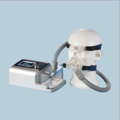
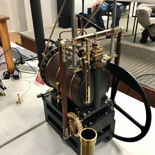
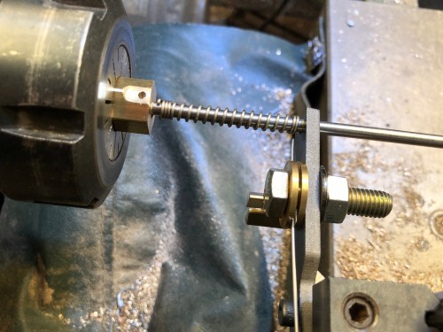
The CPAP machine and nose mask.   The tubing is much longer than shown.  The perspex tank contains water to humidify the inspired air.
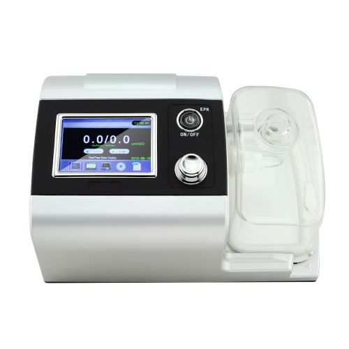
s-l1600.jpg

The CPAP machine


I could find no instructions, so I left the machine on the default settings.  Some weeks later I found an instruction booklet in a side pocket of the storage case, but it did not offer any information about settings.  I guess that normally there would be a doctor doing the settings, based on tests.   Fortunately I have a friend who is using a CPAP machine for sleep apnoea, and the default settings of my machine were very close to the ones which were prescribed for him, so I continued with the default settings.

First night.   I was warned by my friend that it takes about a month to become used to the CPAP, so I was not too perterbed by the mask and tubing waking me up every time I moved.  My wife had the best night’s sleep which she has had in years, because I did not snore AT ALL.  The machine makes a low whirring noise, which is barely noticeable.  Being forced to nose breath, because the positive pressure almost totally stops mouth inspiration, is a very odd sensation, but I was very aware that the 10cm of water pressure was profoundly affecting my breathing.  I was totally unable to deliberately snore while awake, and when asleep I was not snoring at all even when flat on my back.

First week.  I fiddled a bit with the pressures, but the default 10cm water pressure (0.14psi) seemed best.  I used the air humidifier.  The air is filtered.  Several times I woke and ripped the mask off, but after a month of use, that happens rarely.

First month.  I got the software working eventually, and I was delighted to see that I have had no snoring events or apnoea events at all.  My duration of sleep has gradually increased from an hour or two each night, to 5-6 hours per night.    My wife is absolutely rapt.   Her only complaint is that I sometimes remove the CPAP in the morning, then go back to sleep for another hour or two, during which time I revert to snoring.

I like to read in bed for an hour or more before I drop off to sleep.  I cannot wear my reading glasses with the CPAP in place.  So I read until I become sleepy, then pull on the mask and turn on the CPAP.  Usually I am asleep within minutes, which is a big improvement on pre-CPAP.

Either that, or I listen to podcasts with earplugs.  But the CPAP tubing and earplug cables do tend to get a bit tangled, so I usually read.  It helps to pin the CPAP tube to the pillow, with a lot of slack to allow for turning in bed.

So, after a month I have noticed that I never nap during the day, compared with most days pre-CPAP.  My tinnitus (ringing in the ears) is much less pronounced now.  I do not feel sleepy when driving.  I would like to say that my energy levels have improved, but that does not seem different.  I am hoping that my borderline high blood pressure will have settled, when next checked.

Overall, this has been a major improvement in my life. IFLT.  (technology, not Trump).


Steam Trains

Two of my grandchildren are identical twins.  Here is a recent photo of one of them.  Not much point showing a photo of the other one.  He is identical.

IMG_5259.JPG

Not sure which one this is.  They really are identical.  He is planning to join a circus.

Anyway, I had made a wooden train set for my other grandchildren, and my other daughter, the mother of the twins, suggested that the twins should have one also.   I decided to CNC most of the parts, and it was not much more time to make two compared to one, so here they are.

IMG_5467.JPG

The design, slightly modified,  is from a book by Jim Makowicki “Making Heirloom Toys”.  The trains are ready for painting by SWMBO.   She is planning to use wood dyes, and finishing with a clear laquer.

The materials are whatever I could find in my workshop, so there is an eclectic mixture of Australian hardwoods, plywood, and pine.   The panels were all CNC milled, and the chimneys and domes were CNC turned.

It has been a fun project.  I will post a photo when they are coloured.

Traction Engine Disappointment

I had inspected a 20 year old traction engine, 3″ scale so about 1.5m long, never been fired, just run on compressed air, and appeared to be in excellent condition.

The seller did not have a price, so after discussing with SWMBO who was surprisingly supportive of my passion, I rang the seller with an offer.  I did not really know what it was worth, but I made what I thought was a reasonable offer.

The seller immediately accepted the offer.

Had I offered too much?

Oh well.  I would press ahead.  I made an arrangement to pay and pick up the engine 4 days later.  I needed some time to get the cash and there was an unavoidable baby sitting day in between.

So 4 days later I hitched up the trailer and set off.  Just as I was driving out the gate, the phone rang once, then a message came through.

The seller had woken up with a bad feeling, and decided to not sell after all.  Asked for a return call.

I was feeling very disappointed and a bit cross, so I did not ring him, but acknowledged the call with a message.

Had I offered too little, and the seller had second thoughts?

Did he really intend to sell in the first place?

A susbsequent email from me has not been answered.

I did consider consulting a lawyer about breach of verbal contract, but there was nothing in writing.  So I am moving on.  Just pissed off.

Now I am looking for another traction engine, preferably requiring completion or repairs.

Heat in the workshop. Heaven!

Today I fired up the pipe heater which I have welded up over the past few days.

Fantastic!!

I was so keen to get warm on this 10 degree celcius day, that I deferred water proofing the flue.

And of course it rained!

heater fire 2.JPG

I forgot to bring some newspaper or kindling, so I used a propane torch to get the wood burning.

Within 5 minutes the temperature of the burner was over 200c, and in an hour it was 350 degrees celcius/ 660 fahrenheit.  Heaven.

heater finished.JPG

The shape of the furnace accepts wood up to 1400mm long.   The handle at the bottom is the ash tray.  The hefty looking handle above is for the furnace door.   The bit of RHS on the floor is so I can open the door when it is hot.

spacer for 2 layer flue.JPG

This is the external sheath of the flue.  The strip of corrugated iron is to separate the hot internal flue from the cooler external layer.

And then it rained!   And I had not installed the waterproofing fitting to the roof.   So water poured down onto the heater, and filled my workshop with steam.!!

Error
This video doesn’t exist

Despite today being only 10 deg celcius, I happily machined away until 6pm.  2 hours later than I usually stop due to the cold.

Then I had to go home to cook dinner.   SWMBO was getting hungry.

Another Diversion from The Triple

My model engineering club (GSMEE) has an annual competition build.  This year it is a small horizontal reversing steam engine.

IMG_5210.JPG

So I have taken another break from the triple to build the HME.  I have redrawn the plans to make my model 40% bigger, and also to accept metric fasteners.

IMG_5197.JPG

The HME blanks for the base, the cylinder block, the flywheel pillar and the flywheel.  The only stainless steel I had in my junkbox, er storage facility, had a  big hole in the middle, so I filled that with brass.

All was going well, and I spent almost a day making the piston head guide. Then finished off by making the guide rod and block.   I decided to take another thou off the guide block, and set the lathe going.

And heard an ominous bang.

IMG_5209

I had forgotten to remove the piston head guide from the from the piston before I restarted the lathe.  Destruction.  The lump at the bottom is another piece of brass, ready to be turned into another head guide.  I had run out of suitably sized brass, so I silver soldered a length of rod to some square section.  A day later and the new piston head guide is now made.  

At least I know from this (and other crashes), that the second part is always made much faster than the first.

And on a different subject, I recently bought on Fleabay a self centering 4 jaw chuck.

IMG_5201.JPG

It does not replace the independent jaw 4 jaw chuck for accurate work, but will be useful for turning small square stock.  Also, I plan to make a backing plate for it to fit into the tailstock, so it will hold taps.

Making Hubcaps

IMG_5140

I made 5 of these

Hubcap blank.JPG

The 50mm diameter aluminium blank had a 12mm bolt inserted into a blind threaded hole.  The bolt was held in the lathe chuck.

The 2 short videos which follow show 1. the final rough cut 2. the finish cut.

The shape was drawn as a DXF file using CAD, the G code was generated using Ezilathe, and the lathe was controlled with Mach3.


Error
This video doesn’t exist


Error
This video doesn’t exist

Total CNC turning time was 16 minutes per hubcap, plus cutting the groove for the O-ring, then a quick polish with a cleaning pad.

Chariot Racing

Another little job for my CNC lathe.

A fellow club member asked me to turn some hub caps for his car restoration.  And the shape was a bit unusual.

This is the first effort at complying with his request.

IMG_5140.JPG

It is aluminium, and will be held in position with an O-ring in the groove.

If I had put a knife edge on it he could have justified new car number plates…..

BEN-HUR

Metalworking for a cabinet maker

Our model engineering club has been locked out of our club rooms because MOULD has been detected in the building.   Apparently a lengthy process to reduce the mould to acceptable levels.  (note to self…. make sure that the inspectors never set foot in our house).

So our meetings have been held in various locations, including a sports centre and a basketball building.   I feel quite virtuous when I enter these buildings, but for some reason I do not feel any fitter when I exit.

A recent day meeting was held at my farm workshop.  Not my farm anymore, just the buildings.

walls-of-constantinople

Not that one….   the other one.

And one of our more senior members requested a display of CNC machining, from design to product.

So, I drew up a finial which was required to complete a bookcase which I had built 30 years ago.  Then imported the DXF drawing file into “Ezilathe”.

Ezilathe on screen.JPG

Showing Stuart Tankard, the author of Ezilathe, scrutinizing my drawing ….  and offering excellent suggestions for improvement using Ezilathe.

Then used Ezilathe to generate the G codes…..

Then to the CNC lathe…..

turning the finial.JPG

CNC turning the finial in 51mm brass rod.  1600rpm, 100mm/min.  Controlled by Mach 3 Turn.  I removed the tailstock shortly after this photo was taken, to permit completion of the ball.

GSMEE CNC close.JPG

Some GSMEE members watching the CNC turning.  I spent 3 days clearing up the workshop so the 16 members could fit in.   Amazing how much space was revealed in the workshop.   This is the Taiwanese lathe which I converted to CNC.  See old posts for details of the conversion.

I watched anxiously as the part was gradually revealed.  Admittedly, I had had a test run in wood to check the parameters, but this was the first run in metal.

finial in hand.JPG

The finial.  The bar stock was parted later.

finial on bookcase

Bookcase finally finished, after 30 years.

If you are interested in CNC lathe work, you should take a look at “Ezilathe”.  It is superb.

If you are on Facebook, (of course you are if you are reading this), you might like to take a look at the GSMEE Facebook site.


Swap Meet Bargains

Yesterday I travelled to Ballarat, (Victoria, Australia) to a swap meet which was held on 22 acres at the airfield.

Most of the stuff in the thousands of sites, was junk from shed and farm cleanouts.  However, despite rapidly walking up and down the rows, I did not quite cover all of the sites.  My Apple watch indicated that I had walked 18km (11.2 miles) and much of that was carrying a backpack full of bought items, so it was no wonder that my ankles were aching at the end of it.

I was really only interested in the few sites which had tools from factory closures.  But my eye was drawn to the very old Caterpillar crawler tractor, a 2 tonner, not too derelict except for a broken exhaust manifold and some rusted growsers.  $AUD9500, so I kept on walking.   Lots of elderly, old and antique cars, motor bikes, and vehicular bits and pieces.

The following photos show most of the stuff which I bought, and some prices (except for the ones which SWMBO must never discover).

ballarat-swap-meet-2

A Japanese woodworker’s chisel.  9 mm wide.  Razer sharp, oak handle.  I buy one of these at each Ballarat swap meet from the same seller, a lovely Japanese woodworker who lives and works in Victoria.  These chisels are a pleasure to use.  $AUD25

Ballarat Swap Meet - 4.jpg

This was a bargain.  A set of good quality English BA open ender spanners, probably unused, for $AUD8

ballarat-swap-meet-3

I dont know what this is called, but it has an INT40 taper, and bolts to the workbench or mill for inserting and removing cutters from the toolholholder, and avoiding the cutter dropping down and being damaged.  Is it a tool setter?  Anyway, $AUD40

Ballarat Swap Meet - 5.jpg

Used but sharp, quality brands.  Carbide ball nose end mill, countersink bit, T slot cutter, and 1/4″ BSP spiral tap. $AUD30

ballarat-swap-meet-6

A new, interesting woodworking cutter, carbide, with left and right hand spirals to avoid surface furring.  $AUD10

Ballarat Swap Meet - 7.jpg

3 Mitutoyo telescoping gauges.  $AUD10

I mulled over a Mitutoyo 1000mm vernier caliper in perfect condition for $AUD300, but decided that it was a wanted rather than needed item, and walked on.

ballarat-swap-meet-12

A box of 12 brand new quality Wiltshire triangular files. $AUD12

ballarat-swap-meet-13

2 very nice Moore and Wright thread gauges, which have BA and Acme threads as well as metric and Imperial angles.  $AUD6

Ballarat Swap Meet - 14.jpg

A box of metric counterbores.  Not cheap, but good price considering the German quality, and condition.  $AUD55

Ballarat Swap Meet - 15.jpg

Small die holder, Sidchrome 10mm spanner, tiny Dowidatadjuster and new box of inserts.  All useful.  About $AUD45

ballarat-swap-meet-11

Chesterman vernier height gauge.  Unusual triangular column. Beautiful condition, complete range of accessories, in a lined box.  Metric and Imperial.  Price not to be dislosed to SWMBO.

ballarat-swap-meet-1

These are brass wick type oilers which I will give to the local Vintage Machinery Society.  No markings.

ballarat-swap-meet-8

My brother was a navigator in the Australian Air Force many years ago, before the age of satellite navigation.  He would sight the stars using a sextant something like this to calculate the plane’s position, while standing in a glass dome in the roof of the aircraft.  (I think that I got that description approximately correct).   He once told me that he would like to have a sextant again, so when I spotted this at the swap meet, and the price was OK, I decided to get it for him.  Maybe it will make up for all of those forgotten birthdays.  So little brother, leave some room in your suitcase when you next visit.  I will leave the clean up and renovation to you.

ballarat-swap-meet-9

Elliott Bros London.

ballarat-swap-meet-10

It looks fairly complete and intact.  Of course I have no idea how it works.

Turkish Bombard – the barrel mouth

IMG_4572.JPG

Except for a name plate I have finshed the bombard.  The floral design at 12, 4 and 8 is not as clear as I wished, and the Arabic script at 2, 6 and 10 is even worse.  But it is cut in wood, and it is a first effort at such work, and it is not easily seen in a model only 106mm 4.2″ diameter, so I am reasonably satisfied.

Also, this was always a prototype, in wood, and I have not totally dismissed the idea of making it in cast iron or brass.  In metal I am sure that the detail work would be a lot finer.

Turkish Bombard. The Barrel Script

Well, I bought a pair of NSK bearings for the Z axis of my CNC mill, and removed the old ones and inserted the new ones.  Cost $AUD 200.  Plus 2 or 3 half  days of  dirty heavy work.    And the problem persisted!!@!@

OK.  Time to get an expert opinion.  Here comes the cavalry.  Thank goodness for my expert friend Stuart T.

Very puzzling.  Even for Stuart.  There was some unwanted movement in the Z axis (about 2mm), despite being apparently properly installed.  Not a problem with the ballscrew or ballnut.  Even Stuart was puzzled.

“have you got any left over bits and pieces?  Is it all installed the way it was before?”

To cut the story short, we installed a thicker washer below the locknuts, and it seemed the problem was fixed.  Or was it?

Today I did another test run of the bombard mouth Arabic script.  Worked fine.  OK.  Time to finish the bombard.

IMG_4559.JPG

Here is the finished result, ready for painting.  I have used a 20 degree engraving carbide bit with a 0.2mm flat end.  There is some loss of fine detail but it is I think, adequate.  When it is painted, the filling putty above the pin screws (the white circles) will be invisible.  The engraving took a total of about 60 minutes, at 500mm/minute, 15,000 rpm.

IMG_4554.JPG

The setup.   A large angle plate clamped to the table.  The work clamped to the angle plate.

The translation of the Arabic script is “Help O God the Sultan Mehmet Khan son of Murad. The work of Munir Ali in the month of Rejeb. In the year 868.”

Turkish Bombard. The Arabic Script.

A little unfinished business on my model bombard is the Arabic script and floral decoration around the barrel mouth.

bombard-mouth

XIX.164 / 19-00164 Detail of muzzle of a great bronze gun. Turkish, dated 1464 Royal Armouries Museum, Leeds LS10 1LT Transparency tr-1185 Imacon Flextight Precision II

This is what I have managed so far….

IMG_4529.JPG

It is a practice run in scrap wood.

Some of the detail has disappeared because I used a milling cutter with an end width of 0.5mm.  Next time I will add another step using a cutter with a sharp point, and a lot more of the fine detail will appear.

That pattern took a total of 80 minutes to CNC mill, with the feed rate set at 500 mm/min.

Unfortunately my CNC mill developed a problem with the Z axis, probably due to a worn out end bearing.  I am hoping that it is not the ball screw nut.  Now in the process of removing the bearing. A heavy, awkward, dirty job.

When the mill is working again I will mill the actual bombard model and post some pics.

Computer graphics is not my strong point.  To get the CNC mill to cut that pattern I did the following..

IMG_4531.JPG

  1. Enlarged the photo, outlined the tracery and the script, then traced the outline onto tracing paper.  That 550 year old pattern is worn and hard to define in many places.  Quite a bit of guess work.  Lucky that almost no-one can read ancient Arabic script these days.
  2. Scanned the tracing and loaded the scan into Corel Draw
  3. Used Corel Draw to smooth the curves, and make 3 copies in an array of the floral design
  4. Converted the drawing to bitmap file (bmp)
  5. Used V Carve Pro to convert the bmp file to vectors
  6. Used V Carve Pro to generate the CNC G codes
  7. CNC milled the scrap wood at 16000rpm, using a 3.2mm carbide cutter

After the triple

I am back onto the triple expansion steam engine, after putting it aside for most of 2016.  I am guessing that it is about 75% completed.  I have been struggling with this project due to poor plans, no instructions and some lack of skill and knowledge.

When I was well into the project, a colleague pointed out that detailed instructions existed in some articles published in 1985 (Model Engineer, Bertinat).  I obtained the articles, and subsequent progress has been greatly assisted, but unfortunately some errors had already crept into my work, and these have not been easily or completely rectified.

So now I am back into it.  And I would hope to have it finished and working by the end of the year.  Watch for pictures when there is something to show.

I am already thinking about what will follow the triple.  Maybe a Harrison 1 clock? (of “Longitude” fame.)  Looking for some plans.

h1

Or maybe some more artillery?  How about a working  model  trebuchet?  Now that does have some appeal.  There are some plans on the Net, but they look over simplistic.  I am thinking of a more historically accurate model.  The following picture is from an old French encyclopaedia.  But I might have to abandon my preferred scale of 1:10 because the original was about 12 meters long.  But on the other hand……

trebuchet1.jpg


It does have some interesting features.  The ratcheted windlass, the travelling pulley, the trigger mechanism (“pulling the pin”), and the projectile release mechanism (trying to avoid the projectile going up vertically).


Model Ottoman Bombard – Painting

I would have preferred that the title of this blog was “Finishing the Ottoman Bombard”, but I am still waiting for the vectors of the barrel mouth decorations and Arabic (?) writing, and the touch hole.

But I have at least painted the bombard, and the pictures follow.  You will notice that I have not attempted to reproduce the bronze or copper colours of the orginal in Fort Nelson.  Partly because I doubted my ability to make painting such variegated patterns realistic, and partly because the cannon would not have looked like that in its heyday of 1464.  It would probably have been either black, like most SBML cannons (smooth bore muzzle loading), or possibly gaudy golds and reds and blues like other medieval items.  So I painted it black.  I like it.  If I get evidence that it should be more colourful I can change it later.

IMG_4429.JPG

First coat – Primer.  Hmmm… interesting colour.

IMG_4434.JPG

Next coat – matt black brushed on, to fill the hairline wood cracks.  Incidentally, the (dirty) parquetry floor is also made from the red gum house stumps from which the cannon is made.

IMG_4447.JPG

final two coats –  matt black, from a spray can. 

IMG_4458.JPG

So there it is, finished except for the barrel mouth engraving, and the touch hole.  Now what to do with it…   SWMBO says it might be useful as an umbrella stand.

IMG_4460.JPG

The breech.  25mm diameter explosion chamber.  1:10 scale

IMG_4461.JPG

The barrel, 63mm bore.

IMG_4462.JPG

Assembled.  The model is 520mm long.

IMG_4464.JPG

It does need some decoration

turkish-bombard-plan

Ottoman Bombard Photo to Vector

Bombard mouth.jpg

This is the low res photo from Fort Nelson.  High res photo on its way.

In the meantime, I have contracted with a US firm to convert the picture to vectors.  More $US.  ($US50 to be exact).

I am not sure that this is going to work.  But I will report to you.

I do wonder what that the Arabic/Turkish writing means.  Does anyone know?  I am pretty sure  that it is not complimentary to Christians/Westerners/Non Muslims.  Maybe it is just an instruction not to look before the touch hole is touched.  Or “do not stand here”.

PS.  Note added 17 Oct 2016.    The translation is   “Help O God the Sultan Mehmet Khan son of Murad.  The work of Munir Ali in the month of Rejeb.  In the year 868.”

868 = 1464 ce.


TURKISH BOMBARD- HELP!

Does anyone have a decent photograph of the writing on the muzzle?

I have repeatedly hunted through every picture which I can find on the net, but they are either taken at an angle, or too poor quality to be useable.

Does anyone have a photograph which I could beg buy or borrow?

I also need a photo of the touch hole.

I have contacted the Fort Nelson Armoury Museum, but not too surprisingly there was no response.

Is there someone in the Portsmouth UK area who could pop in and take some pics for me?

POSTSCRIPT:  October 5.   I have had 2 excellent and positive responses to my appeal.

First, reader Richard sent me a connection to a Turkish Dr/Professor, who has made a 1:25 model of the bombard using 3D printing.  (at least that is how I think he has done it.  My Turkish is non existent).  I am following this lead.

Secondly I have had a response from Fort Nelson Armoury, with a good photo of the barrel mouth, and a high res photo on the way, after payment of a significant, but not unreasonable fee.  Isn’t the Internet wonderful!!


TURKISH BOMBARD – the real thing

I have found this video to be particularly useful in my modelling of the Ottoman bombard. The subject of this video is the gun that the Turkish sultan gifted to Queen Victoria when the Brits and the Turks were allies.  It might be one of the guns which fired on the British fleet in 1807, when it (the gun) was 343 years old!

Notice the colour.  It is aged bronze.  I am thinking about how to reproduce that colour on my model.


Length of the assembled gun 5.2m (17′)

Bore 635mm

Breech weight 8942kg

Barrel weight 8128kg

Average weight of shot 307kg

the model is at a scale of 1:10.  photos soon.  being painted.


Modelling A Turkish Bombard- The Pins

b281d1ba4455df20d7b832411bb00443

There are 16 pins at each end of each section of the cannon.

These were certainly used as leverage points, for very strong men with large levers to rotate the 8-9  tonne segments against each other to engage and tighten the screw.

I cannot see how the pins would have been cast with the breech and barrel.  For my model I decided to make separate pins and fit them into the gap between the big rings, then insert a grub screw through both rings and the pin.  The holes are then filled.

I wonder if a similar method was used in 1464.  I would love to have a close look at the original cannon to figure this out.  From the photographs, I can see no evidence of later insertion of pins, but neither can I see how it would have been done any other way.

IMG_4373.JPG

Drilling the holes for the grub screws

IMG_4395.JPG

In order to continue with red gum, I made my own pins.  This is the setup.  The blank is held approximately centre in a 4 jaw….

IMG_4396.JPG

…and the pins are turned, centre drilled, drilled, cut to length,  and tapped M4.  64 altogether.

IMG_4421.JPG

The M4 x 25mm grubscrew is screwed into the pin.  The wood join is super glued.  Also, I am attempting to patch the worst of the thread tearouts.

IMG_4423.JPG

Using a battery screwdriver to insert the grub screws.  The pins protrude above the ring surface for a reason..


IMG_4424.JPG

Sanding the pins flush with the rings.  Check the photo of the original 1464 model.  There is also some wood filler in other splits.  Not surprising after holding up a house for 70 years.

The holes are now filled with wood filler, and will be sanded flush.  They should be invisible after painting.

Next the painting, the stands, and some cannon balls.  How to reproduce that aged copper colour…


Modelling a Turkish Bombard -4 Decoration

The decoration around the barrel is formed by a repeating pattern, which when milled, very cleverly forms 2 identical patterns.  One is excavated and one is the original barrel surface.  You will see what I mean if you look at the pictures in the earlier blog, and the video below.

It took me an evening of experimenting on the computer to work out the system and draw it.

bombard-pattern3

Then I measured the diameters of the 2 gun components, calculated the circumference, (OK it is not rocket science.   3.142 times diameter), then working out the number of identical shapes which would fit around the 2 different diameters, at the same size and spacing.   Amazingly, it took 18 shapes to fit almost exactly around the barrel, and 16 of identical size almost exactly around the breech.  the angular spacing was 20 degrees and 22.5 degrees.

Then the shape was imported into V-Carve Pro, and G codes were generated.

My CNC mill does not have a 4th axis, so I used a dividing head to move the workpiece at the precise angles.  See the setup in the video.  That meant that the pattern was engraved into 16 and 18 flat surfaces, rather than a continuous cylinder as on the original.

It worked very well.  There were minor compromises due to the shapes being milled with a fine end mill but when you look at the pics I hope that you will agree that it is effective.

I calculated that the milling had to be at a maximum depth of 2mm in order to cope with the curvature, but if I do it again,  I would reduce the depth by 25%.

The first part of the video is a shot of CNC drilling.  Then the CNC routing of the repeating patterns.  Each angular setting of the pattern took 4 minutes to complete.  136 minutes altogether.  In reality, it took a whole day, most of which was spent doing the setups.


Bombard Model-3 turning the barrel

Another session or two, and this project is complete.

Now how do I make a cannon ball 62-63 mm diameter?  In wood will be ok?  Does not have to be granite.  I could make a mould and cast it in aluminium or lead, but stone would be authentic…..   thinking.

ps.  Re cannon balls.  I will cast them, in cement!   Now, how to make a mould.

Bombard Model -2. Big Thread

The breech and the barrel are joined with a very large thread.  On my 1:10 scale model it is 60mm diameter, and has a pitch of 6 mm.  These dimensions are measured off Internet photos of the original bombard, so they might not be faithfully accurate to the original bombard.  If anyone has accurate plans of the bombard I would be very interested to hear from them.

I experimented with various spindle speeds, feed rates, depth of cut, and finally decided that red gum wood is not the ideal material to be cutting a thread with sharp points.  However, at 200rpm, and taking 50 cuts to reach the full depth, and using a very sharp tool, the end result was OK.  I will fill the tearouts.

In order to make a functional join in the wooden cannon, I truncated the apex of the thread.  In the gunmetal version I will attempt a more faithful to the original, sharp look.

For some reason, the wood held together better during the internal thread cutting than the external.


The male thread was cut on my newly CNC converted lathe,  between centres, but the fixed steady on that lathe was just too small to hold the barrel, so the internal thread was cut on my bigger Chinese lathe.

Next I will bore the barrel to 63mm, then turn the exterior of the barrel.


Turkish Bombard 1:10 scale

Just for fun I will use my newly converted CNC lathe to make a 1:10 bombard.  The original was cast in 1464 and was thought to be a close copy of the bombards which Mehmet 2 (“the conqueror”) used to breach the walls of Constantinople in 1453.  There are several of these bombards still in existence, including one in UK, which was given to Queen Victoria by the then Turkish Sultan.

These bombards were last used, against the British, in 1807, when a British warship was holed with substantial loss of life.  Pretty amazing for a 340 year old weapon.

images

5.2 meters long, 1.060 meter diameter. 16.8 tonnes.

b281d1ba4455df20d7b832411bb00443

The large thread connected the halves.  Easier transportation, and casting.


images

Is this Turkish or Arabic?

images

Granite balls are 630mm diameter.


tembokkotakonstantinopel

A reconstruction of the walls of Constantinople, with moat.  Almost 1000 years old in 1453  

walls-of-constantinople

And as they are today.  Massive.  High.

29962555-Huge-siege-the-final-assault-and-fall-of-Constantinople.jpg

Huge siege cannon used in the final assault and fall of Constantinople in 1453. Diorama in Askeri Museum, Istanbul, Turkey.  The bombards were probably dug in, to manage the massive recoil, and concentrate the aim at a particular wall section.  There is a wooden structure built around the cannon in the background of this modern picture.  As far as I know there are no surviving  wooden structures like this.  Nor have I come across any old pictures, but if anyone knows of any I would be very interested.  The bombards took about 3 hours to cool, cleanout and reload.  

p1090990.jpg

My model will be about 520mm long.  I would like to make it from bronze, or gunmetal as in the original.  Any mistakes will be costly.

So I have decided to make a prototype in wood.  That will test my drawing, the machining procedure, and the final appearance.  Not to mention how the CNC lathe will handle the task.

I will use a very dense, tight grained Australian hardwood (red gum).  The wood was salvaged when my house stumps were replaced with concrete.  Some was used to make parquetry, and the rest was put aside for possible future use.  Such as this.

IMG_4313.JPG

About to cut off the below ground section of a 70 year old house stump.

IMG_4320.JPG

A 5hp metal lathe with a tungsten bit chomps through the hard dry wood.

IMG_4322.JPG

I turned 6 lengths before I found 2 that were satisfactory.  The rest had sap holes or splits.

I have used Ezilathe to generate the G codes.

to be continued….


A Matter of Scale

Before I get onto a brief reflection about scale, the photo below shows 2 cannon barrels.

The big one was what impelled me to converting a manual lathe into a CNC lathe.  That time consuming, costly, and ultimately very satisfying project, started because the CNC lathe which I used to turn the big barrel could only handle the job by doing it in two stages…. doing the breech first then the muzzle.  That was due to the big barrel being too long for the lathe, at 300mm (12″).

The small barrel was a test for the CNC converted lathe just finished, being the first complicated shape which I have made.   To save on material, I made it at exactly half the scale of the big one, ie 150mm long (6″).

IMG_4291.JPG

Comparing the two barrels reminded me, that if an object is twice as big as another, in all 3 dimensions (height, width, depth), it is 8 times as heavy.   And any projectile, and weight of black powder, would also be 8 times the weight.  But the wall thickness of the explosion chamber is only TWICE as thick.

My point is, that if scale is maintained, the smaller the cannon, steam engine, boiler, whatever…..  the less likely it is to explode.

Not that these cannons will ever be fired.  Just hypothetically.

Steam Engine Oilers

Knowing that I have an interest in CNC machining, Tom, from the Vintage Machinery Club in Geelong asked me to make a pair of oilers for a very old Wedlake and Dendy steam engine.  The engine is a large (to me anyway) stationary engine, which is run on steam several times each year.  The oilers for the cross slides were missing.

We searched the Internet for pictures of W&D steam engines, but could find no pictures or diagrams of the oilers.  So Tom sketched a design, and I drew a CAD diagram.  The dimensions were finally determined by the materials which I had available…  some 1.5″ brass rod and some 1.5″ copper tube.

This is the almost finished product.

IMG_4250.JPG

Just needs 1/4″ BSPT fittings and and oil wick tube so they can be fitted to the engine.

IMG_4222.JPG

The copper tube silver soldered to the brass cylinders (top), the brass blanks for the lids (bottom) and the mandrel to hold the assembly (bottom centre) during CNC turning and drilling.

IMG_4246.JPG

The mandrel to hold the body (left) and the mandrel for the lid (right).  The cap screw head and hole in the mandrel have a 2 degree taper.  The slits were cut with a 1mm thick friction blade.

IMG_4243.JPG

Rough turning the base.

IMG_4231.JPG

Turning the lid.  The mandrel is held in an ER32 collet chuck

IMG_4245.JPG

Engraving the lid.  Using a mister for cooling and lubrication.  16000rpm, 200mm/min, 90 degree TC engraving cutter.

IMG_4251.JPG

The oilers work by wicking the oil from the reservoir into a tube which drains through the base onto the engine slide.  When the wick tubes are fitted the oilers can be fitted to the engine.

IMG_3196.JPG

The 1865 Wedlake and Dendy

IMG_3195.JPG

1865

My lathe is a Boxford TCL125, using Mach3.  The G code is generated using Ezilathe.

Below is a link to an oil cup from “USS Monitor”, of American civil war fame.   One of the first ironclads, powered only by steam.

http://www.marinersmuseum.org/blog/2010/04/one-oil-cup-down/

(ps. The  lathe which I was converting to CNC was the subject of previous posts and is now working, but needs some guards fitted and a bit of fine tuning.)

MORE ANCIENT GREEK TECHNOLOGY, THE ANTIKYTHERA MECHANISM

This mechanism was discovered in 1901, in a Roman era shipwreck, off the Greek island of Antikythera, which is a bit north of Crete.

It has been dated to between 100BCE and 205BCE, with the older date considered the best estimate.  ie, about 2200 years old.  Experts believe that its makers were Greek.

It is currently housed in the Greek National Archeological Museum in Athens.

IMG_4180.JPG

Not much at first glance, but when it was examined with modern scanning and X ray techniques…

Look it up on Wikipedia..

https://en.wikipedia.org/wiki/Antikythera_mechanism

According to the Wikipedia entry the gear teeth are too irregular to have been machine cut,

but watch the computer reconstruction.   Could you make this machine without a lathe and gear cutters?

How much more technology did the ancients have that has not survived the ravages of time?   A lathe for example.

ANCIENT GREEK MACHINING

I recently had a light globe switched on in my brain.

I was holidaying in Athens (the one in Greece), and was gobsmacked by the huge, fabulous collection of statues, mosaics, ceramics, gold jewellery and masks, bronze and iron weapons in the National Archeological Museum.   I took many photos, and might post some in later blogs.

Three items sent shivers down my spine.

  1. The gold death mask of Agamemnon (probably not Agamemnon’s but that is another story).
  2. The Antikythera machine.   More about that in a future post.
  3. A gynaecological speculum.

There was a display with many surgical instruments.  These have been found at various archeological digs in Greece, and while not precisely dated (at least not labelled) they are mostly from 500-200 BCE.

My eye was immediately drawn to an instrument which looked very familiar.  I was a gynaecologist in my previous life, and this could have come from my instruments. (except that the dark bronze surface might not have been acceptable to patients).

DSC_0570.JPG

Not a great photo, through a glass cover, and ISO cranked up to several thousand.

The instrument is labelled a vaginal dilator, but I am quite certain that it is a vaginal speculum.  A speculum is used to inspect the vaginal walls and uterine cervix.  (That might be too much information my metal working/ engine making/ machinery minded readers.  If so, too bad.)

It is said to be made of bronze.  The Ancient Greeks were highly skilled at metal casting, as evidenced by the many complex and beautiful bronze statues and weapons and implements on display.

It interested me for several reasons.  Bear in mind that not many archeology museum visitors are gynaecologists who know about making threads in metal.

It looks quite functional, and if cleaned up, given a shiny surface and sterilized it could be used today.

The threaded section is very regular and smooth.  I would loved to have taken some measurements of the thread with a micrometer, but had to be content with a prolonged inspection through the glass case.  The thread appears to me to be so regular, that it could not have been hand filed.  It must have been machine made.  I have seen hand made threads on medieval machines, and they are crude compared with this one.

Either this is not an ancient Greek instrument but a more modern instrument accidentally included in the display (pretty unlikely, considering the professionalism of the people involved).  (ps.  If you Google Pompeii speculum, you will see that similar instruments have been unearthed at Pompeii…  buried since 79ce.)

Or…..  the ancient Greeks had screw cutting lathes.

Ridiculous you say?

Wait until my next post about the Antikythera machine.  If if you just cannot wait, look it up.   It is mind blowing.


Workshop Tidy

I sometimes feel a bit ashamed when I have visitors at my workshop.

The reason is that when I am in the middle of a project, I really concentrate my energy on the decisions, the machining, working out how to fix the mistakes…

…. and tidying up as I go, is near the end of the list of must do’s.

Consequently, tools tend to be put aside at the spot where I have been using them.  And off cuts of steel or brass or wood or whatever, lay where they fall.

And as mentioned in a previous post, I have a policy of leaving swarf on the floor, to discourage wildlife from slithering into my workspace.  (see the old post about the tiger snake between the lathe and the milling machine).   And if you are not Australian, look up tiger snakes.   They are just about the most dangerous reptile on the planet.

So my workshop is not the tidy, organised sort of workspace which you might expect from a retired gynaecological surgeon.

But occasionally, the mess becomes so extreme, that I cannot find tools, I trip over stuff on the floor, everything is really dirty, and it is dangerous and embarrassing when visitors call in.  And some of those visitors have workshops where you could eat off the floor.

So yesterday I spent a whole day tidying, sorting, putting away tools, throwing out rubbish, and sweeping the floors.

What about the tiger snakes I sense you asking.

Well, here in the antipodes, we are in the depths of winter, and it is bloody cold.  And all sensible cold blooded reptiles are asleep in their homes. So for a few months it should be safe to sweep up the swarf.   Here’s hoping anyway.

Ball Screws -2

This is a brief post to give a 10/10 rating to an Ebay seller with whom I have had dealings recently.

I have bought 2 ball screws and ball screw covers and ball screw bearings in 3 separate transactions from a supplier in South Korea.

Postage was included in the “buy it now” price.  In one case I offered a lower price, which was accepted within minutes.

After paying by Paypal, I received confirmation within an hour in each case, that the item had been shipped (actually air freight by Fed Ex).

In each case the items were delivered to my door in Australia within 3 days!  (it takes 5 days to get a parcel posted from Melbourne to Geelong, a distance of 65km).

And in each parcel there was a very nicely handwritten card thanking me for the purchase, and promising support if there were any issues with the items.

One ball screw was brand new, repackaged as advertised.  The other was used, salvaged from used machinery, but in “as new” condition.   Both were C5 grade, which is normally stratospherically expensive and has to be specially ordered.  They were priced only slightly higher than new rolled (lower grade) ball screws.

They were very carefully packaged in heavy duty cardboard rolls with metal ends, and multiple layers of heavy plastic and foam sheeting.

I made a later purchase which involved the seller removing a part from a machine.  He added it to a parcel which I had also ordered and wrote that I could pay later for the part if I was satisfied with it.  The price for the part (a THK bearing) was $UAUD32.  The same part new here would cost $AUD400.

In every case, communications have been  answered within a few hours, polite, personalised and in excellent English.

My only complaint, and it probably relates to the shipping arrangements, is that there appears to be a size restriction on shipping to Australia, of about 1200mm.  (p.s.  apparently the “do not ship to Australia” are old adverts, and there are no restrictions now.  A message to dy-global is all that is required to get any item shipped).

I hope to deal again with this company.  The name is dy-global.  To find them you need to search Ebay USA, or use the international settings on Ebay Australia.

THROAT CUTTER WALL SMASHER

Some pics which we snapped a few years ago of a large bombard, sitting outside the wall of the “Throatcutter” castle (RumeliHisari), a few miles from Istanbul-Constantinople, overlooking the Bosphorus.  This castle was built by the Turks in order to control the Bosphorus waterway, just before they besieged Constantinople in 1453.

The cannon was clearly placed in this current position just for display.

Could this have been the one which breached the Theodosian walls in 1453?  It seems to be an  appropriate size and style.


large cannon2.jpg

That’s a younger me.  No name plate  about the cannon.


large cannon bore.jpg

The bore is about 600mm.  The narrow part near the breach is the powder explosion chamber, with an enormously thick wall.  The original cannon was recorded as requiring 60 oxen and 400 men to drag it from its casting place.  And a gun crew of 200 men.  Cast in one piece.  (later note:  not sure about cast in one piece.  I will be in Istanbul soon.  I will try to determine construction.)

This could well be the original Orban cannon.

Updated Notes :

The Orban cannon was recorded 8.2 metres (27 feet) long, so the one in the photos cannot be it, unless the recorded figures are exaggerated.  Orban did cast additional smaller cannons for Mehmet 2 for the seige.

The biggest Orban cannon at the seige was named “Basilica”.  It fired  stone balls weighing 272kg (600lbs) over 1.6km (1 mile).   Reload took 3 hours.  The stone balls were in short supply.  Not surprising, considering the labour which must have been involved in making them.

Orban is thought to have been Hungarian or possibly German.


COMPRESSED AIR ON THE CNC MILL

Compressed air is very, very useful on the milling machine.  The tool changer uses air for fast tightening and release.  And I often use air to clear the field of swarf, and shavings (yes, I use my mill for wood  too).

Recently, at the suggestion of Stuart L  of stusshed.com fame, I installed 2 semipermanent nozzles on the mill, with adjustable direction and pressure adjustments.  It has been a quantum leap improvement.

carronade - 1.jpg

The pic shows the jets aimed during CNC end milling of wood.  The wood shavings are blown away which makes it easier to see how the milling is progressing; blows them away from me which is safer and cleaner; and stops the chips being machined into the work, which leads to a cleaner cut.  It also improves any video or photo of the progress.  It must also cool the cutter, although not as effectively as a liquid coolant.  I have not tried using the misting attachment, which would improve the cooling, but at the cost of dampening the area and the work.

I particularly like the improvement experienced when machining brass or steel.  The swarf is removed from the advancing cutter, preventing it being re-machined and squashed into the workpiece.  I am noticing better surface finishes.  I also adjust the air direction to keep the swarf away from me;  particularly valuable when brass needles otherwise would be flying at me.

When cutting pockets, the air keeps the pocket free of swarf, and when using tiny endmills at high speeds I am experiencing fewer tool breakages.

This gadget was inexpensive ($AUD12) from China.  It does not work the compressor too hard when the volume is turned back as far as possible, but still adequate.  Although there are 2 jets, I find that only one at a time is adequate.

Recommended.

As an afterthought.   I rarely use coolant on my lathes, but an air stream on the cutter and workpiece would probably have similar advantages to those listed above.  I particularly wonder if it would assist during deep parting…   always a tense procedure.  I suspect that the cutter becomes hotter and expands more than the workpiece parting slot if there is no coolant.  I will mention the result of air cooling and chip clearing on the lathe in a later blog.

Lathe Conversion to CNC -2 and Wall Smashers

After removing most of the lathe gear which will not be required after the CNC conversion, the lathe is looking a bit naked.

The carriage apron, the lead screw, the back gears, the drive rod and control rods have all been removed.  Also the cross slide screw and handle.  The cross slide itself is temporarily removed, but available for measuring for fitting a ball screw.

I have now made accurate measurements and drawings of the lathe bed and carriage, in order to choose ball screws and nuts for the lead screw and cross slide.

The lead ball screw is easy.  There is plenty of room and machined surfaces for attachment.  I see no particular problems there.  Just time, careful machining and expense.  Chinese or Euro-American?  As usual, there is a big price difference and maybe not such a big quality difference as previously.   Looking at 25 or 32mm diameter, with 550-600mm of thread.

The cross slide ball screw is another matter.  The current cross slide square thread screw is 14mm diameter, and I would like to use a ball screw about the same size.  The problem is that a ball screw nut is considerably bulkier than the existing square thread nut, so some machining of the cross slide will be required to make space.  The cross slide dimensions are already fairly tight, to maximise the swing over the carriage.  I do not want to weaken the cross slide too much.  So it is all a bit tricky.  Time to consider options. And to get another opinion.

No lathe pics, so here are some of Turkish wall smashers.


Turkish cannon

This one was given to Queen Victoria by the Turkish sultan.  It was made about a decade after the fall of Constantinople.  It was cast in 2 halves.  There is a giant thread connecting the halves.  I imagine that the strange square holes are to allow levers to be inserted for the screwing by many strong men.  No double entendre  intended.


Turkish wall smasher


Turkish cannon and ball

This one could have been used to make the breach in the wall at the fall of Constantinople 1453.  That stone ball is 600mm diameter.  With no trunnions or other supporting mechanism the barrel was probably dug into the ground for support.  That would allow repeated shots at exactly the same point in the walls.  8-11 shots per day.  It was made for the invading Turks by Orban, a christian who had previously offered his services to the defending Byzantines.  The Byzantines whose empire by this time had been reduced to a tiny fraction plus the city itself, could not afford his services.  The rest is history.


CARRONADE VS LONG GUN


carronade - 1.jpg

Models 24lb long gun and 32 lb carronade.  1:10 scale.

In a shoot out, which would win?

Doubtless, at this range, there would be no winner.

But there were quite a few battles between ships equipped with these weapons in the Napoleonic wars, the first American civil war (the War of Independence), the 1812 war between Great Britain and the US, and many others.

The long gun, manned by 9-11 highly trained gun crew, fired a ball of 24lbs weight, up to 2000 yards, with some accuracy.  The largest long guns mounted on the biggest battleships (like “Victory”) fired  balls up to 42 lbs.

The carronade was operated by 4-6 men, and fired a ball in this case of 32 lbs, at three times the rate of a long gun, but with dismal accuracy beyond 500 yards.  They were much less expensive to buy and operate, and very popular with the bean counters.  Carronades fired balls up to 68 lbs.

Since most sea battles were fought at ranges much less than 500 yards, carronades were credited with many spectacular victories.  The British were so impressed that they installed carronades in addition to the usual long gun armament, to increase the overall firepower of their ships, but later they replaced the long guns with carronades in some ships.

carronade - 2.jpg

In the war of 1812 between the Brits and the US, while the Brits were simultaneously engaged in a life and death struggle with the Napoleon, they were often beaten by the newer and more powerful frigates of the small US navy.  One factor cited is that the British ships had fewer and less powerful long guns, and partly because they had changed over to carronades.   The US ships remained out of effective range of the British carronades while causing huge damage with their long guns.


carronade - 4.jpg

Short squat and ugly vs long and elegant and expensive.  Note: no SWMBO comments.


The carronade was used by the British navy for only half a century, vs 3 centuries for long guns.

They were both replaced by guns which were rifled, fired explosive shells, and were breech loaded.

For a very detailed analysis of these weapons, including original results of British Admiralty trials and summaries of many sea battles, see Adrian Caruana’s book, “The History of English Sea Ordnance” Vol 2, 1997.  If you can locate a copy.  I found one at the State Library of Victoria.


POLISHING TINY BRASS PARTS

My model carronade has quite a few very small metal (mostly brass) components.  They are fiddly and a bit difficult to hold while finishing (filing and sanding and polishing).

So I bought a tumbler which is designed for polishing metal jewelry and gemstones, and gave it a go.


carronade - 15.jpg

Enter a caption

It cost just under $300, including a kilo of stainless steel bits, and some polishing compound.  It is designed to run for weeks at a time when polishing rocks, but I find that 30-90 minutes is enough for my brass parts.


carronade - 14.jpg

The drum will hold 4lbs of parts.  Shown here are the stainless steel polishing bits.  The drum revolves quite slowly, about 30rpm.  Water is added so that the drum is just under 1/2 full.


carronade - 13

The before


carronade - 16

after 30 minutes.  It could use another 30-60 minutes of tumbling.  Not all of these bits are for the carronade.


carronade - 1.jpg

This is the sight for the carronade.  Complex and tiny and has sharp edges.  Ideal for the tumbler.  The CNC program diagram on the screen.

I am still experimenting with the tumbler.  So far I have used only the stainless steel shapes to do the polishing.  I will try some abrasive compounds soon.  Garnet dust seems to be the commonest abrasive.


carronade - 1.jpg

More bits for the tumbler


carronade - 7.jpg

A preview.  Almost finished.


CANNON BALLS FLOAT IN THIS LIQUID

OK,  so I am not quite ready to post my pics of the scale model carronade, and the number of hits and likes on this site is plummeting, so I am re-posting someone else’s video to retain your interest.  This is interesting!


Mercury has a melting point of -38 celsius, and a boiling point of 356 celsius.  It is 13.6  times as dense as water.  It is the only metal which is liquid at room temperature.

Mercury is very poisonous.  However it is a component of dental amalgam, used in tooth fillings, but it is calculated that you would need 490 fillings to reach toxic levels.  I hope so.

MACRAME FOR MACHINISTS

This video proves that you cannot fold paper more than 7 times.

It also shows what happens if you try.

It also shows what machinists with too much time on their hands get up to.

Enjoy


So, where is the macrame?  I sense you are asking.   Maybe I meant to title this “Origami for machinists”.   But just in case you are disappointed about the absence of macrame, I add the following…

Picture of rather attractive woman in knotted string bikini would not paste….    sorry.


OLDEST STEAM ENGINE- Model

Hero of Alexandria, in Roman Egypt, described a steam engine 2000 years ago.  He is credited with inventing the first steam engine, although it is very likely that he was just describing something already in existence as previously described by another Roman, Vitellius, a hundred or so years earlier.

Today I saw a working example of a Hero type engine, and it was much more impressive than I expected.  One of our club members has built 2 Hero engines, and the following video  shows one of them working.

I think that I will have to make one to show the grandchildren.

Click on the arrow to see another grossly amateurish video.

Incidentally, Emperor Nero, who hated his mother, put her in a ship which, as planned, fell apart when afloat with mummy dearest on board.  Unfortunately for Nero she could swim.  What is really interesting is that the ship is described as having some sort of mechanical propulsion system.  Maybe steam??


Seismic Wave Generator

To continue the posts about making the seismic wave generator.  See the previous post about water jet cutting the steel plates.

From what I am told, the generator is positioned, pinned to the ground, and hit on the ends with a sledge hammer.    Instruments pick up and measure the seismic waves in order to analyse what is beneath.

Sound is not required.  In fact sound is annoying and a disadvantage.

The operator stands on the generator while swinging the hammer.

So here is the finished item, ready to be delivered.  It weighs 20kg.


Striker - 1.jpg

The seismic generator, ready to be delivered.  The brass plate is to remind the user to wear safety glasses, safety boots and ear protection.   The holes in the impact plates are to permit aluminium plates to be attached if the situation absolutely requires no sparks.


Striker - 3

There are 10 ground pins.  Each pin is slightly tapered to make removal from asphalt or clay easier.   The pins are machined from 16mm set screws.  I imagine that 6 or 8 pins will be adequate to hold the generator in most surfaces.   The pins are removed for transport of course.

It will be interesting to hear how it performs.


THE POWER OF WATER

In these clips, 10mm thick steel is cut with a water jet machine.

As a first timer it was amazing to see.

The water is pumped through a tungsten carbide jet, under enormous pressure.  The water carries garnet dust, which does the actual cutting.

The steel is 10mm thick, but this machine will cut through 200mm thick steel!  It will cut wood, carpet, granite, marble, any metal, in fact any material except diamond and some glass.

The cut is accurate to within 0.1mm.  The kerf is 1mm.  The angle of divergence away from the vertical is approx 1 degree.

Click the arrow below to watch the 8 minute video.


German Engineering

I am waiting for the water jet cutting so I can do the machining and welding on the seismic wave generator.

In the meantime, the washing machine at home had been sounding very noisy lately.  I say that with confidence, because my hearing is so poor I am told that I need hearing aids.  And the washing machine sounded like an overloaded cement mixer, even to me.

But despite the noise, the Miele front loading machine still worked fine.  But the noise when spin drying was painful.

Our Miele machines tend to be changed at 20+ year intervals, and this one was only 15 years old.

So I did the manly thing, and got SWMBO to point out which was the dryer and which was the washing machine, and I took the washing machine apart to diagnose the problem. My prediction was that the main bearings had disintegrated, because the inner drum seemed very loose.

I undid the cabinet torx screws, carefully disconnected wires after taking photographs to record positions, separated pipes and flanges.  And asked my neighbour to help me lift out the drum.  It took two of us because it is bloody heavy.

You might be wondering at this point how a retired gynaecologist knows about washing machine repairs.

Well, the truth is, that he doesn’t.

But the internet, and particularly YouTube has information about “How To Do Anything”.  Including repairing Miele washing machines.

So here we were.  I had found the source of the noise.

Miele - 1.jpg

This is the main shaft and aluminium casting which holds the washing machine drum.  It has broken into 4 pieces.

How, you might ask, as I did, did that washing machine work for several months with this?

I dont know.

Must be German engineering.


p.s.  I rather cheekily emailed Miele Australia to enquire about about spare parts.  Within 24 hours I had a polite reply that a replacement drum with attached casting and shaft was available, at a cost of $AUD750. (!!)

In the meantime, in fact before I had even started the teardown, SWMBO had gone out and bought a replacement washing machine.  She of little faith!

So the old machine sits there in bits.  I guess that it will go to the recycler.  But I am sort of hoping that a W828 Miele washing machine will turn up on Ebay, so I can use the parts to fix mine, just to see if I can put it all together again.


Shear Wave Seismic Source

You are probably wondering WTF this is about.

So was I, when I was asked to consider making one.

I gather that researchers and geologists use them to work out what is going on in a geological sense underneath our feet.

Seismic waves are generated from ground level, and instruments pick up frequency changes and time delays, providing information about what is happening below.

The seismic wave generator has the following requirements…

  1. it is anchored or spiked to the ground surface

2.  the spikes must be able to penetrate all types of ground surfaces, including asphalt, and be removable from the ground, and from the device.

3. it must be transportable by hand i.e. no more than 20-25kg

4. it must withstand thousands of impacts from a sledge hammer, in 2 directions

5. it must be  durable, repairable and not too expensive

6. the user must be able to stand safely on the device, while swinging the sledge hammer

7.  it must not generate sparks in some situations

So I have been thinking about these requirements, and I have produced a plan which has been accepted by the client.

Photos of the project next post.


New Gates

I decided (well, to be truthful, SWMBO decided) that I needed to fix the gates which divided our front and back yards.  They were about 80 years old, and I had rebuilt them soon after we moved in 40 years ago.  About a decade ago I installed tensioning wires on a turnbuckle to counteract the sagging, but wear and tear and lack of maintenance painting had resulted in the main joints rotting, and so I decided not to fix them again, but to replace them.

341 gates - 1.jpg

They are actually falling apart.

I have been progressively getting all of the iron railings around the house stripped, dipped in molten zinc, and powder coat painted.  For some reason the molten zinc dip is termed “galvanizing” here.

So the new gates would be made with steel SHS (square hollow section) frames, and aluminium slats.  I would happily have just copied the old wooden frame design, but SWMBO, who is an architect, decided that would not be “right” in steel, and that the steel frame would have to be the same shape as the surrounding brickwork, which is a sort of Tudor arch.  Why we have Tudor arches in Oz is a mystery.  Except that back in the 20th century, there was a “British to the boot straps” cultural cringe, and lots of the aspirational class houses tried to look as British as possible.  Paradoxically, although I am a confirmed  republican, I quite like the “mock Tudor” design.  And the house remains cool even in stinking hot weather…. but I diverge.

There has been some ground movement over the years, with the result that the arch is no longer symmetrical, so each gate is different.  So I used thin MDF to trace the arch shape for each gate.

With the MDF pattern, I attempted to roll the arch shape in the 50×50 SHS (2″ x 2″), but that was a failure.  The SHS did eventually eventually develop a curve, but at the cost of so much lateral distortion, bulging at the sides, that it looked terrible.

So I used a technique that I had used years ago when I made classical guitars, that is to make multiple cuts in the material leaving a thin intact edge, and then making the bends.  Each gate required 13  cuts.

341 gates - 2.jpg

The steel SHS, roughly bent after making the multiple cuts.

341 gates - 4.jpg

Then a wire bowstring and turnbuckle were used to hold the shape, while tack welding.  The turnbuckle was adjusted after each cut was welded, to get the curve as close as possible to the line on the MDF.  Earth clamp at bottom, turnbuckle at top.

The curve is not absolutely smooth, but it satisfied SWMBO.  Lucky that her eyesight is not so sharp these days.

341 gates - 6.jpg

After welding the frames, the the frames and hinges were G clamped into position.  I used the original blacksmithed hinges.  The hinges were welded, and the frames were finish welded.  My eyesight is not too good either, and my welding shows it.

gates - 1.jpg

The aluminium slats were drilled, temporarily screwed on, and shaped.  The catches and bolts were temporarily attached, then the whole lot was disassembled. 

The steel was hot zinc dipped, then after some finishing with a file, the steel and aluminium parts were powder coated.

The whole process took about 2 weeks.

gates - 1.jpg

Almost finished.  SWMBO is satisfied.  Phew.

Now back to the cannon.

More Australian Wildlife

No, this is not about venomous snakes, sharks, spiders or crocodiles.

In common with a lot of Australian households we have uninvited guests in our house.

cannon - 3

Our broom cupboard.

cannon - 2

Brushtail possums.  Harmless.  A bit noisy at times, especially if there is a turf war caused by an intruder.  My wife feeds them with tidbits of apple.  And they love grapes.  The baby in the first photo is quite tame, totally trusting my Dr Doolittle wife, but not so sure about anyone else.  We don’t allow them access into the human areas of the house, and we are puzzled about how they access the broom cupboard, because there is a storey above.

They are a protected species, and it is illegal to trap them or harm them.  We (SWMBO really) decided that we might as well encourage one family of possums and hope that they would fend off newcomers.  After a few years of this family we are quite comfortable to have them living in our roof space and between floors.  But we do need to fore warn human visitors about the occasional noisy screeching.


A short Dan Gelbart video for machine lovers.


If you have not already done so, I thoroughly recommend a visit to Dan Gelbart’s You Tube videos.  Take a look at his series on prototyping.  And at his unusual steam engine, which uses modern electronics for valve timing, carbon fibre and ceramics in the construction.   Maybe we need to take another look at steam generally…


December Heat

The temperature outside my workshop is 43 degrees centigrade in the shade.  For readers in our antipodes, ie the northern hemisphere, that is 109.4 degrees fahrenheit.

I remember working on a farm when it was 45.5/114 degrees.  I was hoeing vegetables.  And coping quite well, with frequent and copious water intakes.   But I was age 17.  I could do a lot of things at age 17 that I would not consider now at age 65.  My workshop is not heated or cooled, so when the temp exceeds 35/95 I give it a miss.

We have had a very dry spring, so the grass and the undergrowth in the bush is tinder dry.  There is a hot gusty wind.  I can smell smoke in the air.  There are bushfires somewhere.   We  have had the warnings from the authorities about dehydration, and fire plans.  Those who live in fire risk areas were advised to activate their fire plans yesterday, and leave homes, farms, and go to safe areas.  No longer are residents advised to fight fires and protect their homes on days like this.  It is just too dangerous.

I live in a city (Geelong) about an hour drive from Melbourne, and today I am babysitting in Melbourne.  When we go home this evening, we drive on a 6 lane freeway to get to Geelong.  I remember some years ago,  a grass fire swept across that road, incinerating cars and motorists, with many deaths.   On the freeway!  

So add bushfires to that lovely list of Australian nasties.  Along with venomous snakes, spiders, great white sharks.  But hey, only the police and crooks carry guns here.  If your neighbour gets cross with you, it is very unlikely that he will be back with an automatic weapon to take out you and your family.

Hopefully it will be a bit cooler tomorrow, so I can do something interesting in the workshop to write about.


A Matter of Scale

One picture tells a thousand words.

My daughter’s twins were born prematurely a few days ago.  The baby boys and my daughter are doing fine.

Colchester  - 1.jpg

The finger belongs to my son in law.  The little fella weighs 3 lbs.

Prize Winning Hit and Miss Engine

This Hit and miss engine by Stuart won first prize at the Royal Geelong Show Model Engineering section.

Second prize to yours truly.

Model Bolton Beam Engine.

Model Bolton Beam Engine.

Steam Powered BBQ Rotisserie.

I want one of these on my back verandah to run the BBQ rotisserie.

Seen in the Vintage Machinery Shed, at The Geelong Show.

Click on the arrow to see the driving mechanism.


Steam Logging Winch at The Royal Geelong Show

How cool is this machine?

It is a winch which was used in logging in the Otway Ranges, Victoria, Australia.

These coastal hills were extensively logged in the last century, but logging has been significantly controlled in recent decades.

Some of the tallest trees in the world are still to be found in this area (Victorian Mountain Ash), growing in deep gullies which were inaccessible to the loggers.

The area is also periodically subject to ferocious bush fires. And with a severe El Nino weather pattern forming at present, we are facing such a threat this (southern hemisphere) summer.

Click on the arrow to see the winch working.  Judging by the steam leaks, it has seen better days.

The Royal Geelong Show- Vintage Machinery Shed

A few pictures of the Vintage Machinery Shed, at The Royal Geelong Show.   Don’t get me going about the “Royal”. It is a ridiculous anachronism.  But since our head of state is still a Brit (the much admired Queen Elizabeth 2), I suppose we are stuck with the “Royal”.  The engines photographed below are just the ones in the immediate vicinity of the models cage.  I will add some more in a later post.

The boiler used to power the steam engines.

The boiler used to power the steam engines.  wood fired, running at about 35 psi.

The triple expansion marine engine. It powered a tug boat originally. It is steam powered, but only the high and intermediate pressure cylinders are currently powered. The condenser is not fitted to the engine because of the large volume of water it consumes, so the low pressure cylinder is not powered. The rotation of the engine is slightly irregular because only 2 of the cylinders are powered, but it is still a mightily impressive sight.

The triple expansion marine engine. It powered a tug boat originally. It is steam powered, but only the high and intermediate pressure cylinders are currently powered. The condenser is not fitted to the engine because of the large volume of water it consumes, so the low pressure cylinder is not powered. The rotation of the engine is slightly irregular because only 2 of the cylinders are powered, but it is still a mightily impressive sight.  When the engineers learned that I am making a triple expansion model engine, they generously spent considerable time and patience explaining the various components and mechanisms, and involved me with the start up process.  That process is quite complicated, because the engine cannot rotate until the 3 cylinders are heated, and introducing steam heats only the first (high pressure) cylinder.  Separate steam lines heat the other 2 cylinders, and they are closed just before rotation commences.

The crankshaft

The crankshaft, con rods, eccentrics

The low pressure cylinder Stephenson's link

The low pressure cylinder Stephenson’s link

The main steam valve (right), the reversing valve (left front), and the intermediate cylinder start up supply line lever.

The main steam valve (right), the Stephenson’s link reversing valve (left front), and the intermediate cylinder start up supply line lever.

another shot of the valve eccentrics

another shot of the valve eccentrics

This oscillating single cylinder, double acting steam engine with very nice architectural details dates from 1862. It is probably the oldest working engine at the show

This Wedlake and Dendy oscillating single cylinder, double acting steam engine with very nice architectural details dates from 1862. It is probably the oldest working engine at the show.  The governor is not original.

This one is dated 1865.

This Wedlake and Dendy  single cylinder horizontal is dated 1865.  Despite its age, it runs beautifully.

Cheap Engine Turning

A few posts ago I posted some photos of the Koffiekop Stirling Engine, the top plate of which I had decorated with “engine turning”.  I had borrowed the engine turning tool and it worked well.  But I really wanted the circles to be bigger than the 5mm diameter which the Brownells kit produced.

Today I experimented with disks punched out of metal polishing material, glued to the end of same diameter dowel.  (1/2″ = 12.7mm diameter).    I used Super Glue, and no problems with adhesion.

The dowel was attached to a chuck in a drill press.  Running at about 200-300 rpm, and pressing firmly.  No extra cutting compound ( I imagine that these metal polishing pads already have an imbedded cutting compound).  If I was using washing up Scothbrite  type material, I would expect to have to add a cutting compound.

The steel I was testing had surface rust.

Very happy with the result.  Next time I will use CNC positioning to pattern the circles, and overlap the circles so the crappy rusty steel disappears.

I understand that if engine turned surfaces are oiled, they are relatively rust resistant.  Presumably some oil remains in the microscopic grooves.

IMG_3170

The top tool shows the tool after considerable use. It is a bit worn, but the thinning is mainly compression of the material. Compared with an unused tool below. And the surface rusted steel, which has had the tool applied in a semi random pattern, at the bottom of the snap.   (it is a home made tangential lathe tool sharpening jig).


Model Marine Boiler and another Koffiekop.

At the recent Geelong Society of Experimental and Model Engineers (GSMEE) meeting, several interesting models were presented, including my Koffiekop engine.   And another Koffiekop, this one by Stuart T.

IMG_3146

Stuart T is an expert engineer and machinist. He CNC’d most of the components in his engine, and has enough spare parts to make another 6 of them. He says each part takes a couple of hours to draw and program, then 5 minutes of machining to spit out half a dozen.

Another most interesting model is the marine boiler by Rudy pictured below.  Rudy was a marine engineer, and some of his ships were steam powered.  This model is made from his memory of one of those.  The odd external shape is to conform with the ship’s hull, starboard (right hand) side.

Model ship's boiler. it is approx 300-400mm high. The fire box is stainless steel. The copper boiler and water tank and superheater were TIG welded. The water tubes are silver soldered.

Model ship’s boiler. it is approx 300-400mm high. The fire box is stainless steel. The copper boiler and water tank and superheater were TIG welded. The water tubes are silver soldered.

The water tubes, super heater and boiler.

The water tank, water tubes, super heater and boiler.

The water gauge was scratch built by Rudy. The pressure gauge was bought.

The water gauge was scratch built by Rudy. The pressure gauge was bought.

Not sure what these attachment points are called, but they look interesting coming off the hemispherical ends of the boiler.

Not sure what these attachment points are called, but they look interesting coming off the almost hemispherical ends of the boiler.

Rudy made the nameplate on an engraving machine, then formed the domed shape.

Rudy made the nameplate on an engraving machine, then formed the domed shape.

Rudy has pressure tested the boiler to 100psi.  He reckons that it would be good for 200psi.  He tested it with compressed air, submerged in a barrel of water.  That would show any leaks.  And if it did happen to blow, the force would be diffused by the water.

Stirling Engine Failure. Now Successful!!

The Ridders “Bobber” Stirling engine which I made in 2014, and which defied all attempts to make it work, is now functioning beautifully!

After I completed the Koffiekop engine, and saw it working, I realised that I had not been adequately  particular with some of the machining aspects of the Bobber.

So I took the Bobber off the shelf, took it apart, and remachined the bore, made a new piston, and a new connecting rod bush.  Then I polished the bore using Gumption (see old post about Gumption) on a wooden dowel which was turned precisely to the correct diameter.  I was not concerned about some splits in the wood, as they acted as reservoirs for the Gumption.  After cleaning out the Gumption residue the bore was ultra smooth and shiny.   The piston slid easily on its own (miniscule) weight, and the sliding ceased when the top end was blocked with a finger tip.

I experimented with fuels (olive oil too much carbon deposition, but methylated spirits fine), number of ceramic ball bearings (three specified in the plans, but two seemed to work better), and most importantly, and serendipitously (that one’s for you John), reversed the direction of the flywheel.

See the video below for the result.

IMG_3148

Photo of the operating Bobber engine.  The white balls are ceramic bearings.  The piston is now made of graphite rather than the original steel, and I was particularly particular about the polish of the cylinder bore and the fit of the piston.

Video of the operating Bobber engine.

Flywheel and Sugru

Firstly the SUGRU update.

Sugru, if you have been following this blog, is the flexible black insulating repair compound which I used to repair some electric cables on my lathe.   The cables supply power to the stepper motors, so they are in constant flexing motion when the lathe is operating.  I wondered whether the Sugru would remain adherent and intact.

Well, I am pleased to report that after several weeks use, the Sugru looks as good as the day I applied it.  A winner!

The flywheel.

This is the flywheel after some sanding and polishing with a Dremel.

IMG_3139

The 100mm flywheel, with lubricant ready to be applied.

I might have to make another Stirling engine to use it.

Triple Rest

I have put the triple expansion steam engine build to one side for a while.  There are many parts made over the past year, but still a few to go, and I am taking a rest from it.

My modelling club is conducting a competition to build a Stirling cycle engine, and I have decided to make an entry.  It is the coffee cup engine by Jan Ridders.  It is an annual Stirling cycle competition.  I made an entry last year, but I couldn’t get it to work.  So I am determined to make this one work.

I am also using the Koffiekop engine project to become more familiar with the CNC machining processes.  So I am making as many components as possible using CNC.  For simple parts this often takes longer than using a manual process, but my CNCing is definitely becoming faster and easier, and crashes and tooling breakages are now rare.

The Koffiekop is progressing well, and I will post some pics and maybe a video when I get it working.

SUGRU

Yet another acronym for my non responding brain to memorise?

No, Sugru is a new product,  a self-setting rubber compound, which I tried after seeing a description in “Model Engineers Workshop”.

It is described as being adherent to many materials, including metals, glass, wood, fabrics, plastics.

It remains tough and flexible after curing.

Cures at room temperature.

Mouldable by hand.  Waterproof.  Electrically insulating.  Temperature tolerant -50to +180 centigrade.  UV resistant.

Available in various colours.  I ordered black.  Got 3 small sealed packets of 5gm each.  Cost ~$au20 inc postage.

Once opened, the material should be used within 30 minutes.  Cures within 24 hours.

Shelf life about 1 year,  three times longer if kept in the fridge.  (seek medical advice if swallowed)

So I tried it, and it looks good.  Handles like slightly sticky PlayDoh.  Washes off the finger easily.

The before.  This the Z axis stepper motor on my Boxford CNC lathe.  The lathe is 30 years old, so it is not too surprising that the plastic cable coating is becoming stiff and peeling back.

The before. This the Z axis stepper motor on my Boxford CNC lathe. The lathe is 30 years old, so it is not too surprising that the plastic cable coating is becoming stiff and peeling back.

The product..  SUGRU.  Funny name.  Invented by Jane and "Made with love and science in the UK"

The product.. SUGRU. Funny name. Invented by Jane and “Made with love and science in the UK”

The after.  Looks good now.

The after. Looks good?. I will report how it stands up to constant movement and flexing in a few weeks.

IMG_3033

Another after. Once the sealed packet is opened, I presume that the Sugru sets. So I applied some to the X axis cable.

AMAZING FIND IN KAZAKHSTAN

I do not relblog other stories very often.

This one is so amazing, that you must check it out.  Look at all of the pictures.  Click on the following link

http://www.telegraph.co.uk/news/science/picture-galleries/11691839/Russias-abandoned-space-shuttles-at-the-Baikonur-Cosmodrome-in-pictures.html?frame=3349828

What a great tourist attraction this would be, if they can make it safe.

On being a grandparent

Forget steam engines, Teslas, CNC, lathes.

At 65 times around Sol, the best thing in life is being a grandparent.  If you are a grandparent, you will understand.

Currently grandfather to John, my future apprentice, I am soon to become grandparent to a baby girl, whose name I know because little John told me, but I am not yet at liberty to disclose.

And…..   I have permission to disclose…..    also soon to become grandparent to identical twin boys.    More baby Johns!  Maybe with different names..

Identical twins!   I was an obstetrician/gynaecologist in my former life.   Identical twins! Pretty scarey.  But fascinating.  And wonderful.  One of my unfulfilled wishes was to be father to twins.  So I am to be a grandfather to twins.   Be careful what you wish for….   do I hear….  watch this space.  excited +++.

IMG_3002

The Future of Motoring

Last Friday I drove a Tesla.   I was gobsmacked.

Faster 0-100 than a Ferrari.

As comfortable as a Jaguar.

Quieter than a Mercedes.

As heavy as my Toyota Landcruiser, but handles like a BMW 5 series.

And the cost of a tank full of fuel?    $5

Yes $5.  Not $150-$200 like my Landcruiser.

It is powered by an electric motor, which has only one moving part, and is turbine smooth and silent.

It has a range of 400+km, and the batteries recharge overnight off the household electricity supply, or in 40 minutes at a Tesla recharge station.

The vehicle has an 8 year warranty on drive chain and batteries, and 4 years on all other mechanicals.

The style is sleek and modern, and looks a bit like an Audi A5.

My next car, whenever that is, will be electric.  Peak oil?  Who gives a ****

Google Tesla, to see the future of motoring.

my.teslamotors.com for prices and specs.

IMG_2983

IMG_2981

Photographed at Chadstone shopping centre

IMG_2982

IMG_2984

Check out the size of the console screen… 450mm.  The best reversing display and GPS screen ever.  My son in law, who arranged the test drive is also amazed. (check out the rear view mirror).

MODEL ENGINEERING EXHIBITION at BENDIGO, VICTORIA, AUSTRALIA

Bendigo is a beautiful city in the middle of Victoria, with a rich history, literally!

The city is in the “golden triangle” of Victoria, named for the huge quantities of gold which were mined from the area in the second half of the nineteenth century.

With that mining-engineering background, it is not too surprising that Bendigo has an enthusiastic and active metalworking, engineering, modelling club, and every two years they host an exhibition, which I attended for the first time last weekend.  And what a terrific event it was.   Well worth the 3 hours each way drive.

Following are some photos of a few of the hundreds of exhibits.  Please forgive me if I don’t remember some of the names and details.  The standard of the work varied from excellent to absolutely bloody unbelievable.

Welcoming visitors at the entrance, was Gerard Dean, with his 1/5 scale Tiger tank, powered by a V12 150cc engine.  Belching smoke, and overcoming any obstacles and visitors in its way.  There are a few of these models around the world, but very very few have a 12 cylinder gasoline engine which looks and sounds the part.  Gerard has taken his model to many countries, including the USA.  He does occasionally strike a hitch at customs, and usually has to prove that it will not fire real ammunition. The country which gave him the hardest time getting it over the border??  You guessed it…   Germany.

IMG_2904

The Germans were a bit upset that the engine valve covers are stamped “Made in Australia”.

IMG_2902 IMG_2903

IMG_2914

Inside, there were 2 large rooms,  with models, tools, books, kindred spirits who were delighted to have a chat.

Inside, there were 2 large rooms, with models, tools, books, kindred spirits who were delighted to have a chat.  I recognise the beam engine and quorn T&C grinder in the foreground.

Eccentric Engineering had a display of his Diamond Tool holder, but I have already bought 6-7 of these in different sizes.  I did top up my stock of Crobalt cutters.

Eccentric Engineering had a display of his Diamond Tool holder, but I have already bought 6-7 of these in different sizes. I did top up my stock of Crobalt cutters.

IMG_2911

Eccentric Engineering was showing his Acute Tool Sharpening System. I was very tempted to buy his kit of parts, but was fearful of my reception from SWMBO, if I returned with yet another tool and cutter grinder.

A very impressive Atkinson engine.   it was running earlier.  Les are you there?

A very impressive Atkinson engine. it was running earlier. Les are you there?

The Eccentric T&C cutter grinder kit.

Of the many outstanding models, this one was superb.  Not totally finished.  But totally appropriate for Bendigo. Of the many superb models on display, this one was outstanding. And totally appropriate for Bendigo, given its mining heritage.

IMG_2925

Pictured with the maker. The twin double acting steam engines were running on compressed air for the exhibition. Will look great running on steam!

IMG_2921 IMG_2922 IMG_2923 IMG_2924

Some future model engineers, viewing a very nice, running, triple expansion steam engine.

Some future model engineers, viewing a very nice, running, triple expansion steam engine.

IMG_2931 IMG_2932

A beautifully finished Bolton 12 beam engine

A beautifully finished Bolton 12 beam engine.  Makes mine look a bit drab.

10 cylinder radial aero engine, made from stainless steel.

10 cylinder radial aero engine, made from stainless steel by Bob Bryant.  Hmm, maybe a 9 cylinder.


I particularly likes this working Meccano model of an excavator.  The digging action was particularly realistic.

I particularly likes this working Meccano model of an excavator. The digging action was particularly realistic.

Another beam engine, this one made using Meccano.  Takes me back 55 years!

Another beam engine, this one made using Meccano. Takes me back 55 years!

IMG_2927

A particularly beautifully finished oscillating engine, totally made from bar stock.

IMG_2928

More Drilling and Reaming of Deep Dark Places

A new tool came into my possession today.  It is a tapered, flexible, 1mm diameter reamer-file, made from nickel titanium.

It is used for reaming-filing cavities, and can go around bends to some degree.

The nickel titanium reamer.  1mm diameter tapering down to 10 microns.

The nickel titanium reamer. 1mm diameter tapering down to 10 microns.

It  operates at around 300rpm, and despite its flexibility, it has been known to break off in the job.

My dentist used it today to clean out a root canal.

He was quite happy to have a customer who was interested in the technology, and not totally focussed on the issue of pain.  As a matter of fact, it was not painful at all.  Yay!!

Apparently, if the tip does break off, and is not retrievable, it forms part of the new canal filling.  Nickel allergy does not seem to be an issue.  (not sure why.)  They cost about $25 each.  My root canal required 6-8 of them.

Just thought that you might be interested.

ELECTRONIC JOY

I wont be without my iPhone, ever again.  (see previous post)

I am still amazed at being able to post a problem on the net and to get solutions from kindred spirits in far off countries within minutes.

I really enjoy shopping on the net, and receiving parcels from the postman.  The waiting and anticipation adds to the pleasure.

And I love podcasts.

In no particular order these are my favourites:

History of Rome by Mike Duncan.  One of the originals, and one of the best.  Approximately 150 episodes of 20-30 minutes each.  I have listened to this entire series 3 times, and I there will probably be a fourth.  As well as being very listenable history, Mike has a lovely understated sense of humour.  And I know that he is a top bloke, having gone on his first History of Rome tour of Rome, southern Italy, and Istanbul.  Mike has renewed his podcasting in another series titled “Revolutions”.  Another great series. It covers the English revolution (cavaliers and roundheads),  the American war of independence, the French revolution, and is ongoing at the time of this writing. Although he is American, Mike takes a refreshingly unbiased stance.

History of Byzantium by Robin Pierson.  A more British style of narration about a too little known but fascinating slab of 1000 years of history, continuing the history of Rome-Byzantium.  Robin Pierson is erudite and measured, but no less fascinating.  His website has really great pictures and maps relating to each episode.  Europe would probably be Islamic, but for Byzantium.

Hardcore History by Dan Carlin.  Do not miss these!  Dan Carlin deals with history topics from many eras.  The first world war being the most recent, 6 episodes of up to 4 hours each.  Sounds like a marathon, but it goes in a flash.  In earlier series he deals with the eastern front of WW2, the Mongol invasions, Geronimo, the American slave trade, and many others.  Although Dan Carlin does not title himself a historian, these are very well researched.  They are free, but he asks for a donation of $1 per episode.  This is the best value spend ever!

Europe From Its Origins by Joe Heggarty.  Which covers the history of Europe from the fall of the western Roman empire, to the fall of Constantinople in 1453.  In a lovely soft Irish (I think) accent, Joe Heggarty gives a scholarly and detailed coverage of the  Europe of late antiquity and the mediaeval eras.  Do watch the visuals as you listen to this one.  The maps and pictures are superb.

I am currently listening to The History of the Papacy, but unless you have a particular interest in religious history I cannot recommend this one.  It is not easy to follow.

I have just started on another history of ancient Rome podcast titled “Emperors of Rome” by Dr Rhiannon Evans.   It is nice for me to listen to Australian accents dealing with this period of history.  Dr Evans is clearly expert, and the sources for the information are frequently referenced.   The style is conversational and an easy listen.  The subject material is fascinating (at least to me).  It is exciting to start listening to another great podcast.

To check out any of these podcasts, Google any of the names listed.  Even if you have no interest in history, you should try Dan Carlin’s Hardcore History.

BUYING A LATHE

I decided to buy another metal lathe.  For a few years I have been using a Chinese heavy duty machine, a GBC,  which was 1000mm between centres and a swing of 400mm.  It is a heavy duty machine, weighs 2 tonnes, and does its job.  For turning large objects, up to 400mm diameter, and taking off large amounts of swarf quickly, it is excellent.  But I must admit to a lack of pride of ownership of this machine.  Particularly after being exposed to British workmanship in my small Boxford.

So I had a look around, and settled on a Colchester Master 2500.  It is less than half the weight, and physically smaller, although the work dimensions are similar to the GBC.  I persuaded SWMBO that if I sold the GBC, the small Taiwanese lathe, and the 2 Smart & Brown lathes which I had restored (see earlier posts), I would just about break even, have more space in my workshop, and there would be less stuff for her to get rid of if I happen to cark it at some inconvenient time.  Also, the Colchester should not be difficult to resell.  It has an excellent, almost legendary, reputation, and as I discovered, commands high second hand prices.

This process was actually jogged by seeing a Colchester on ebay which was of interest.  It was cheapish, no bids, and the photos were awful quality.  So I rang the owner.  He had bought the lathe 3 years earlier, but had never used it because he did not yet have 3 phase power.  The owner before him had used it to make hinges or something similar, as a backyard industry, and before that it had been in a school.  In my experience, school lathes tend to show little wear, but often show evidence of crashes.  The owner sent me photos of the bed, which did show dings from crashes, but nothing terrible.

So, full of optimism, I hooked up the tandem trailer to the old Landcruiser and drove the 250km to the other side of the state.  To cut the story short, the lathe looked OK, but when I removed the gearbox cover, first the oil was old, black, and thick, one gear had a tooth missing, and another was severely worn.  I took the owner at his word that he did not know about this condition (possibly correct), thanked him for his time and went home.  It had been a pleasant drive.

(note added 23 June 2015.  The seller is still advertising his lathe, same price, no mention of the broken and worn gears.  I am inclined to think less charitably about someone who would let a buyer drive 500km and not be honest about the item being sold.)

Next stop was a machinery second hand dealer.  They had 7 Colchesters, from a University workroom closure.  They were much more expensive, had been nicely cleaned up, had all of the chucks, steadies, tool holders, manuals etc.  I did seriously consider one of these, which had a few dings on the bed, but otherwise looked good.  I decided to sleep on the decision.

Next day, I visited two more ebay sellers with Colchesters.  I have racked up about 800km looking at possibilities.  The first was from a factory close down.  It was dirty, old, and had only a 3 jaw chuck.  Despite its industrial past, it showed little visible evidence of wear.  But the reversing handle would not stay engaged.  No big deal according the owner, just a spring to be replaced.  Hmm…..    The price was OK, but not negotiable.  I would think about it.   Quite tempted with that one.

Then a tollway trip to the other side of Melbourne.  My last option.  In case you were wondering, this plethora of Colchester lathes is very unusual.  I have been looking for this model for about 2 years, but have never seen more than one Colchester Master 2500 advertised within striking distance at one time.  So having 7 or 8 to examine has been fantastic and unusual.  Maybe everyone is wanting CNC these days.

The last one was an ex Department of Defence machine.  It was midway in the price range, but negotiable. I could not fault it.  It was tight, no dings at all, had clean oil in the gearbox, gears all intact, and had a full range of chucks, faceplate, tool holders, steadies etc.  No manual.  Needs a repaint.  Probably 25-30 years old.  (note added 23/6..   more like 45 years old!) Being DOD, it would have been fastidiously maintained.  So what was the catch?   I could not find one.   I negotiated a lower price, and shook hands.

Next to pick it up.   Then to sell my existing lathes.

Watch this space.

NO PICTURES, JUST WORDS.

I left my iphone at the grandson’s house after baby sitting last Saturday.  No biggie, but I could not photograph machining the steam valves and the steam valve cradles which I did today.  It also meant that there were no annoying interrupting phone calls  while I was doing the machining.  But I also did not have my iphone calculator, iphone angle calculator, or access to internet.    And I was aware that if I had a serious injury, I had no way of contacting help, since my workshop is quite a few kilometers out of town.

So, no photos until after next weekend, unless I crank up the old heavy expensive Nikon SLR.  (unlikely)

One item of interest.  I set up my CNC milling machine to cut MDF.  After seeing the fabulous toys made by my nephew Stuart, of Stue’s Shed, I decided that my grandson had to have some raptors and pterodactyls, so I did some Internet downloads from “MakeCNC” and cut out a raptor and a beetle and a Landrover.    It was fun.   And rather messy.    My grandson was impressed.  Although MDF toys are not very durable.  So I spent some time repairing broken limbs on the raptor and the beetle.   Maybe some photos when I get my iphone back.

IMG_2833

Grandson, beetle, instructions. Altogether, quite a fun session. I must have downloaded this one before I came home.

FISHING IN BOTSWANA

We watched as this leopard stood silently next to a pool then pounced and came up with her dinner.

We watched as this leopard stood silently next to a pool, then pounced, and came up with her dinner.

MAKING STEAM ENGINES, CIRCA 1905

I am republishing these photos, which I spotted on the net recently. They show a factory in about 1905 making steam turbines for installation in a ship. The belt driven machinery, and factory scenes I found fascinating.  There are also some pics of triple expansion marine engines.

Double click on a photo to enlarge it.

007_stitch_zps77e99731 006_stitch_zps054b3bae 005_stitch_zpsb3b28bf0 003_stitch_zps1d5a5cdd 002a_combined_zps3034921c 001_stitch_zpsf052a758 009_stitch_zpsc0136bc1004_stitch_zpsaa48624a006_stitch_zpscc231d7e

VULTURES

I mean the sort with wings.

Before seeing vultures in Botswana, I had a Hollywood inspired idea of vultures as the bad guys of the air, hovering and waiting for the good guy to die in the desert.  Ugly, with their featherless head and neck.

In fact, vultures do hang around, waiting for animals to die, or waiting their turn to feast on a carcass.  But in the air, they look a lot like eagles or other raptors.  They are big, with wing spans up to 2 meters, and soar magnificently.

Here are some photos of vultures, which I saw in Botswana.

DSC_7767

DSC_7899

DSC_7840

Note the central cluster of young vultures looking at us. probably wondering if we might be dessert.

DSC_7835 DSC_7844 DSC_7845

The guide told us that the elephant had been dead for about one week, of natural causes. There is no hunting in Botswana. We smelled it long before we could see it.  The stench was huge.

The guide told us that the elephant had been dead for about one week, of natural causes. There is no hunting in Botswana.
We smelled it long before we could see it. The stench was huge.    Then we could see a large moving mound.  As we got closer the movement resolved into dozens are large birds, mostly vultures, but some stork types also.   There were constant landings and take offs of the vultures, and they were truly spectacular.

HOW TO MAKE A FULL SIZE STEAM ENGINE

Click on the link to watch a movie-documentary from the 1930’s.
If you are a steam head, you will love it.

MORE BOTSWANA & ZIMBABWE

DSC_6568

Every day we saw many lions. We were concerned that our Landcruiser had no doors, but the guides assured us that the lions do not see us as food as long as we kept all body parts within the vehicle.

DSC_6583

The Landcruisers were mostly reliable, but here a flat tyre is being changed.

Africa 073

Pesy, our Kalahari bushman tracker guide.

Africa 122

Not a terrorist. Just my daughter on a cold early morning safari.

Southern yellowbill hornbill

A bird. Got its name jotted down somewhere.

Africa 197

Wally again. We were lucky to see leopards on many occasions. They are incredibly beautiful, frighteningly fast, and very elusive.

Africa 230

We travelled between camps in a Cessna. At every landing, the dirt airstrips were overflown to check for elephants and other wildlife. This is Camp Okavango on the Okavango Delta

Giant Eagle Owl

What are you staring at??

Africa 260

Okavango Delta

Africa 279

A walking safari at Okavango. 2 guides, no guns. We walked within 100 meters of lions, hippos, buffalos, elephants. The guides were most worried about the buffalos. We walked for about 5 hours. An unforgettable experience.

Africa 290

A fellow traveller from Rome.

Africa 328

Papyrus at Okavango.

Africa 203 Africa 251 Africa 321 Africa 325 DSC_7332

Victoria Falls, Zimbabwe

DSC_8002

On the ninth day of Christmas, my true love said to me…

Africa 447

Look at what the bloody crocs have done to my skin!

DSC_7827

We’re married, OK?

DSC_7615

John and the jawbone of an elephant.

elephant jawbone.  Watch out for black mambas.

The guide told me to be careful, because snakes like to live in the bone cavities. We saw quite a few elephant skeletons, but no tusks! Because the government rangers collect the tusks, to prevent the poachers getting them. They reputedly have a huge warehouse full of tusks, waiting for the world embargo on ivory trading to finish. Botswana has a total ban on hunting, and consequently has a problem with elephant overpopulation.

The Most Fearless, Savage Animal of all

Honey badger, elephant bones

A Honey Badger. About the size of a medium size dog. We watched it walk past a leopard. Unconcerned, and unmolested. Lions leave them alone. The guide told us that they can kill a buffalo, and if provoked, will attack an elephant. Here it is walking behind the skeleton of an elephant.

In Africa, you need to look both ways…

japanaese photograper

Dracula, Eat Your Heart Out.

DSC_7715

You are in my way!!

not happy 2

Botswana 2013

WHERE’S WALLY

Africa 186

MAKING GATES

This is the project which has kept me away from the engines and lathes lately.

SWMBO suggested that maybe I could put all of those expensive metalworking machines to some practical use by making some gates for her current project, which is a house renovation.

Recently retired, and therefore with no reasonable excuse for declining, I had to say “but of course”.  The option was to get a professional to make and hang the gates, but I could not think quickly enough of an excuse that would be persuasive.  Wanting to get back to the triple expansion engine and the TNC lathe just would not cut it.  Cutting and welding steel in our Australian summer is usually a big No No, due to the risk of fire.  But we are having a relatively cool summer so far, after a very dry spring, so there is very little fuel around my sheds making the fire risk not too huge.

The fence has 40mm galvanised iron posts, and the fencing material itself is welded galvanised mesh.  It is only 900mm high, typical for the houses in the area.  The original gates were rubbish, so I removed and scrapped them.  The previous owner had removed a section of fence to allow access to the back yard, so 2 sets of double gates were required.

My architect wife decided that the original style of fence and gates should be retained.  I think that the style is termed “industrial boring ugly”, and has no function except to mark the boundary, and maybe to keep a very small dog, and/or child, off the street.   But mine is not to reason why…….

So I measured the openings, roughly guessed the fall over the openings at approx 50mm, and sketched an elevation.  Not complicated.  I allowed 25mm for the hinges and 25mm for the centre gap.  Bought the galvanised steel pipe (4 lengths of 6.4m x 33mm) and ordered the mesh to match the existing fence mesh.  The steel merchant obligingly cut the steel lengths in half so I could carry them on my roof racks.  Also some cold gal paint, and pipe caps. Total cost …  $A370.  The mesh panels came only in 2.5 meter lengths so I could get only one gate from each length, with a meter of waste from each gate.  But I guess that the waste will be used somewhere.  It would make reasonable reinforcing mesh for concrete.  Or maybe a personal entry gate.

Measuring, planning, and buying steel had comfortably occupied a couple of days (that’s when I managed to get some paint on the little lathe), but SWMBO was getting impatient for some real action, so I cut up the steel.

The verticals were easy,  All 800mm.  Cut one, and used it as a standard for the other 7 verticals.  The biggest problem was manoevering the lengths of pipe in my now overcrowded workshop.  The drop bandsaw quickly munched through the medium weight pipe.

The horizontals were a bit more complicated.  There are 3 possible methods of joining pipe where the horizontal butts up to the vertical.

The first simply makes straight cuts and the horizontal ends are flattened to permit a weld to the vertical.  This is the method most often used on the farm, but it is a bit “agricultural”.

Cattle yard welded joins

Cattle yard welded joins

The horizontals  and verticals could be cut at 45 degrees and mitre welded together.  Not quite the look desired.

Mitred join.  Not for these gates according to SWMBO

Mitred join. Not for these gates according to SWMBO

So I cut the horizontals with a hole saw which is the same diameter as the pipe, resulting in a very neat fit to the vertical.  I had not used this method before, but it looked feasible.  The pipe was held in a milling vice and the bi-metal hole saw was attached to the drill press.  Using a slow speed (200 rpm), cutting fluid, and a slow feed rate, all went well.

Using the bometal hole cutter in the drill press.  A staged photo, but it does show how it happened.

Using the bimetal hole cutter in the drill press. A staged photo, but it does show how it happened.

The chosen method

The chosen method

The verticals and bottom rail were welded together.  I used a MIG welder, and chose to burn off the zinc galvanizing during the welding rather than grind it off. That is a bit quicker and messier than grinding.   I cramped the pipes to be welded to a thick bit of plywood, to minimise distortion and keep the 90 degree angles, and also to keep the frame as flat as possible.  A steel welding bench would be better.  And yes I did need to put out a few small plywood fires.

The mesh was cut to size using bolt cutters.  The top rail was welded into place, after feeding it through the mesh (see photo).  The mesh was then welded to the frame.

The welds were then all wire brushed clean and sprayed with cold gal paint.  (a zinc rich paint which looks similar to galvanising).

IMG_2456

I forgot to mention that the pipe hinges were put onto their respective verticals before completing the welding of the frames.  Actually I forgot the hinges on the first frame, so I had to cut a weld to place the hinges, then reweld.  Stupid, but I made that mistake only once.

So, back to the site to weld the hinges to the posts.  But by now it was 34 degrees (centigrade), and the sun was fierce.  I could have proceeded, but my glasses were steaming up, I was tired, hot, and bothered, so I dumped the gates and decided to wait for cooler weather.

One pair of almost finished gates.

One pair of almost finished gates.  

Today (2 days later) was a bit cooler, so Tony (my blacksmith friend) and I welded the gates into place.  Vertical up welds are a bit beyond my expertise, so I was happy to enlist an expert. (Thanks Tony).

So, almost finished, rather boring, thanks for bearing with me.  John.  More on the triple expansion next blog, promise.