Hi readers. Sorry for the long break. Since my return from UK I have been severely jet lagged, then very busy, and not much time in the workshop.
The jet lag going westwards to from Oz to UK was minimal, but after the homeward trip it took 2 weeks to start feeling normal again. It is a 22 hour flight, plus 2 hour stop over in Singapore. I do not remember ever having such marked jet lag before, and not much was done during those initial 2 weeks.
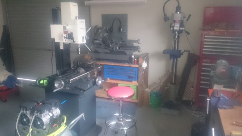
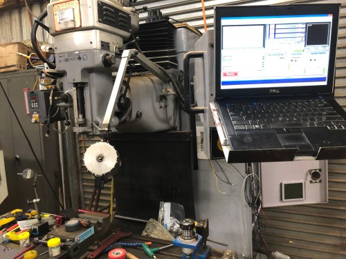
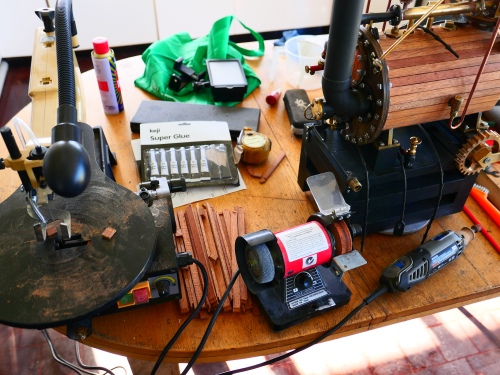
When I did venture back into the workshop, I discovered that my CNC mill was malfunctioning. The Y axis has been a bit unpredictable for quite a while. I found a broken wire and fixed it, but the problem returned. After a previous electronic failure in the Z axis, my CNC expert advisor, Stuart, suggested that I should replace the electronics in a major upgrade. The mill is a solid industrial machine, mechanically in sound condition, and is worth spending some time and money on.
It is a 1997 model, and the memory in the CNC motherboard is a whopping 7k! I was able to get a fair bit done with the 7k, and the situation was improved by linking an external PC, and using V-Carve Pro. But there was a limitation in that the mill is a 2.5 axis machine. Not that I want to use 3 or 4 axes very often, but the lure of improving the mill is irresistible.
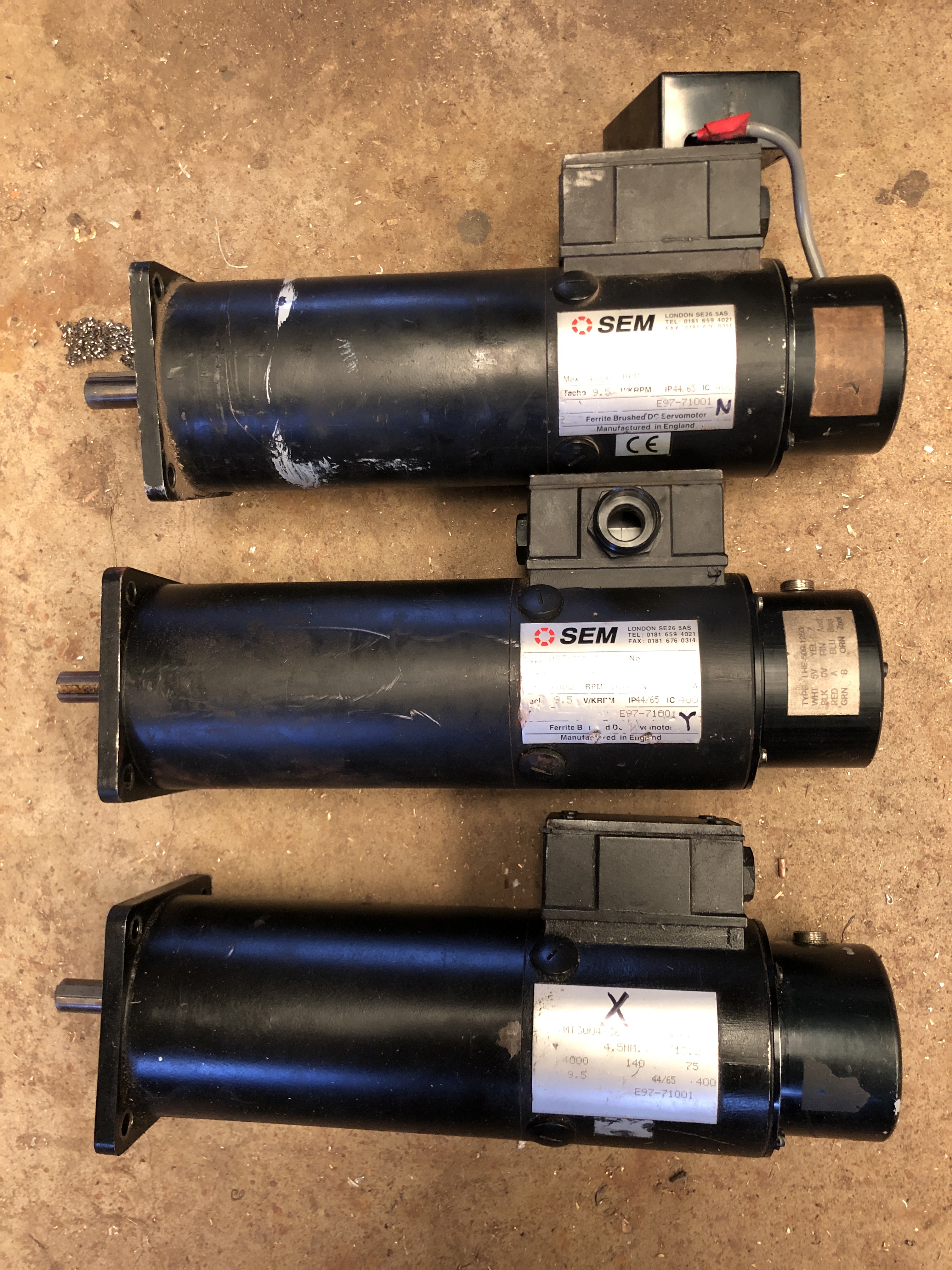
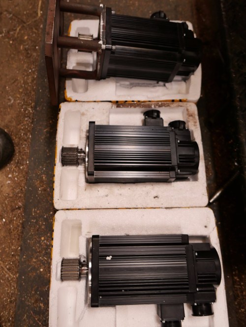
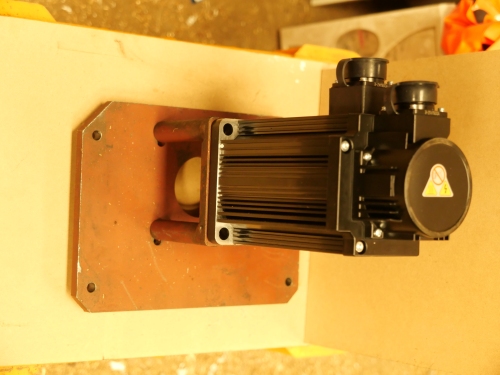
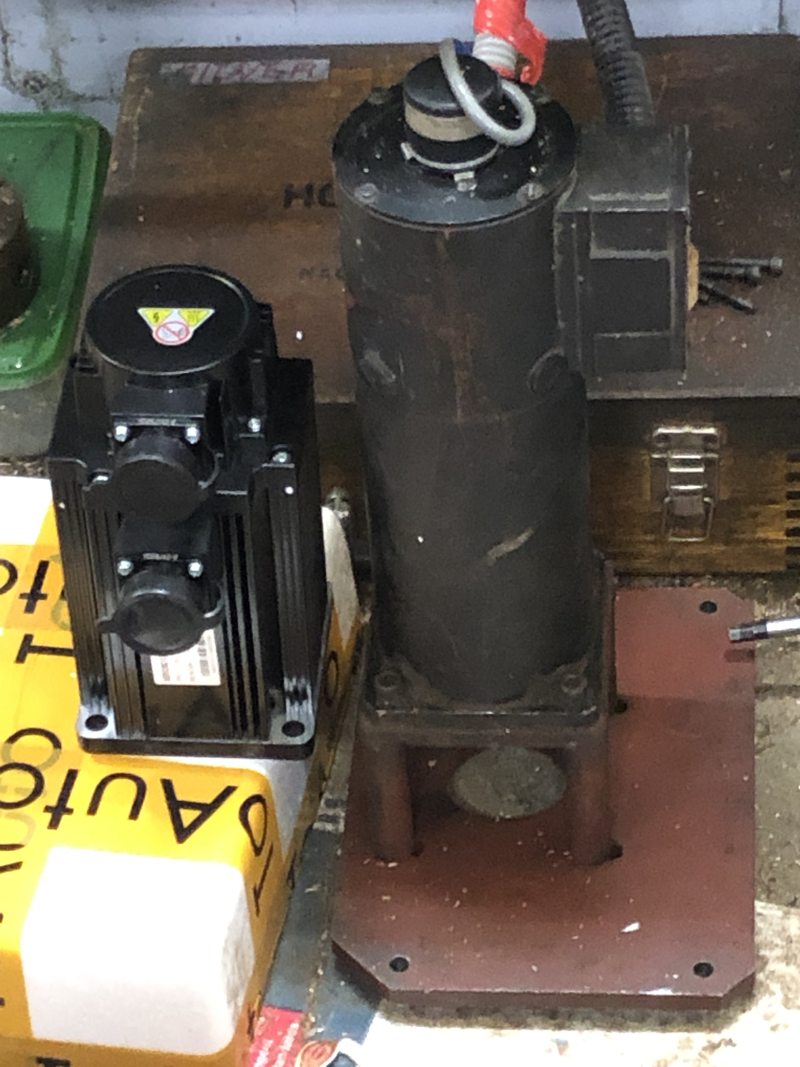
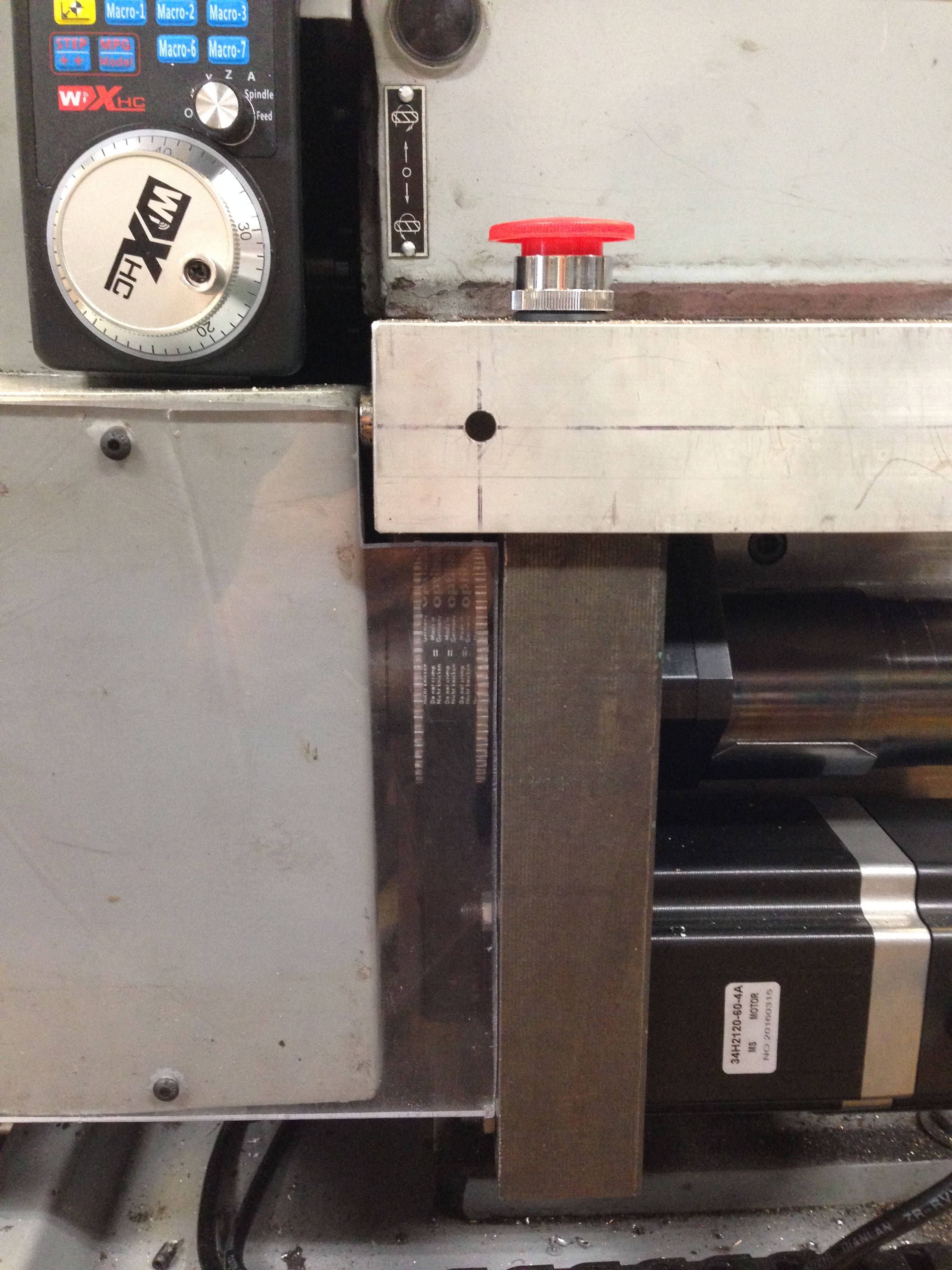
So I am in the process of ordering 3 new servo motors. They will be AC single phase servos, rather than 3 phase motors. I have installed one of these in my small Boxford lathe as a spindle motor, and it has proved to be reliable, compact, powerful and inexpensive (well, fairly inexpensive, comparatively speaking). They have been ordered from China. Cost-wise, the three axis motors will be much less expensive than one of the existing 3 phase servos. On top of that I will need a breakout board, ESS smooth stepper to link to a computer, and various switches, wiring, power supplies etc.
I will document the steps of the rebuild.
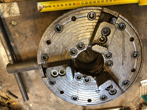
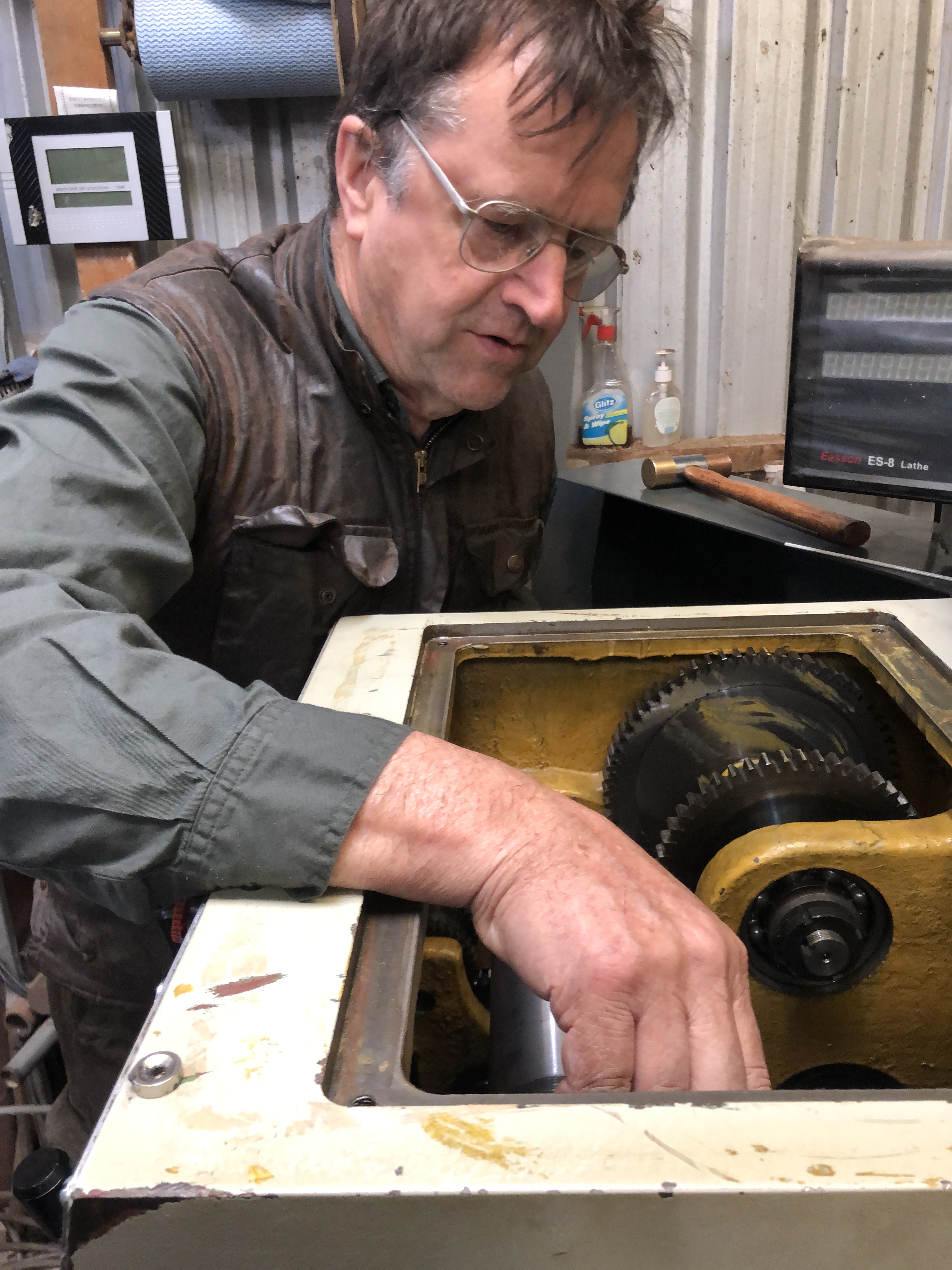
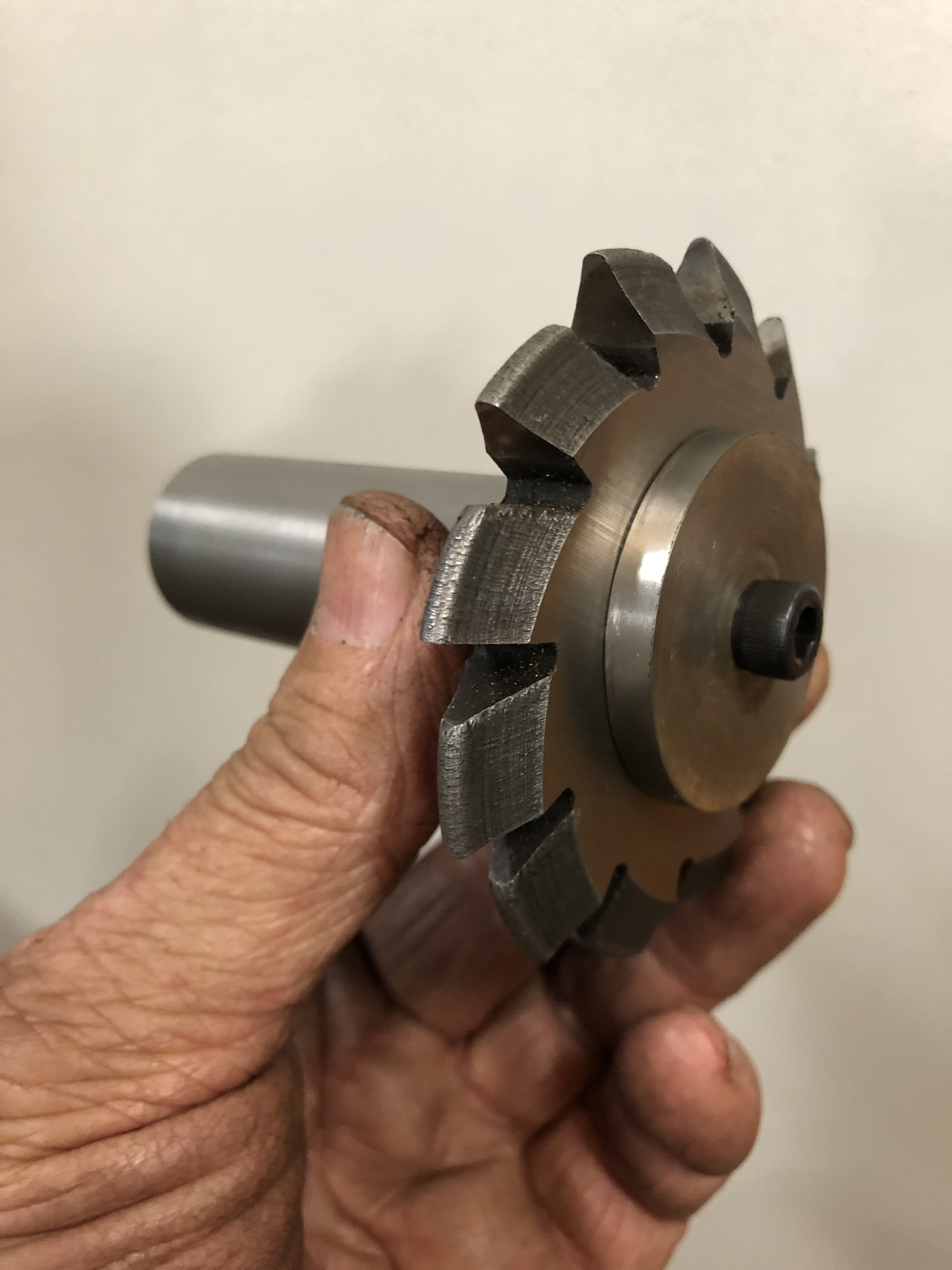
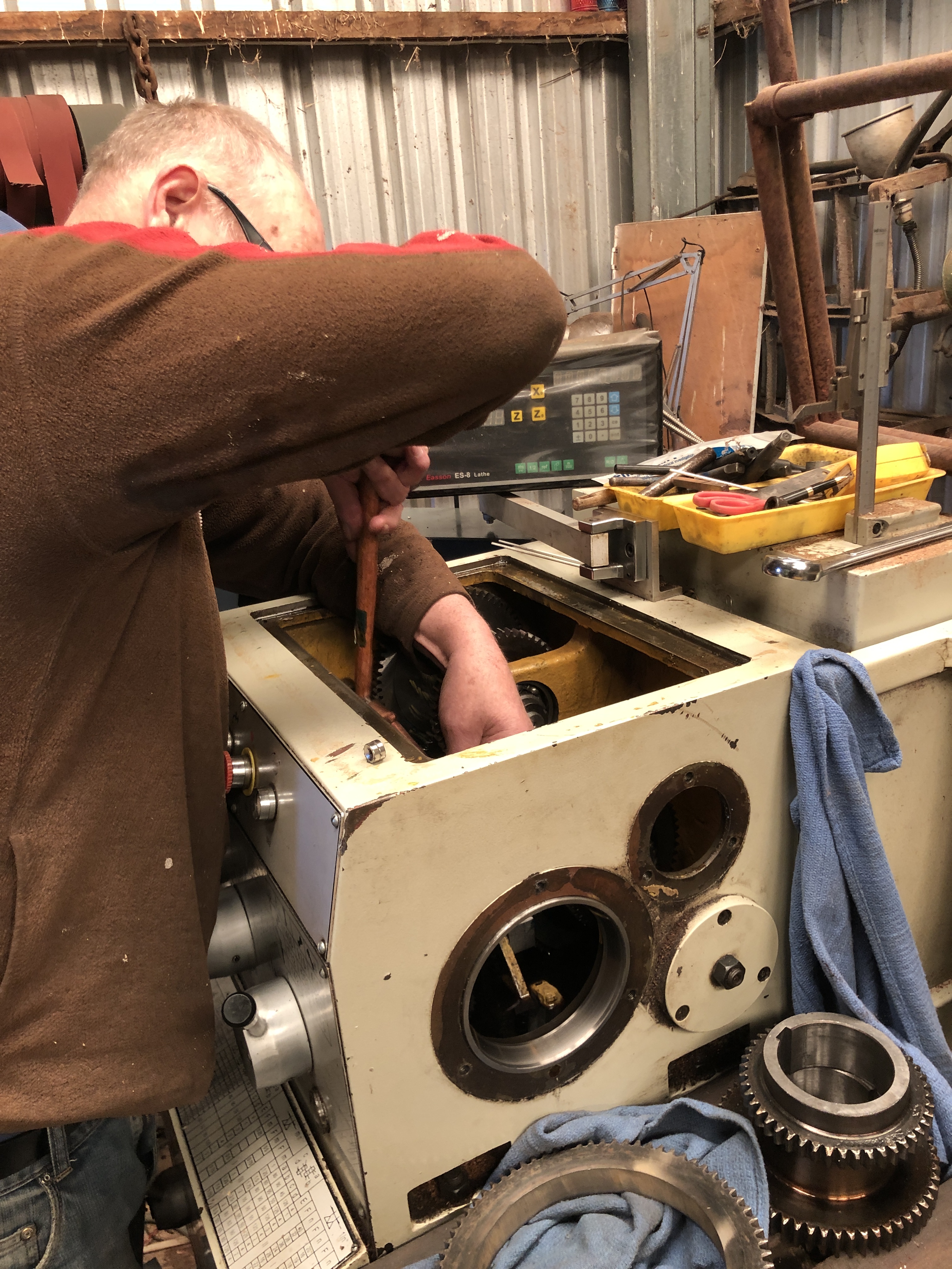
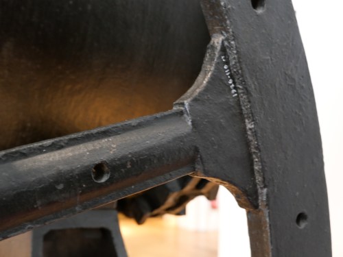
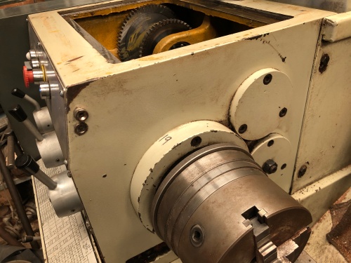
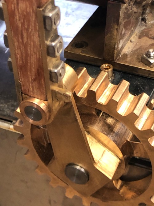
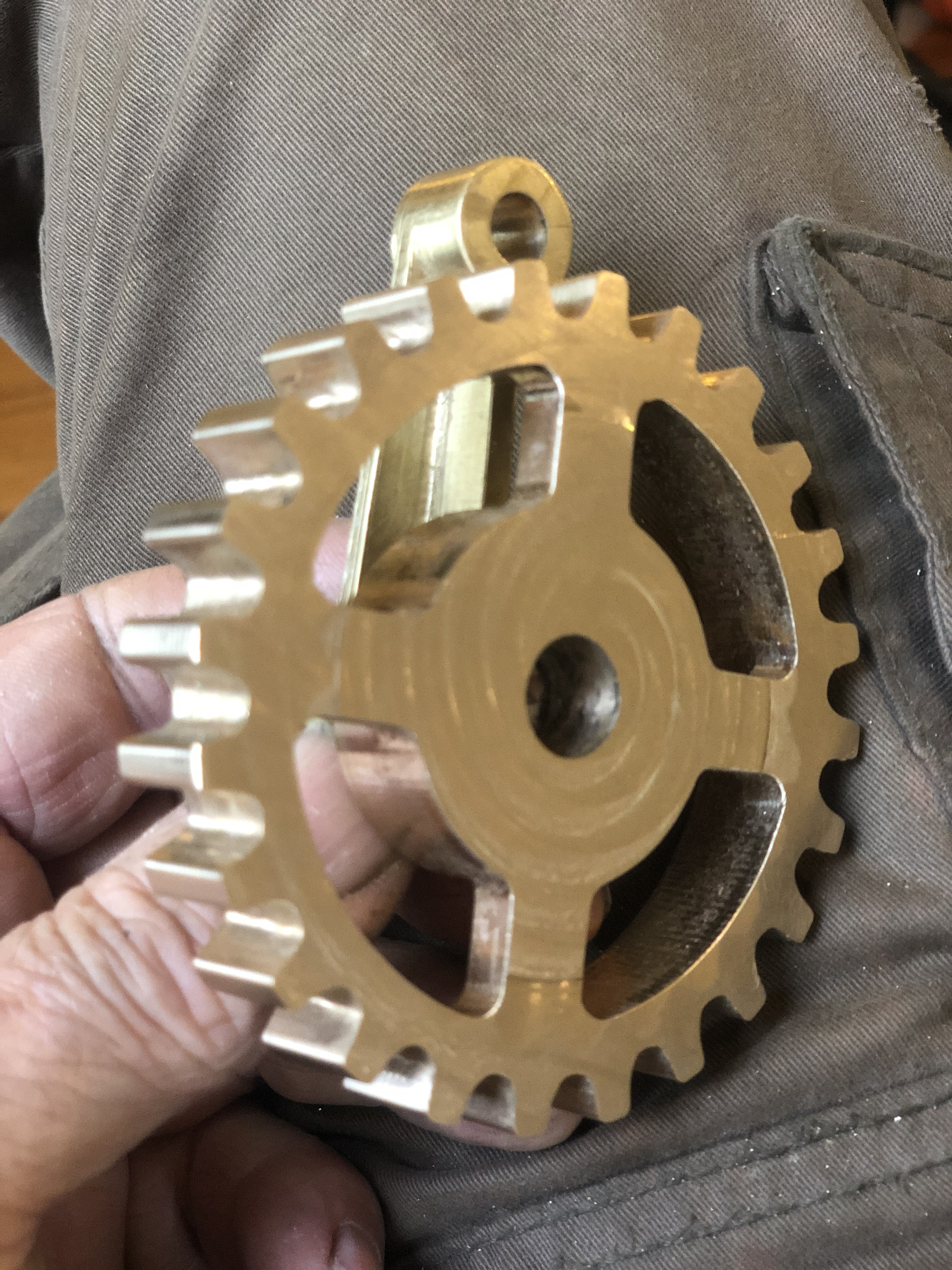
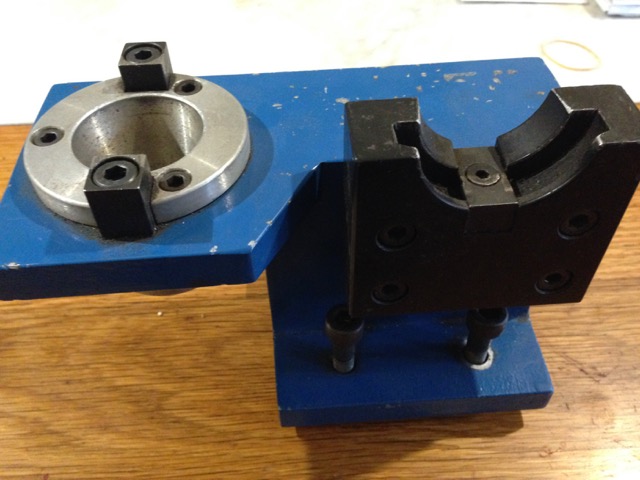
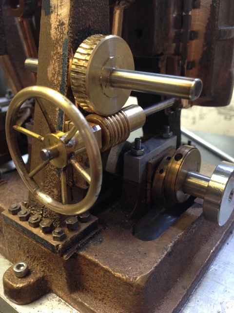
But the item that I was getting to, was hooking up my rotary table to CNC. I had expected to pick up a new gear for my big lathe on my return from the UK, to replace the one with the broken tooth. I was pretty annoyed to learn that the gear maker had not done the job, and worse still he had not notified me that it had not been done. Since he never answers the telephone, I drove to the factory, expecting to pick up the new gear, as arranged and promised, to be met with apologies and excuses. Long story, I have decided to make the gear myself.
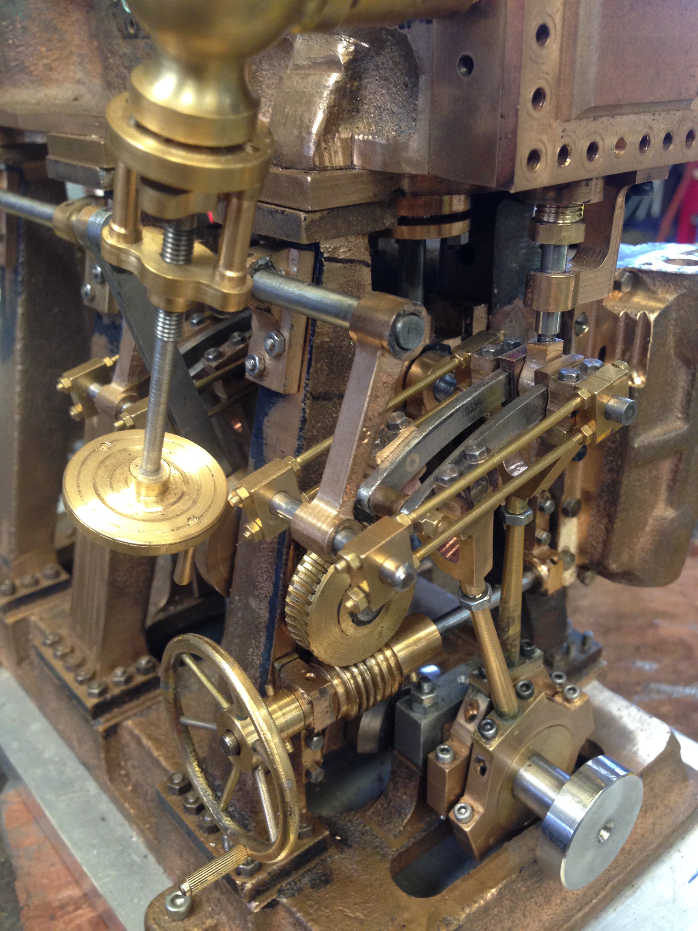
It has 77 teeth, an unusual number for a gear, which means that it has to be made, not purchased off the shelf. I have a dividing plate with 77 teeth, but I could see plenty of potential for making mistakes using that, so I elected to finish the CNC conversion of the rotary table which I had started last year. The mechanical aspects had been finished. All that was required were the electronic hookups. Fortunately for me, I have a friend who is an expert at these.


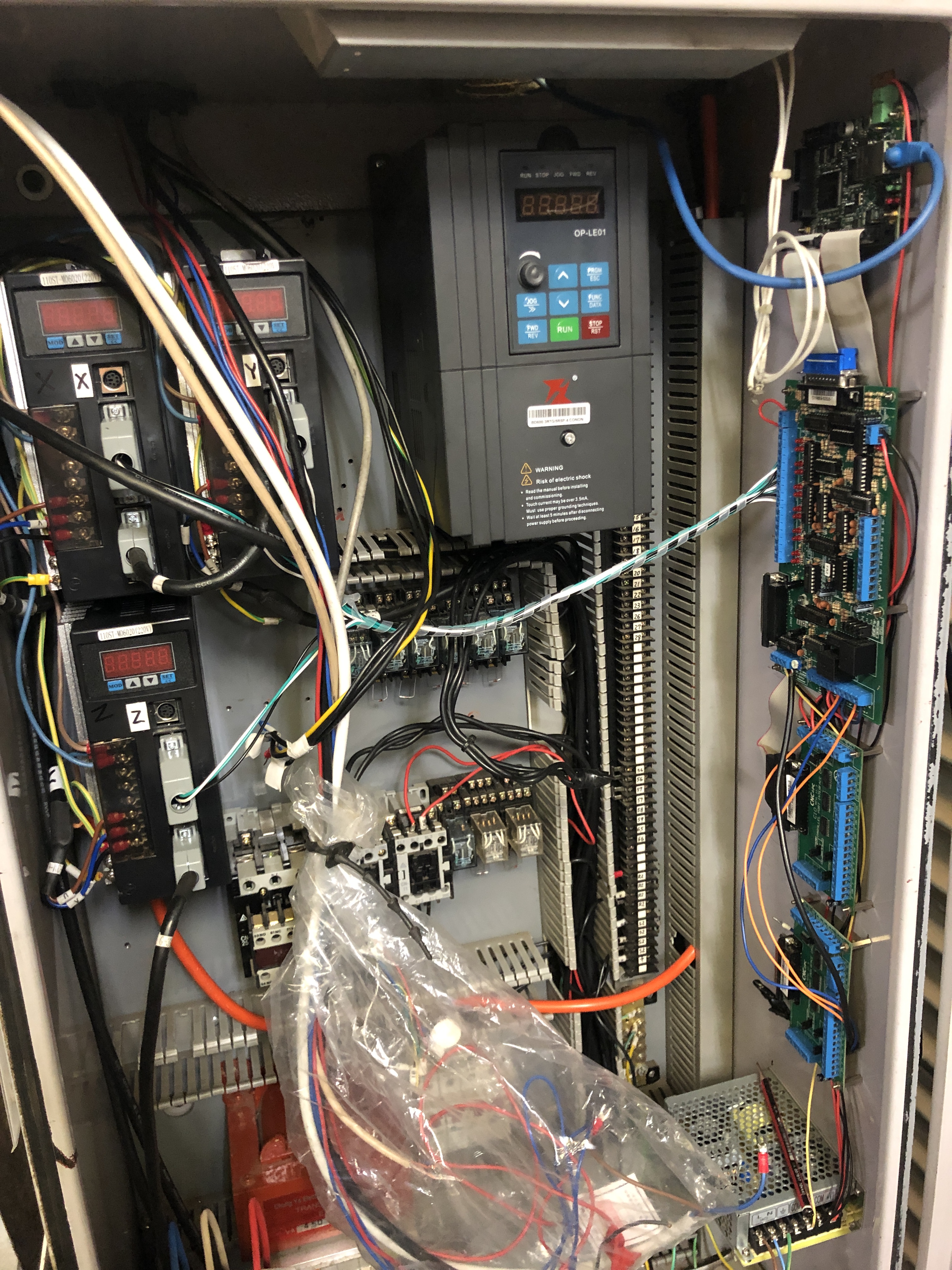
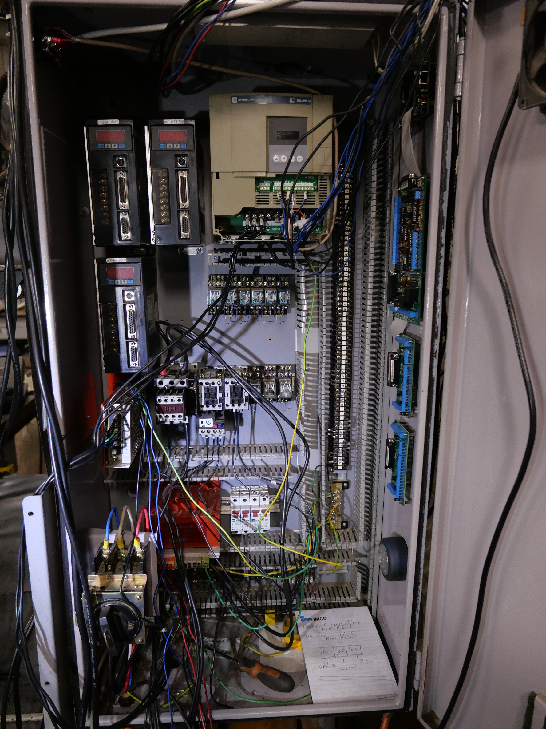
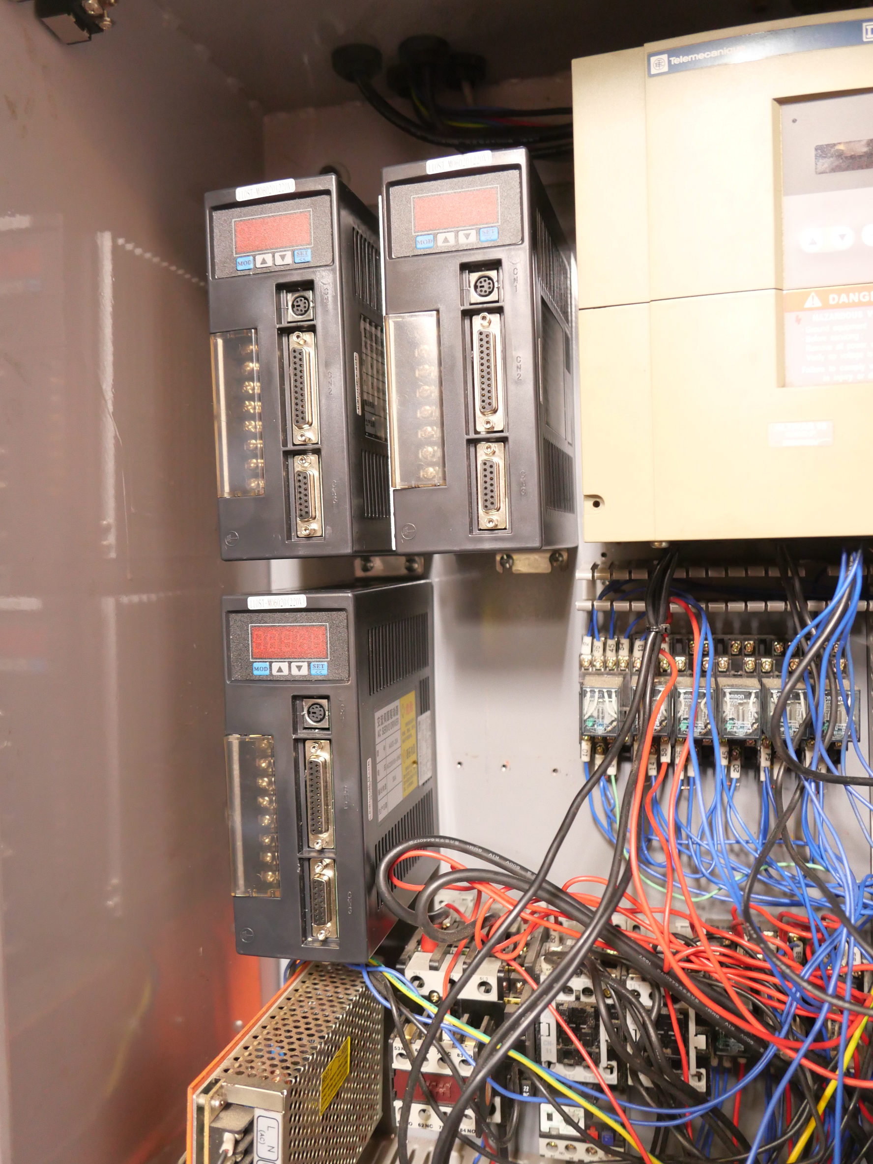
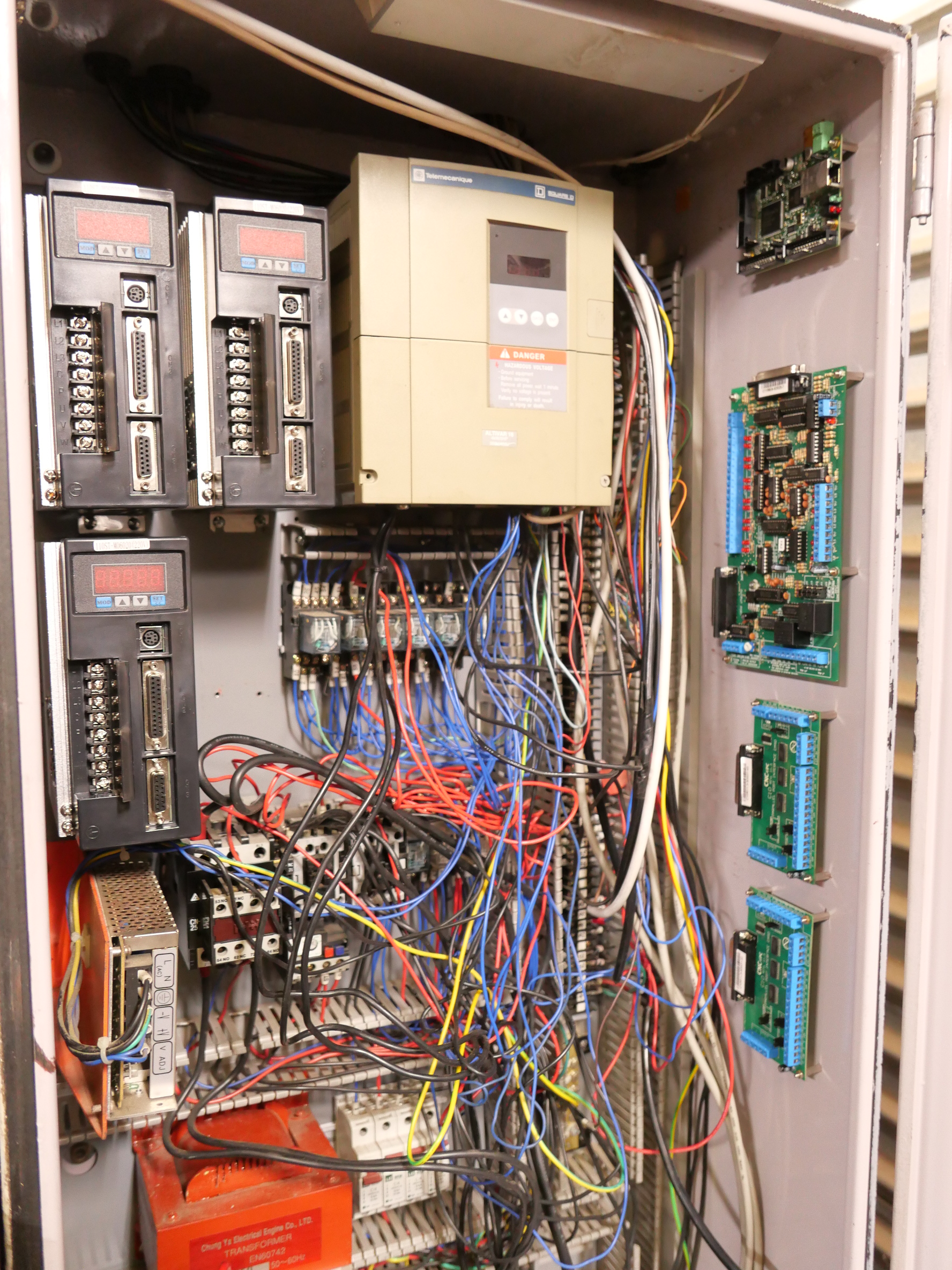
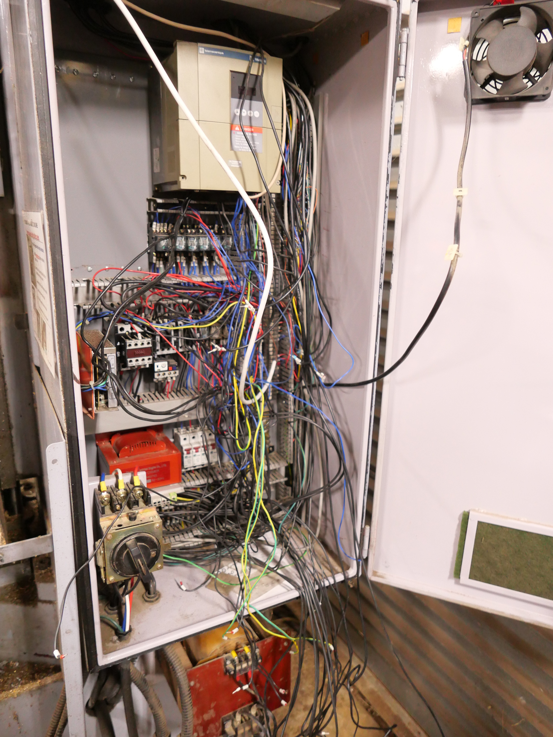
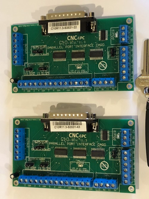
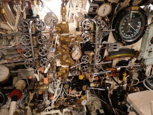
Looks complicated and messy. Much better with the doors closed. The rotary table Geckodrive is the one on the left. The 2 on the right are for the lathe. The black white and green wires 8,9,10, are from the breakout board. The black and red 1 and 2 are from the 48v power supply, and the stepper motor power is from Windings A and B, 3,4,5,6, in the thick white wire.
I confess that I have little understanding of the wiring. Stuart had it hooked up in under an hour. A bit longer configuring and tweaking Mach 3, and it was working. The extra Geckodrive, and some wires were the only extra components required to make the electronic connections.
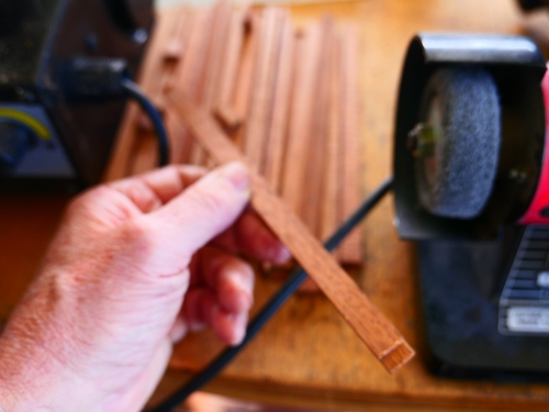
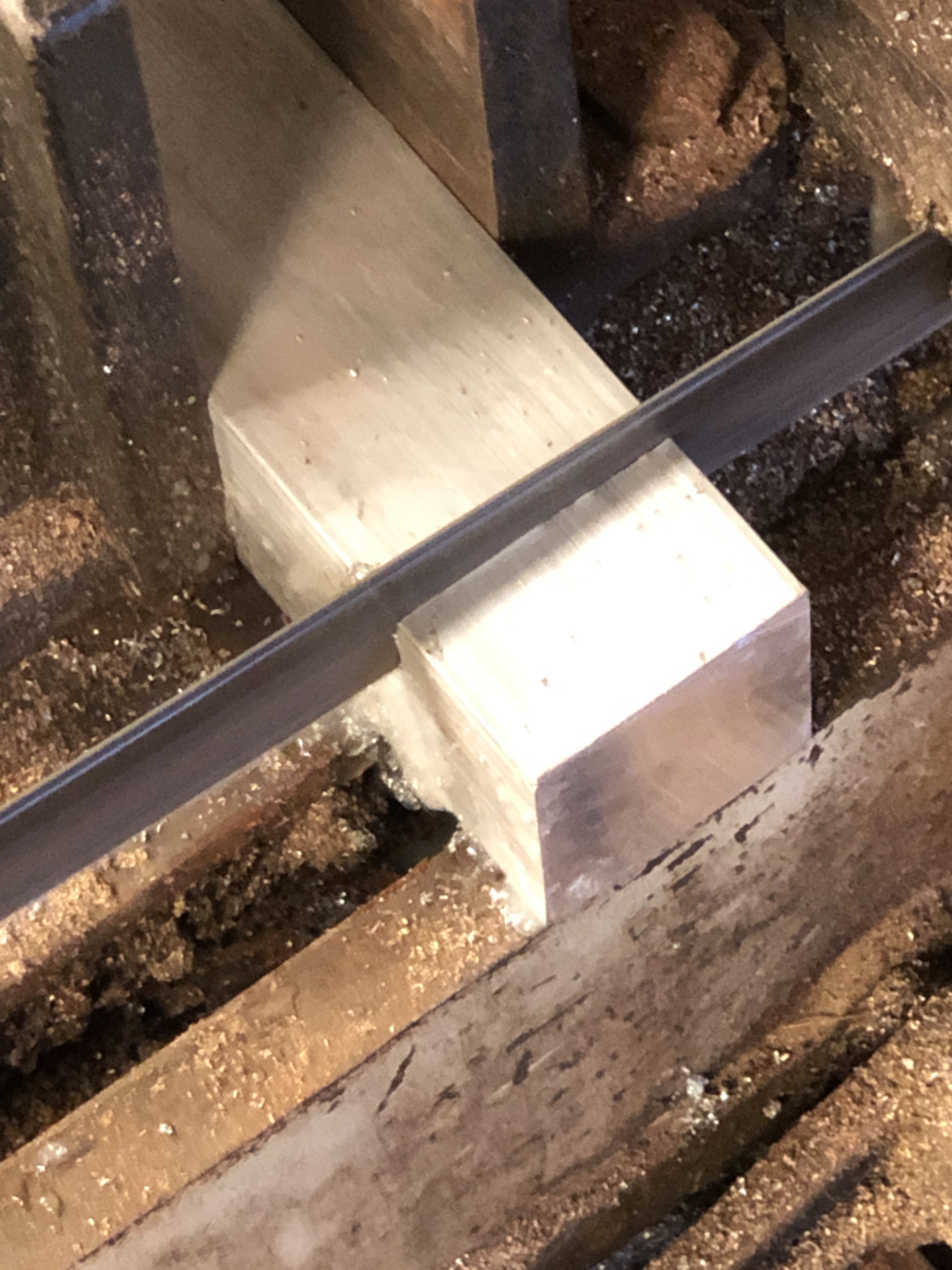
I shot a video of it working, with giving a commentary. But it is so bad that I will reshoot it, and add it to this post in a day or 2. Sorry. Not done yet. But I have been busy preparing the blank for cutting a new gear.
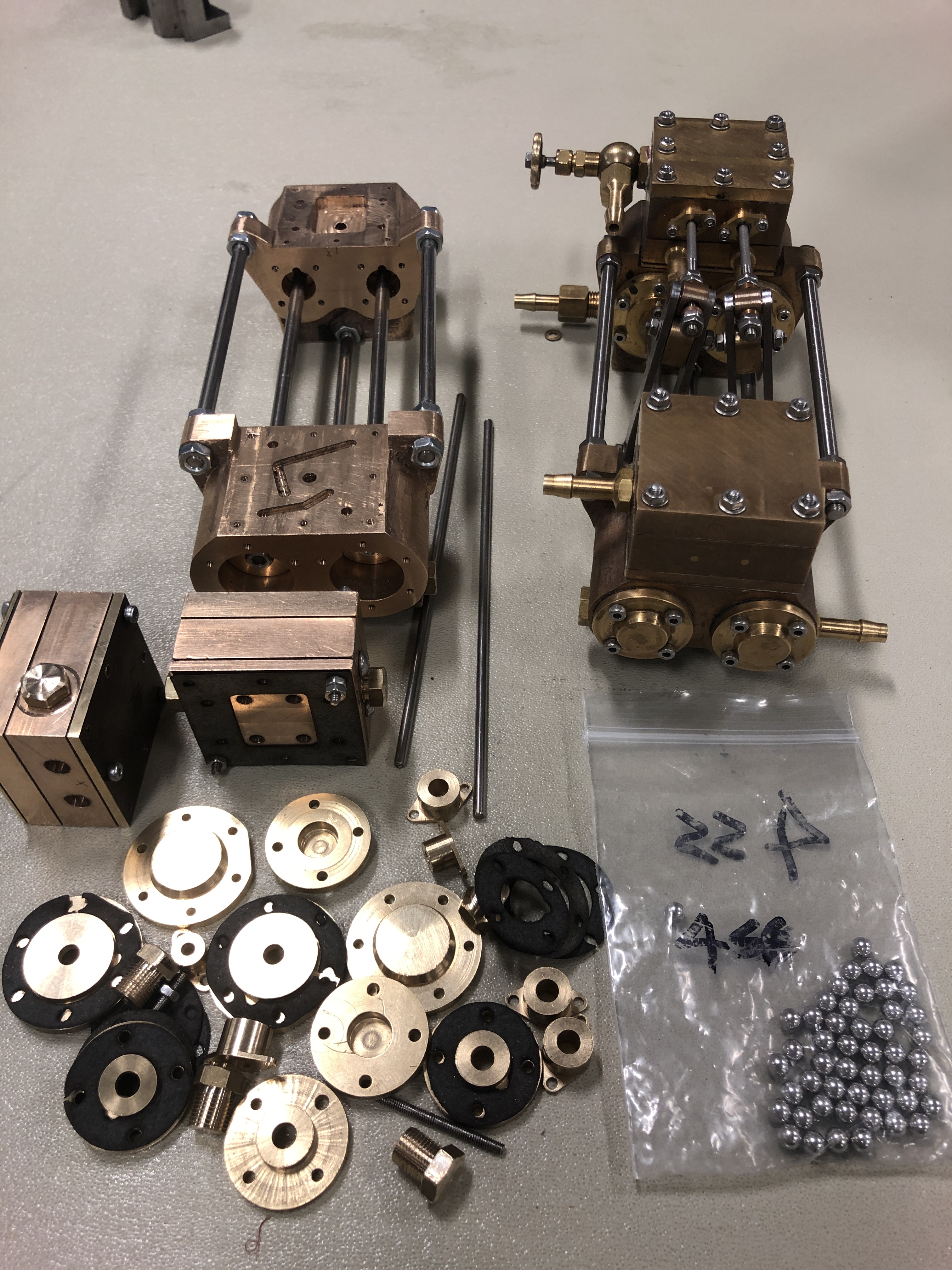
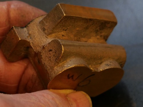
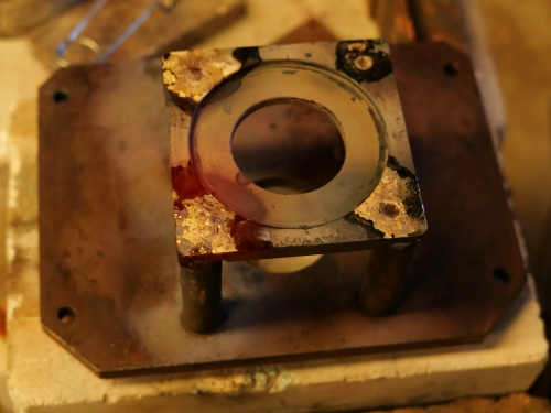
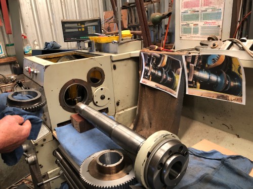
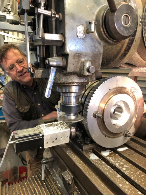
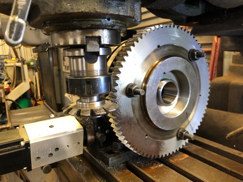
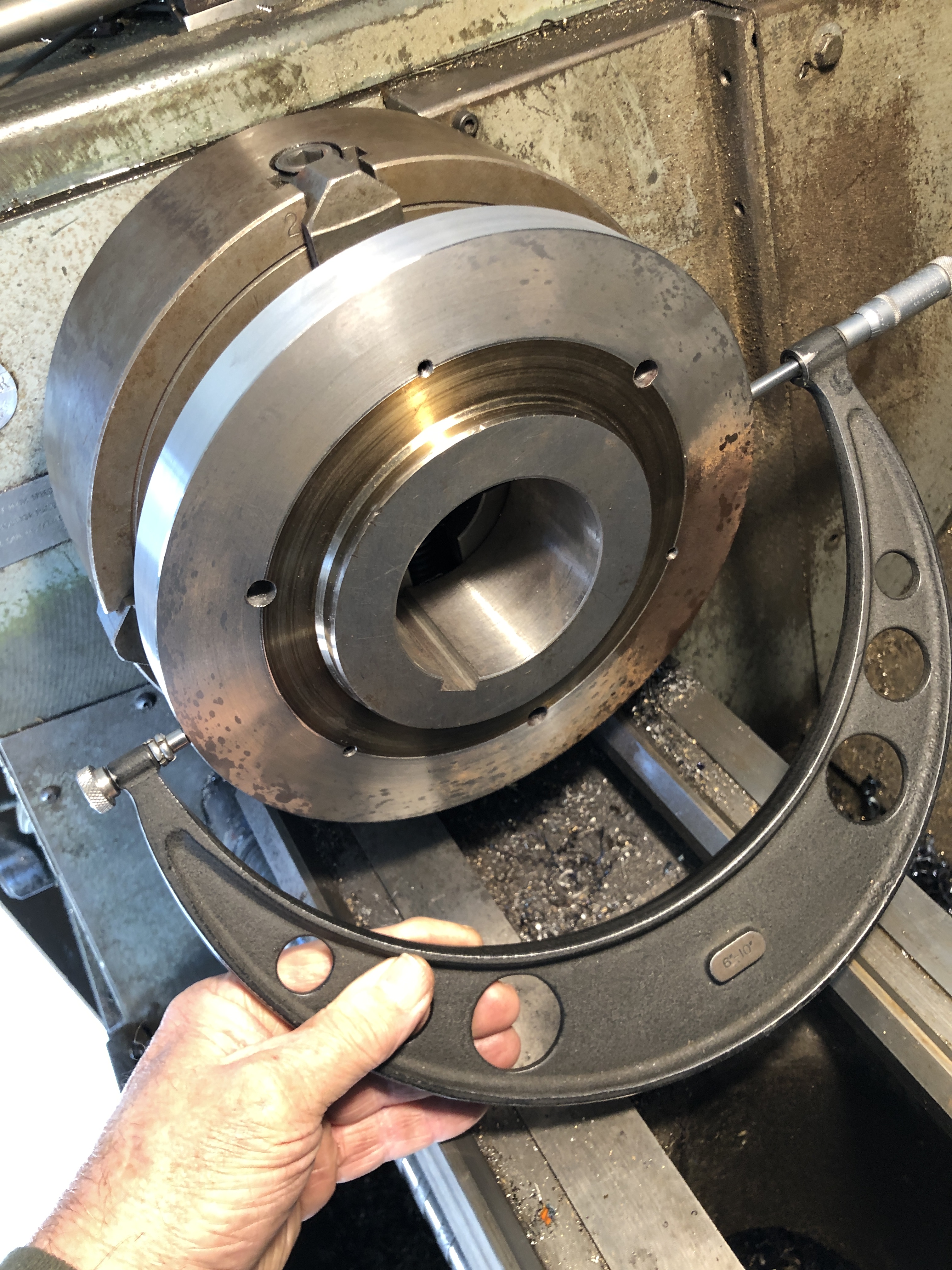
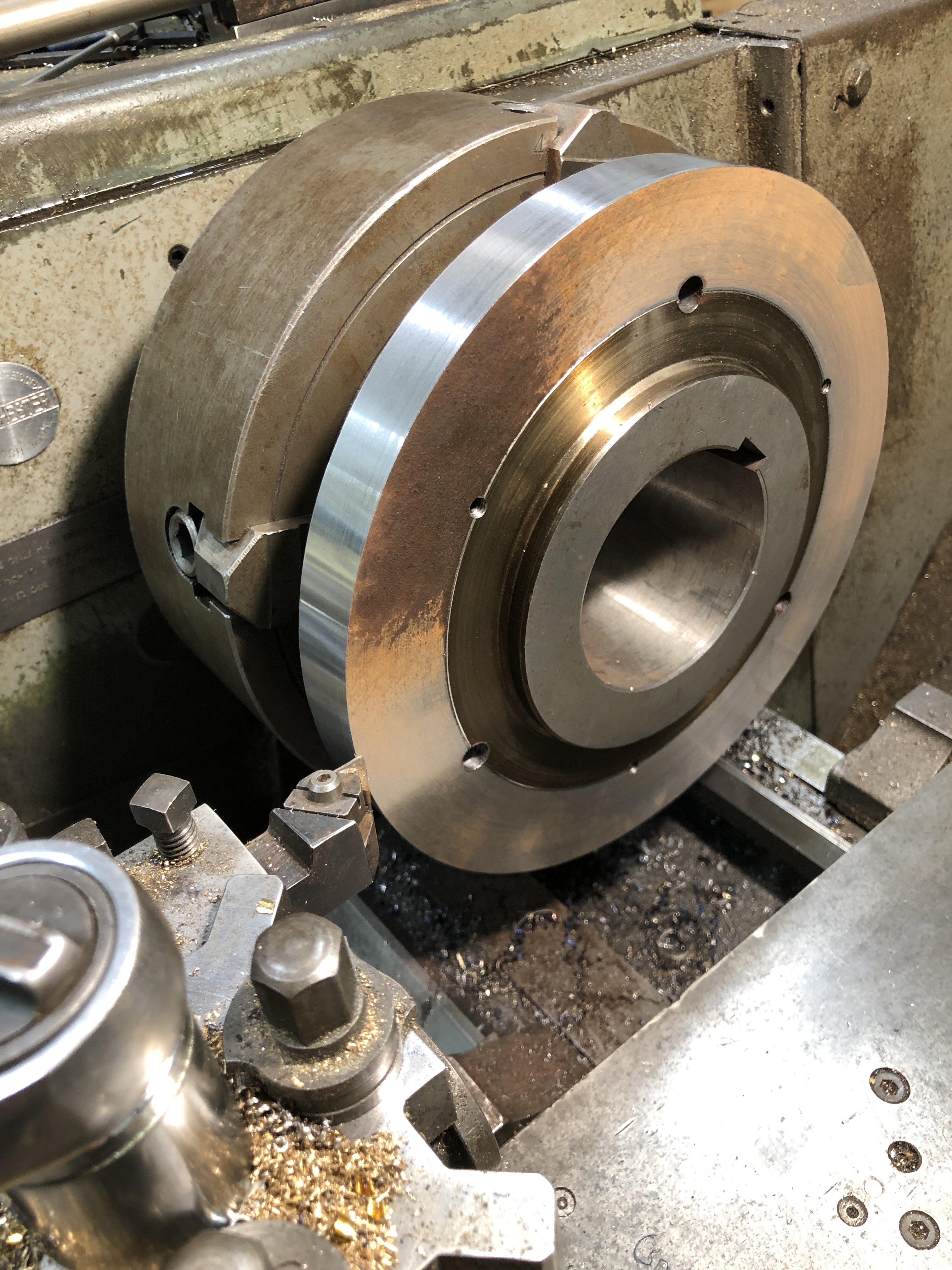
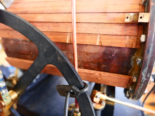
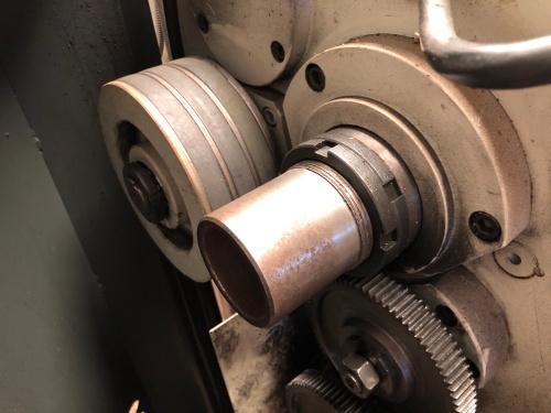
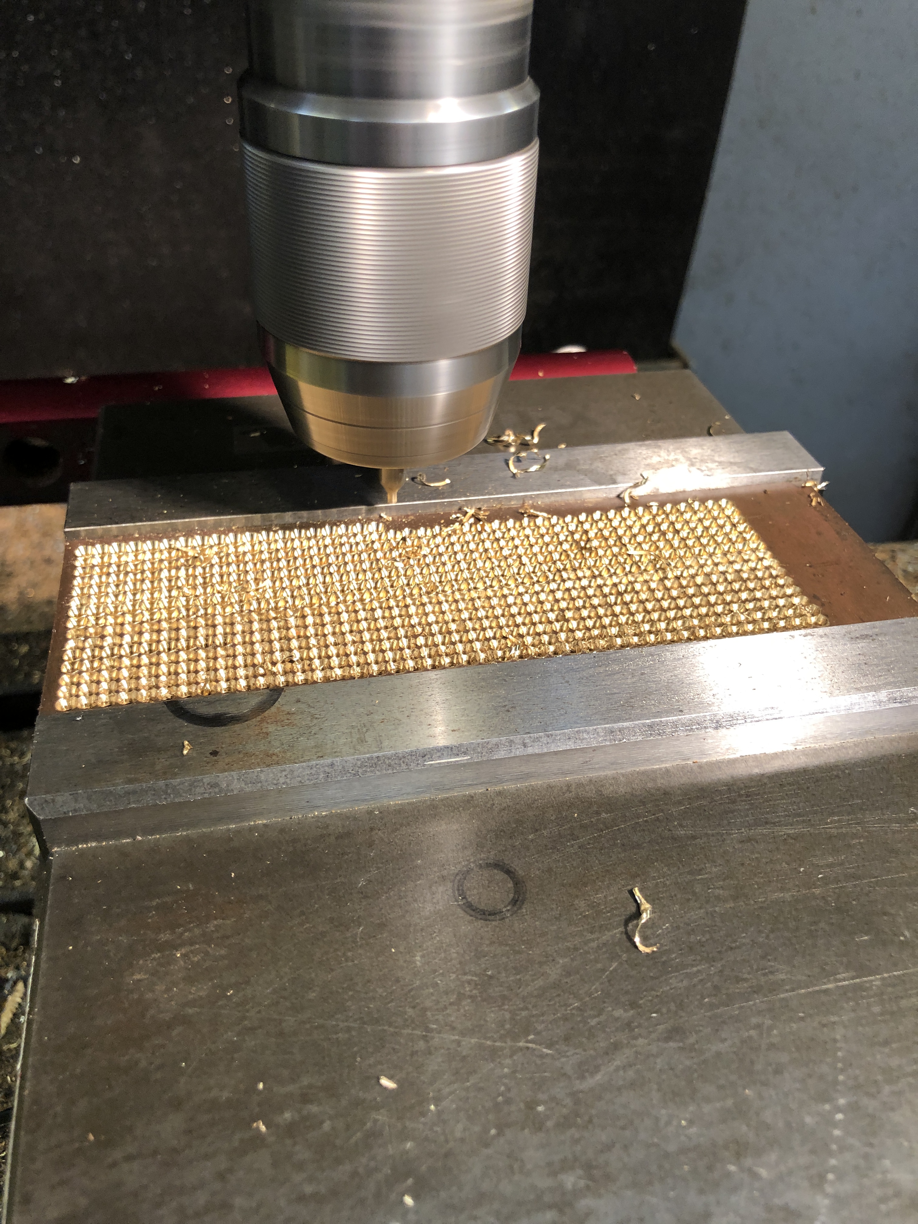
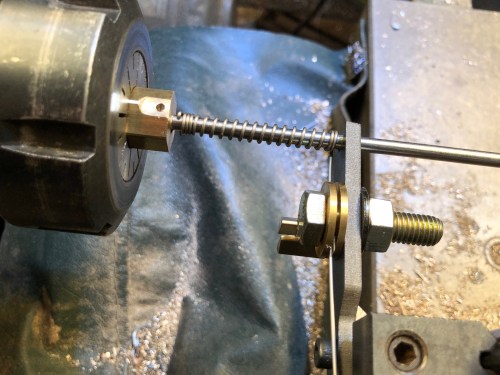
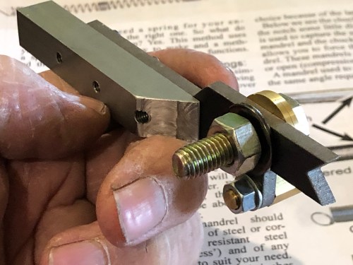
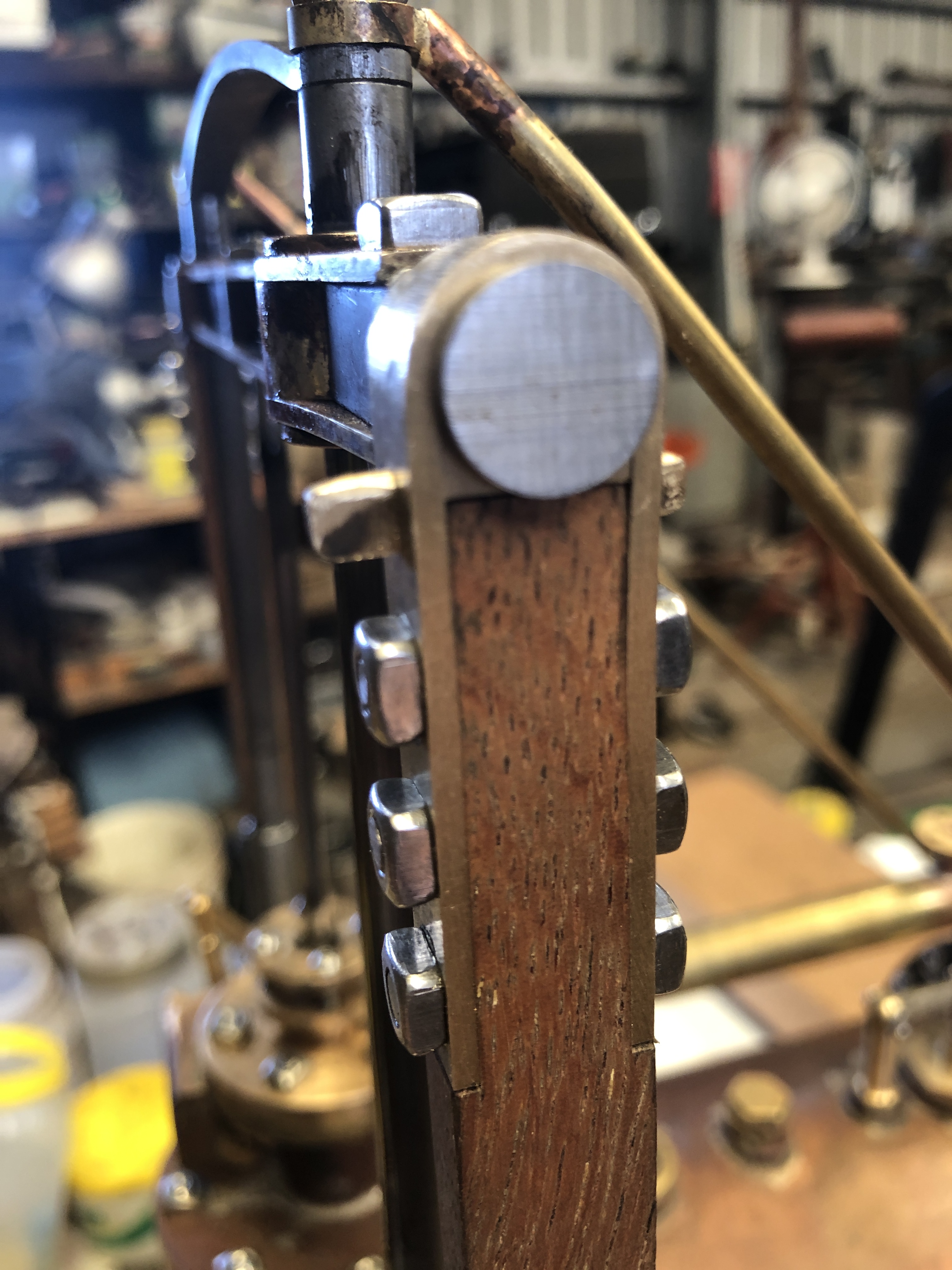
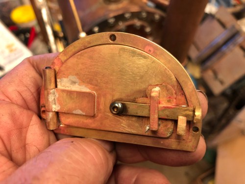
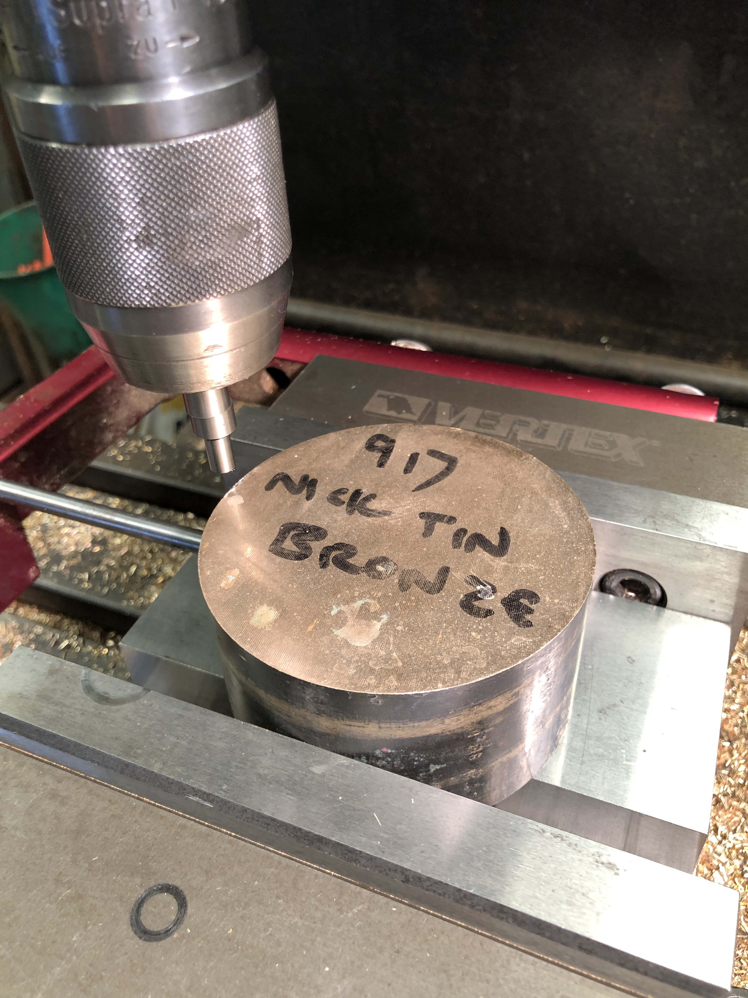
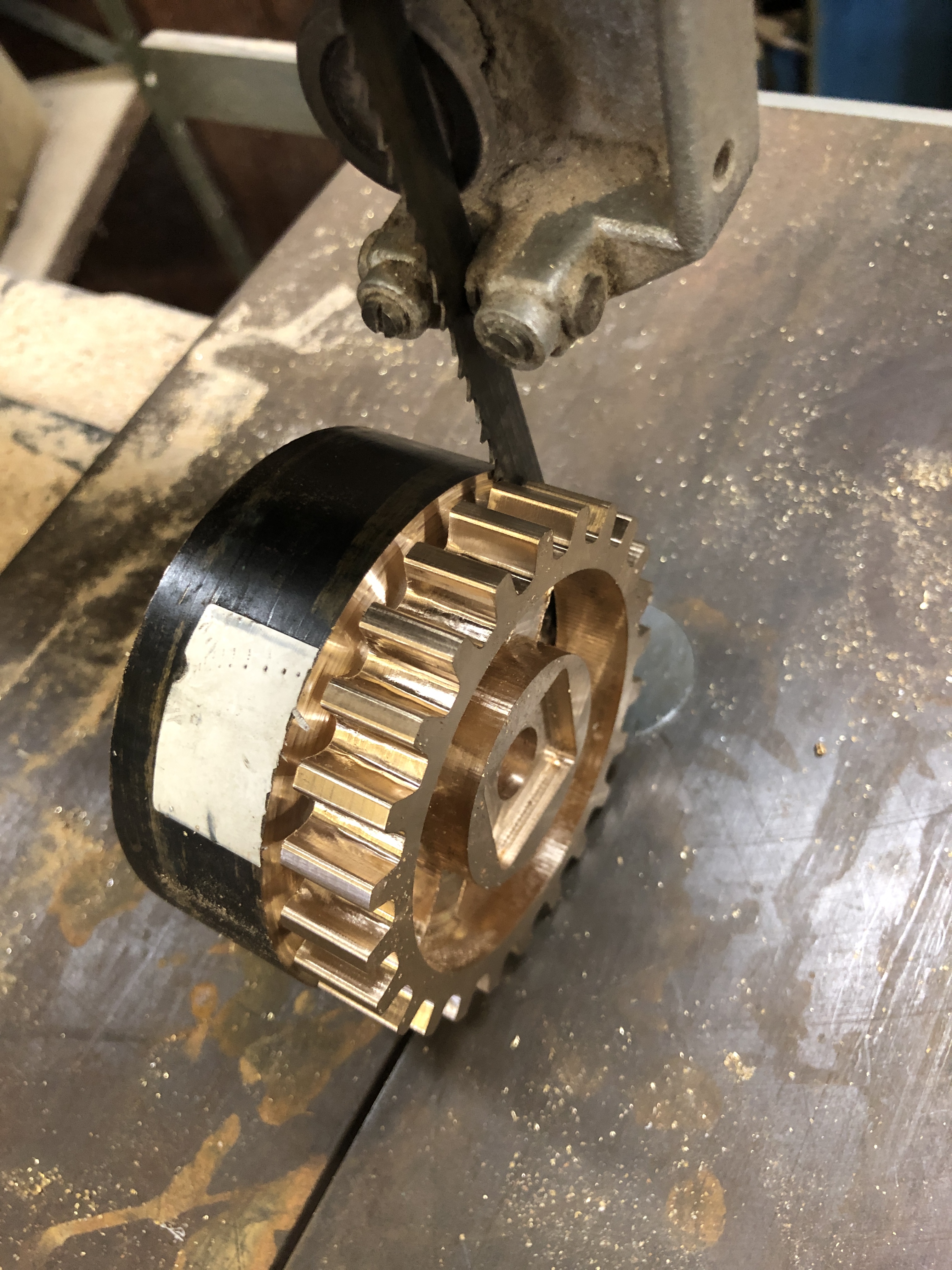
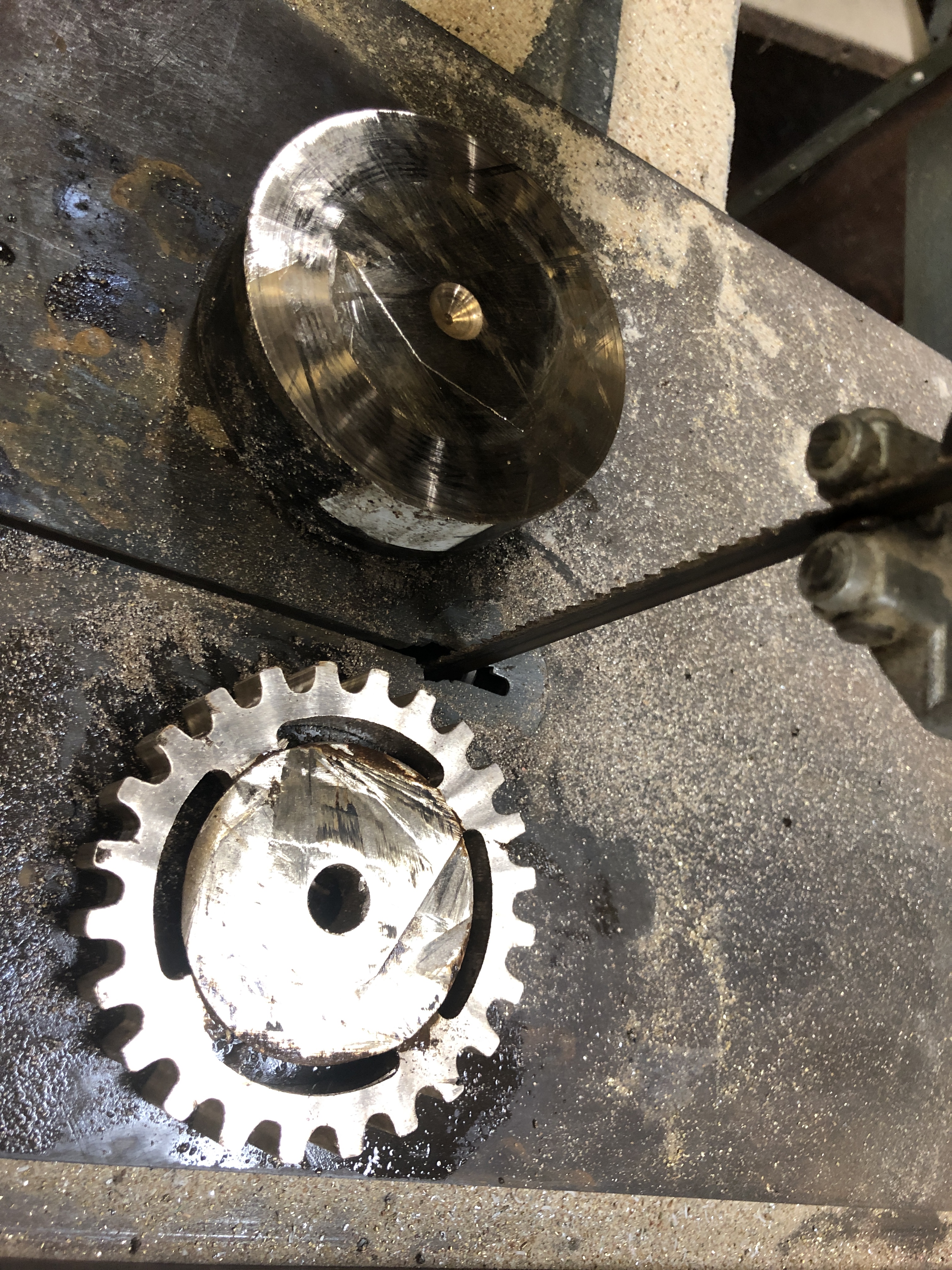
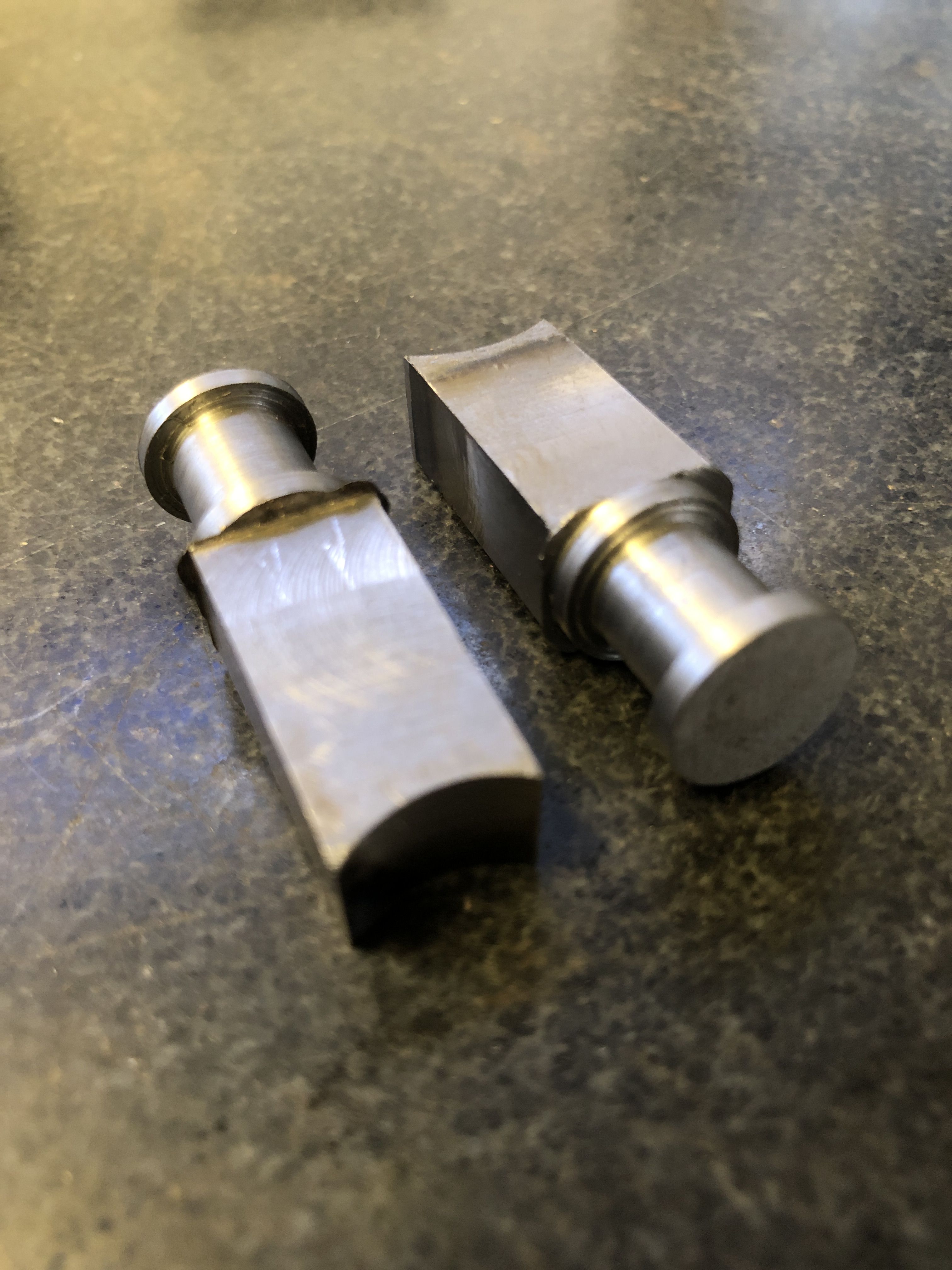
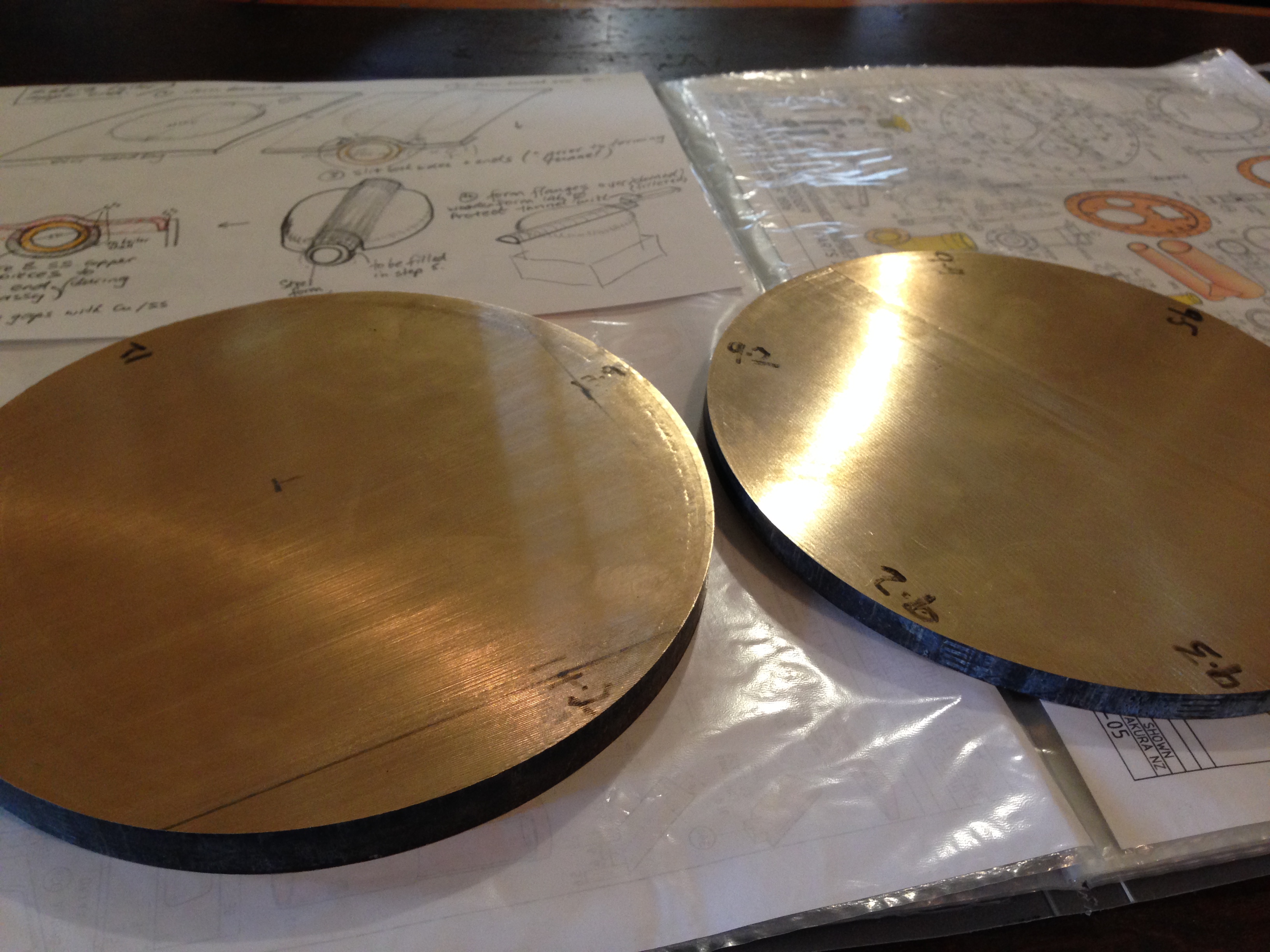
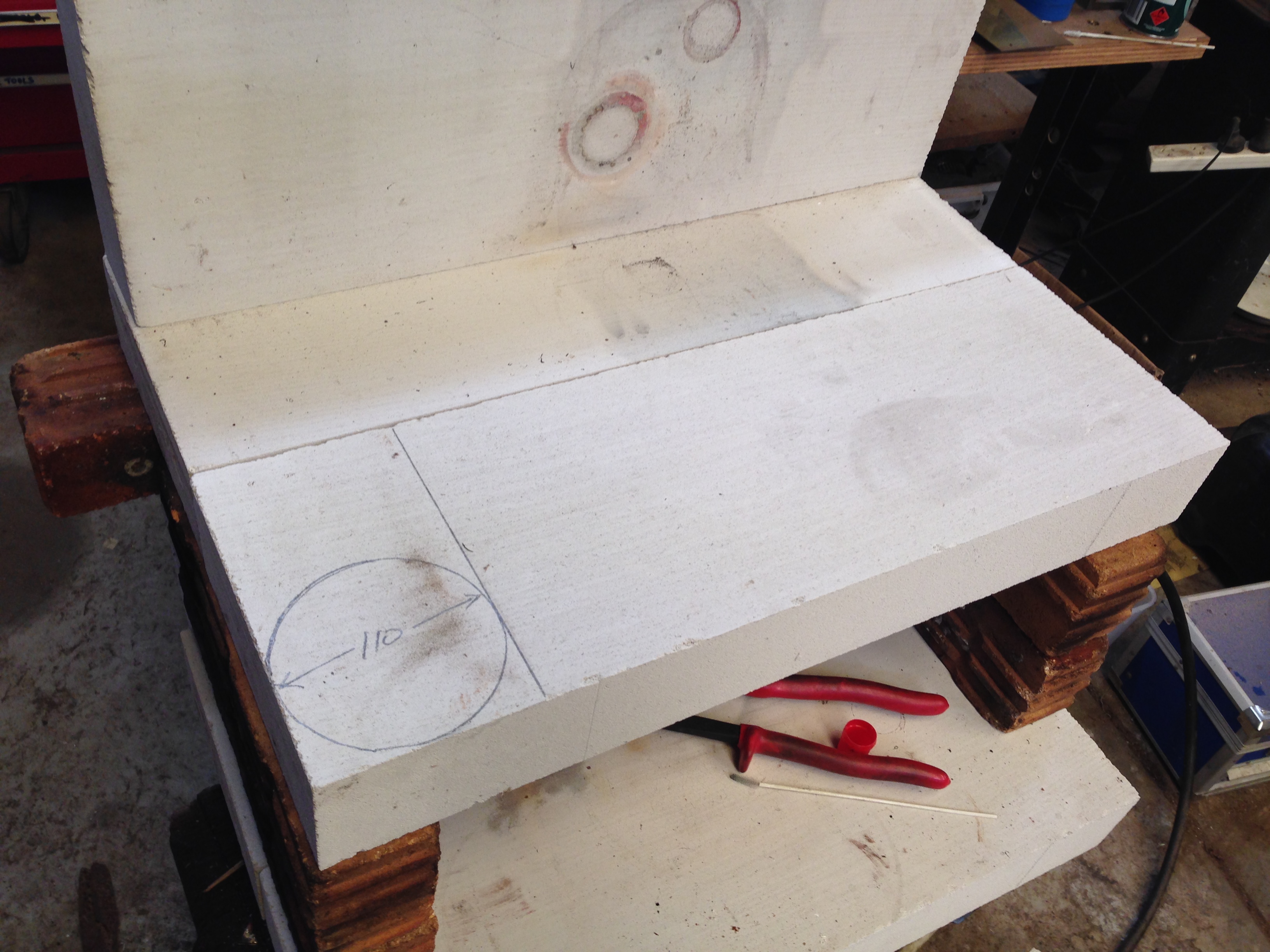
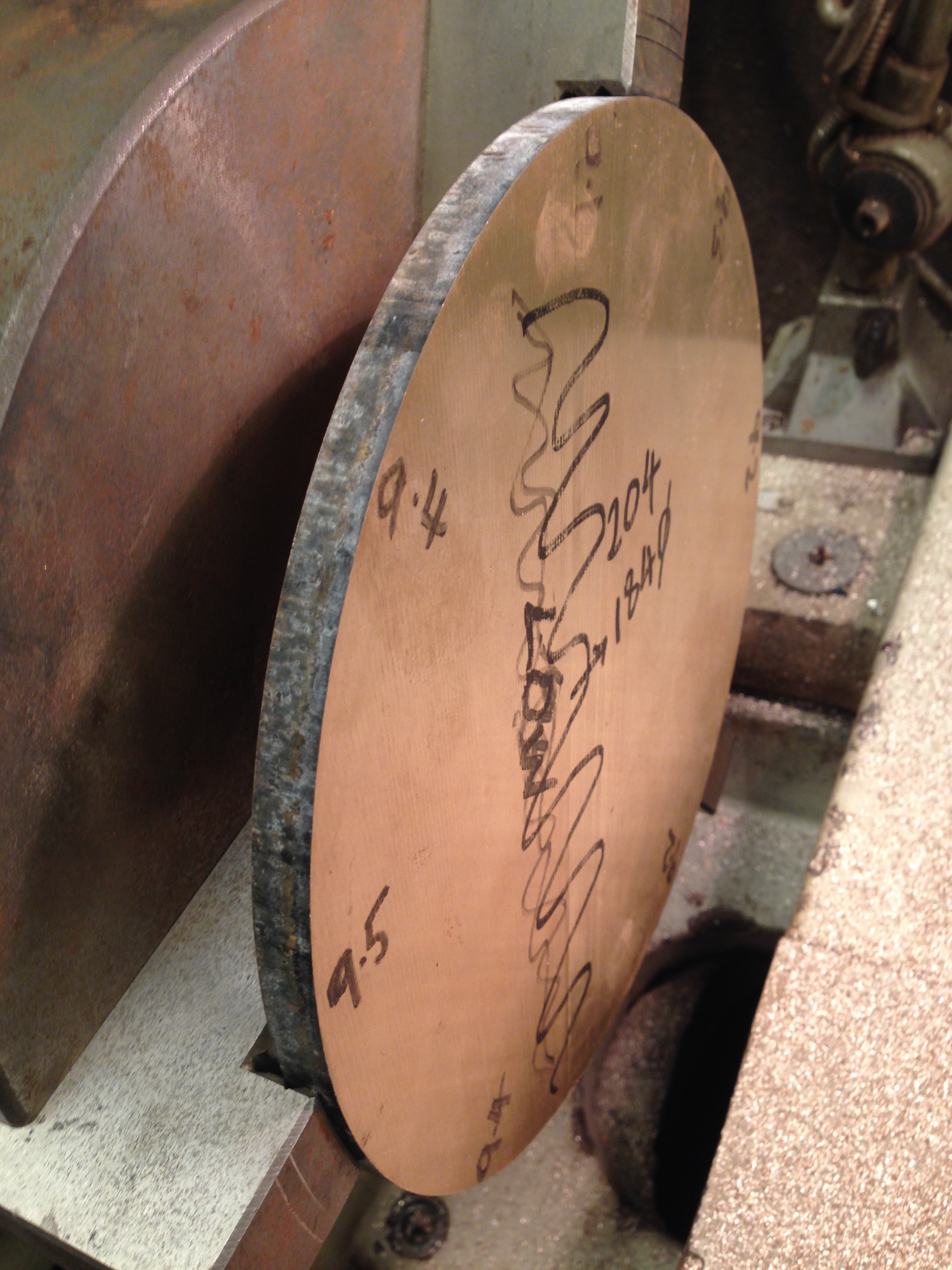
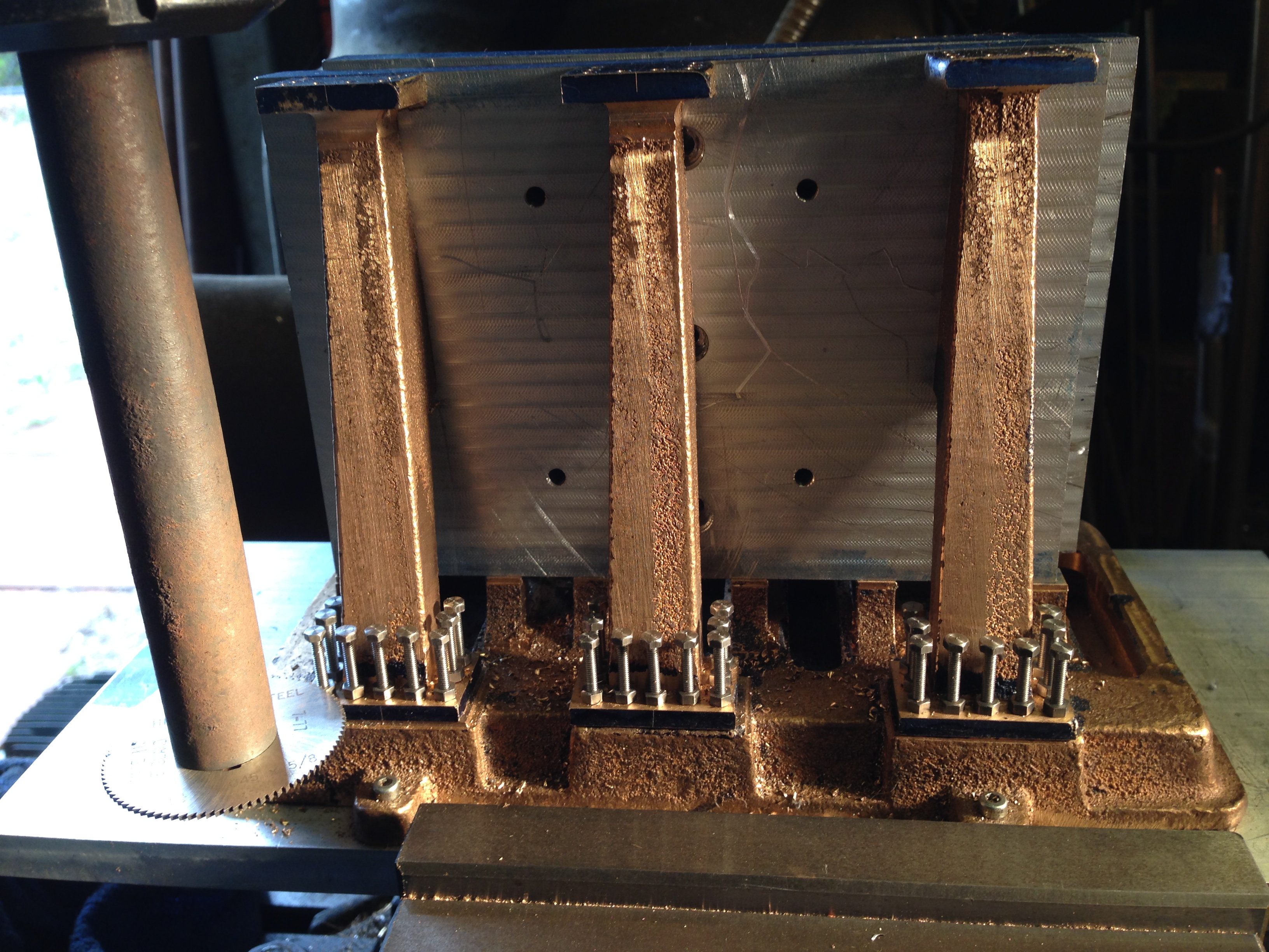
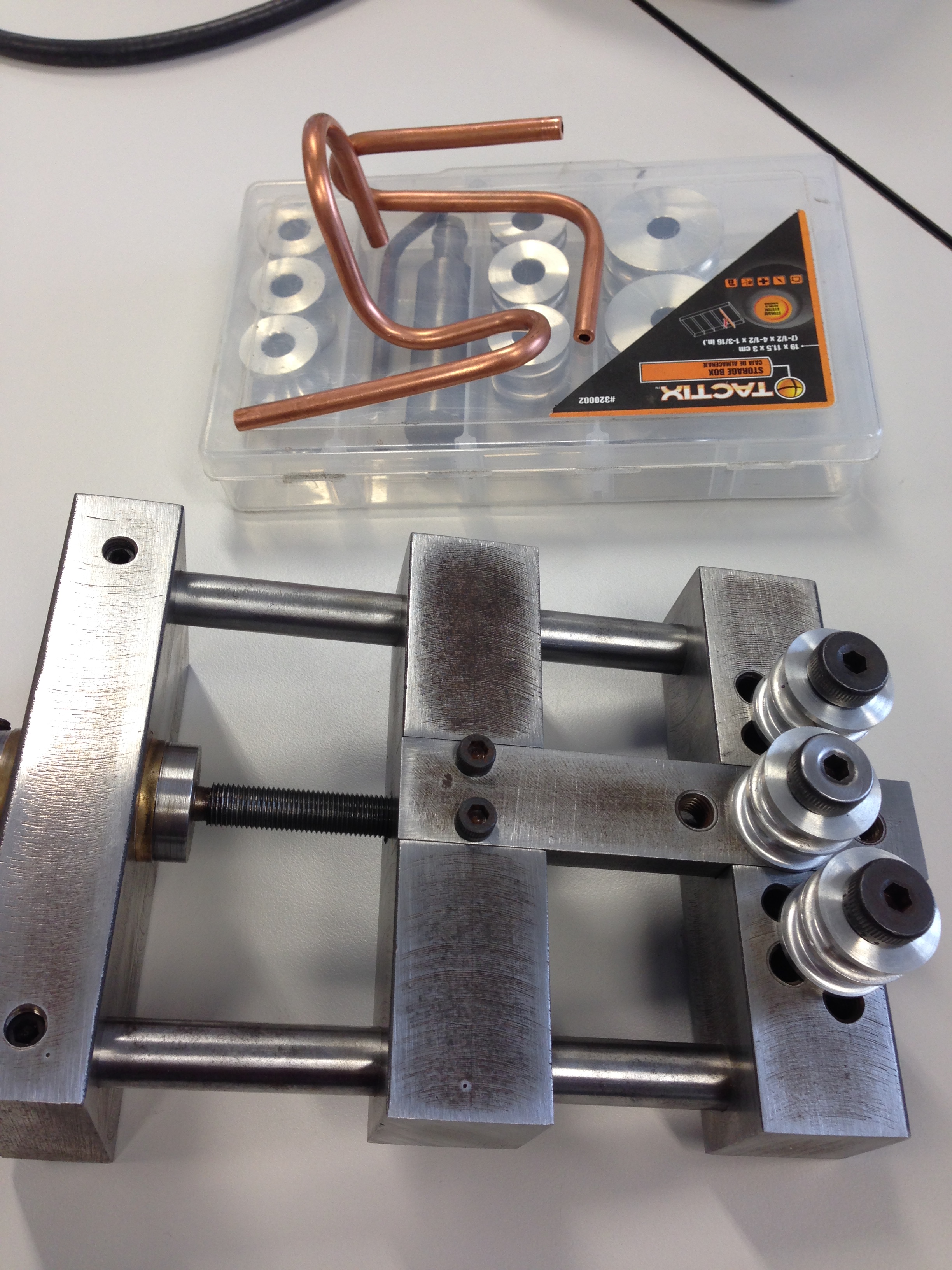
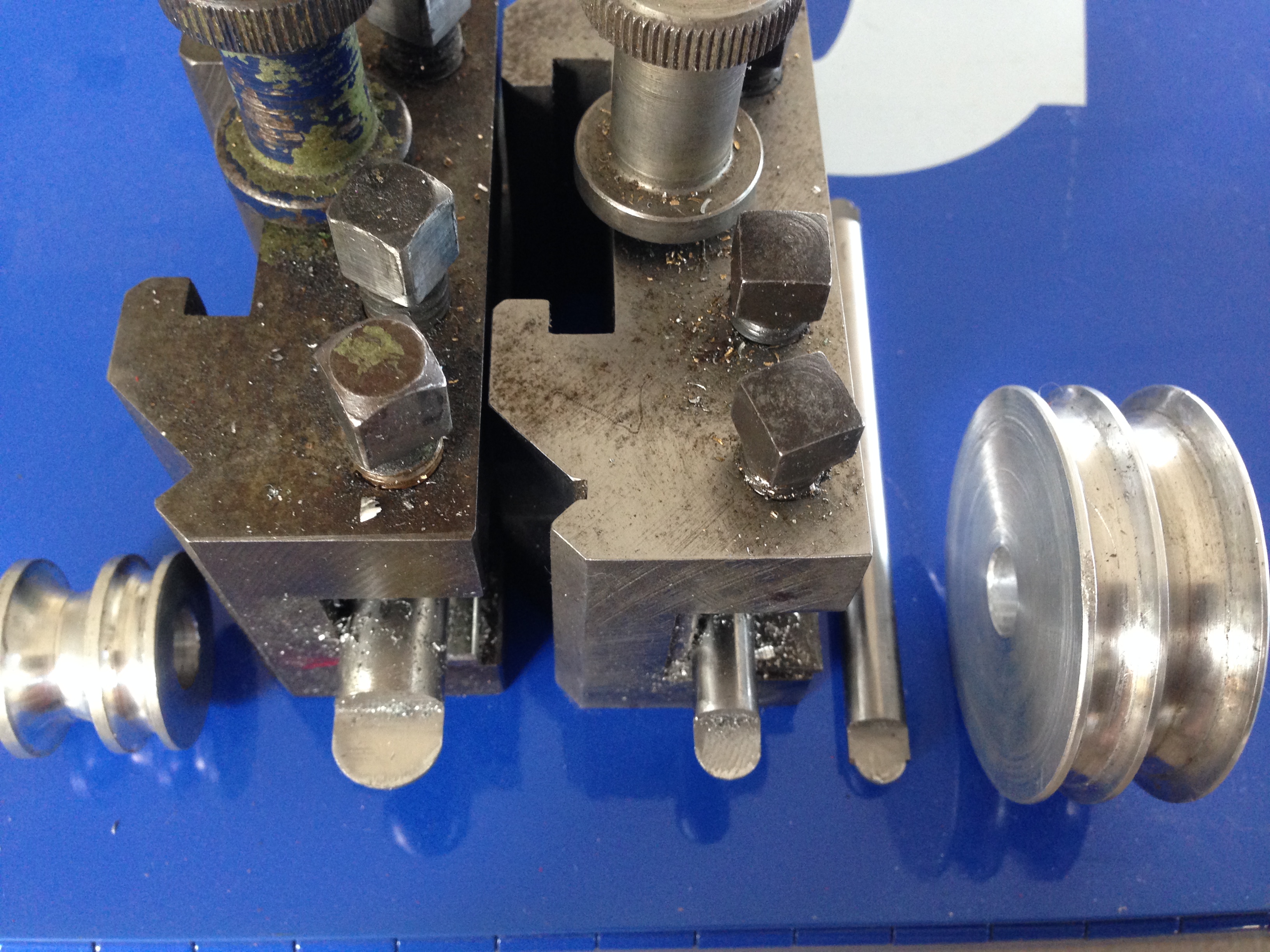
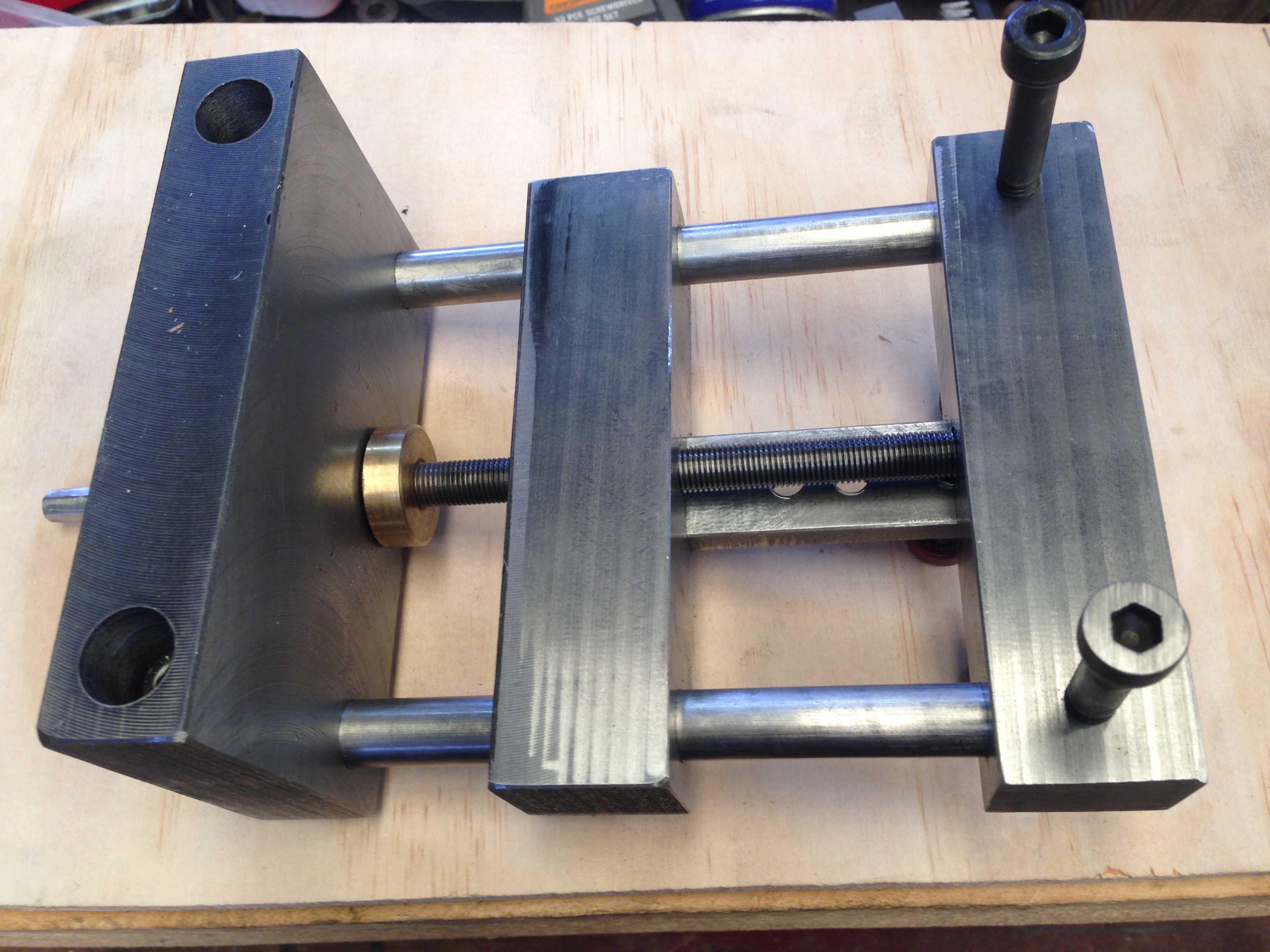
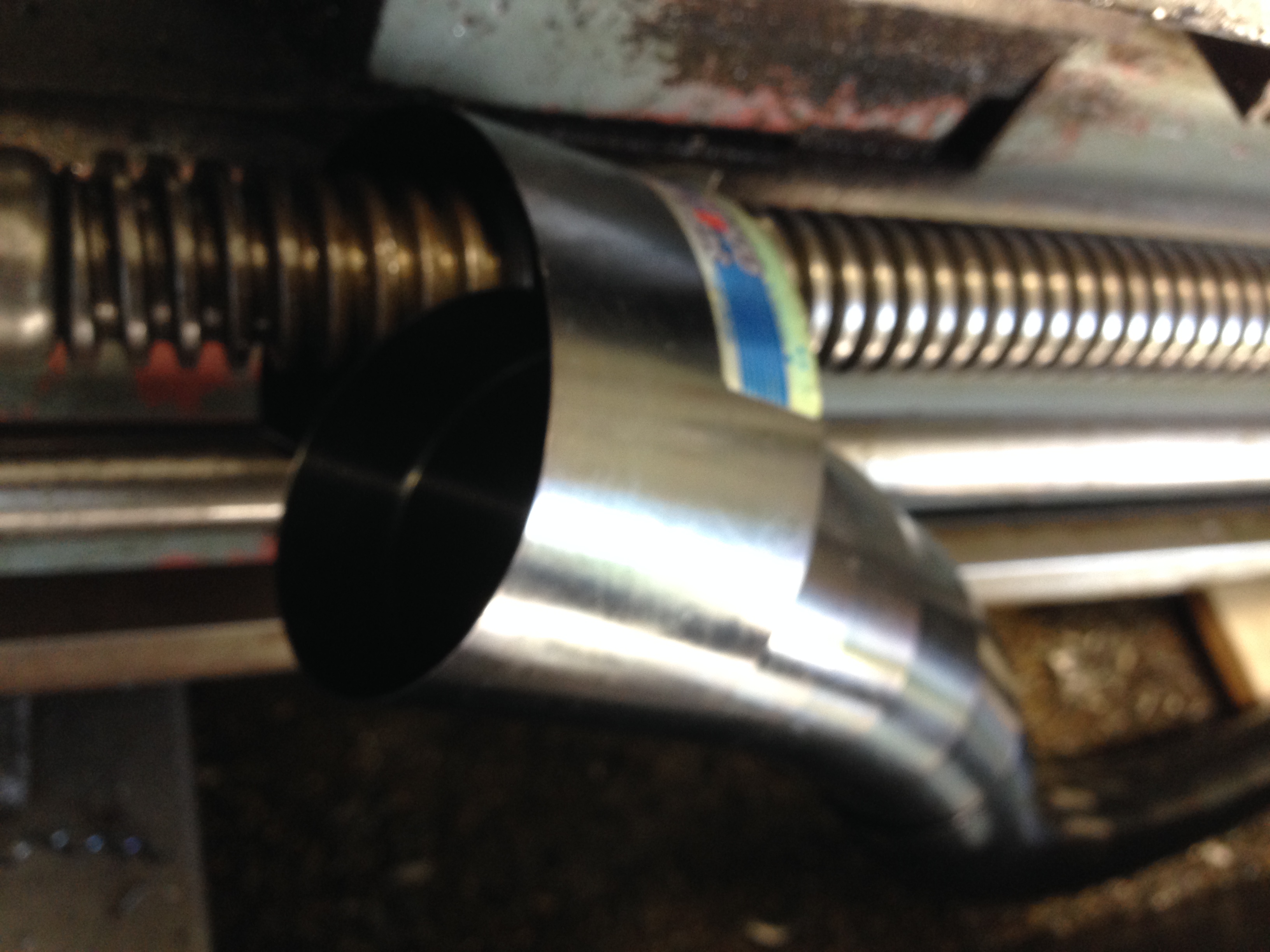
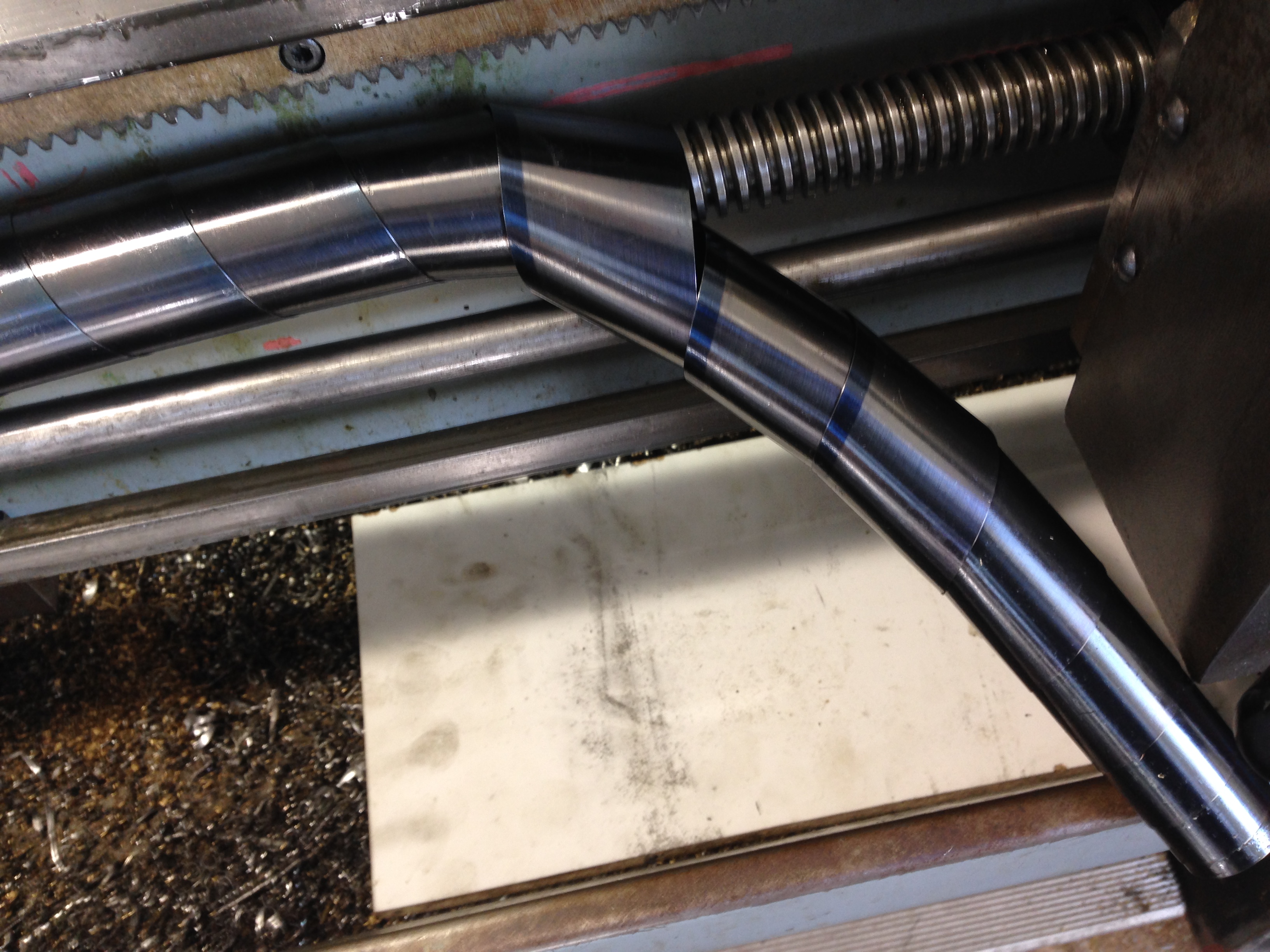
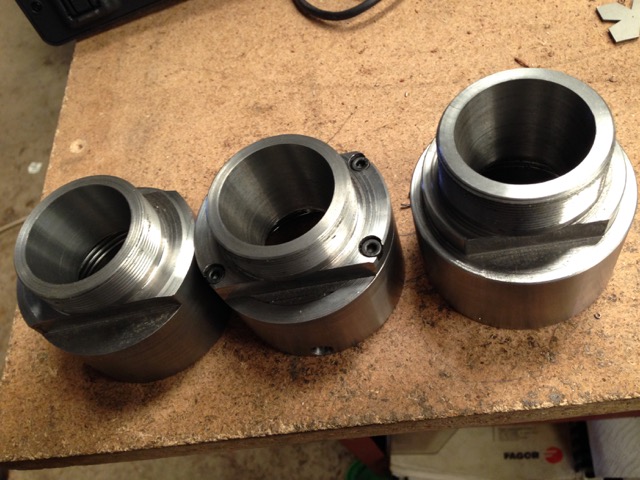
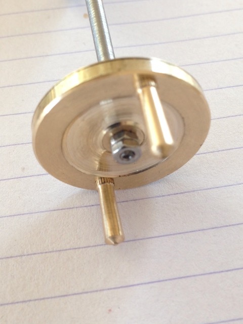
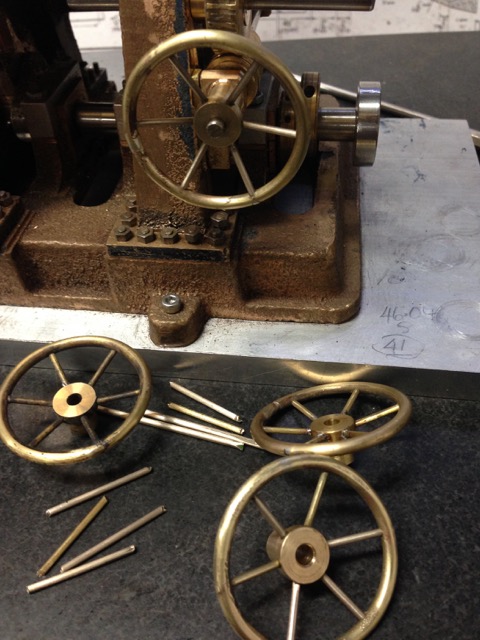
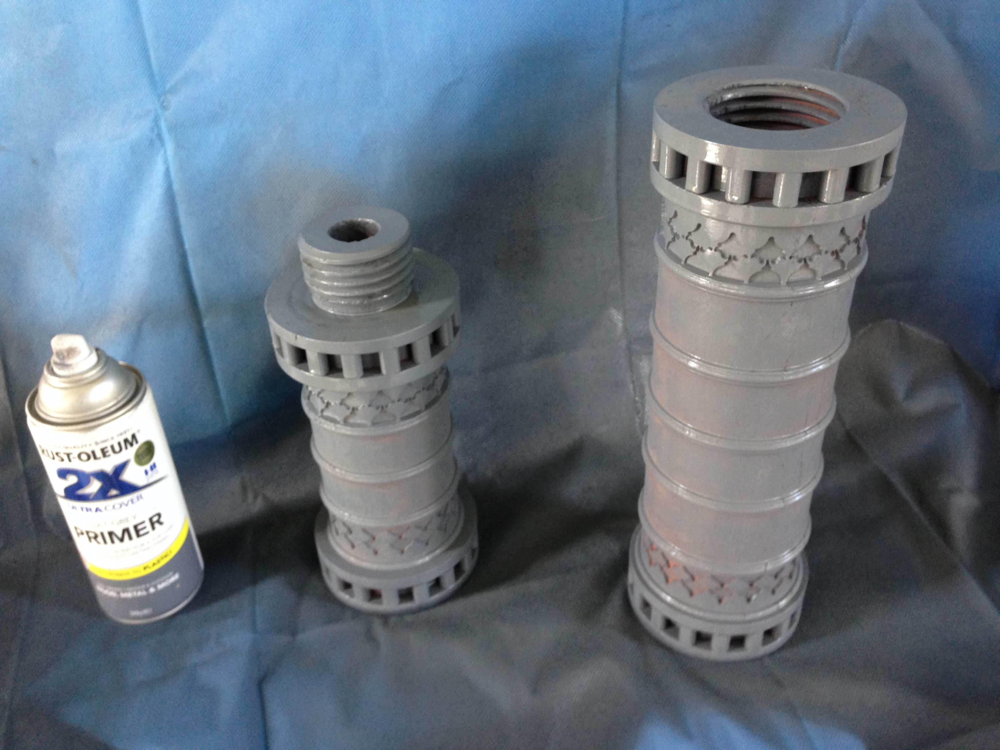
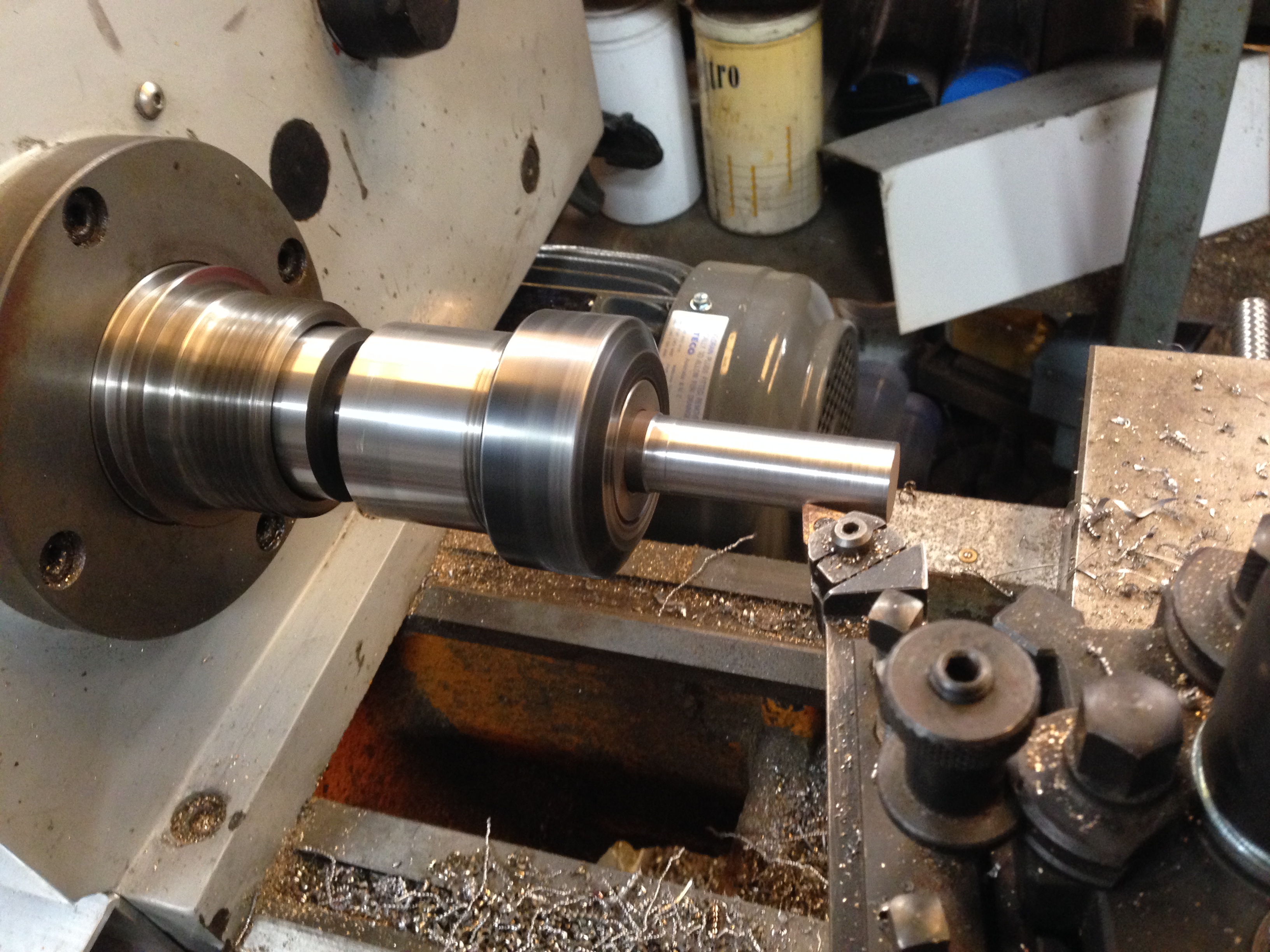
I decided to retain the hub of the gear and to add on a new ring which will be machined, and then new teeth cut into it.
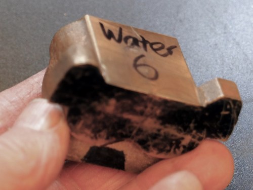
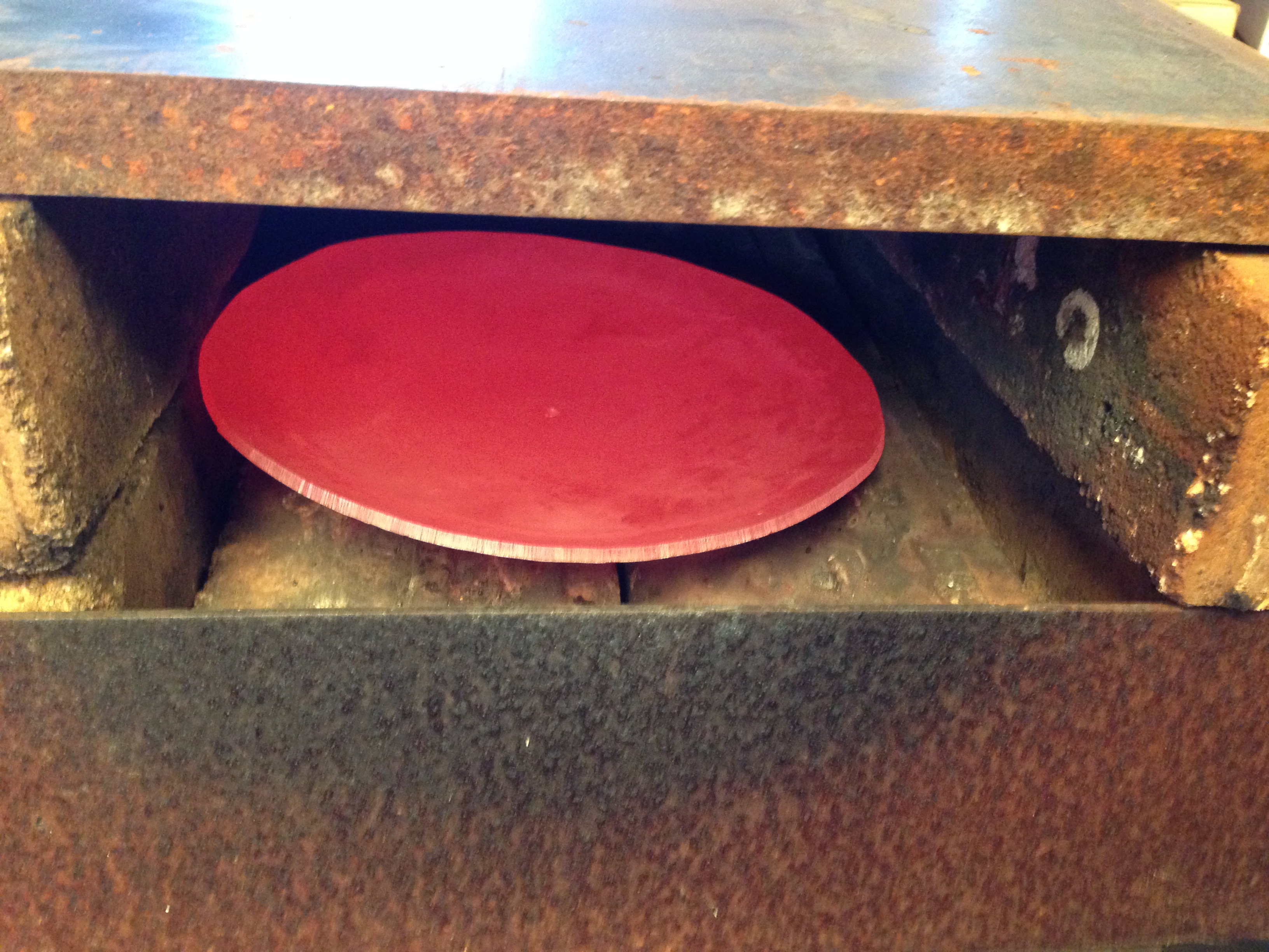
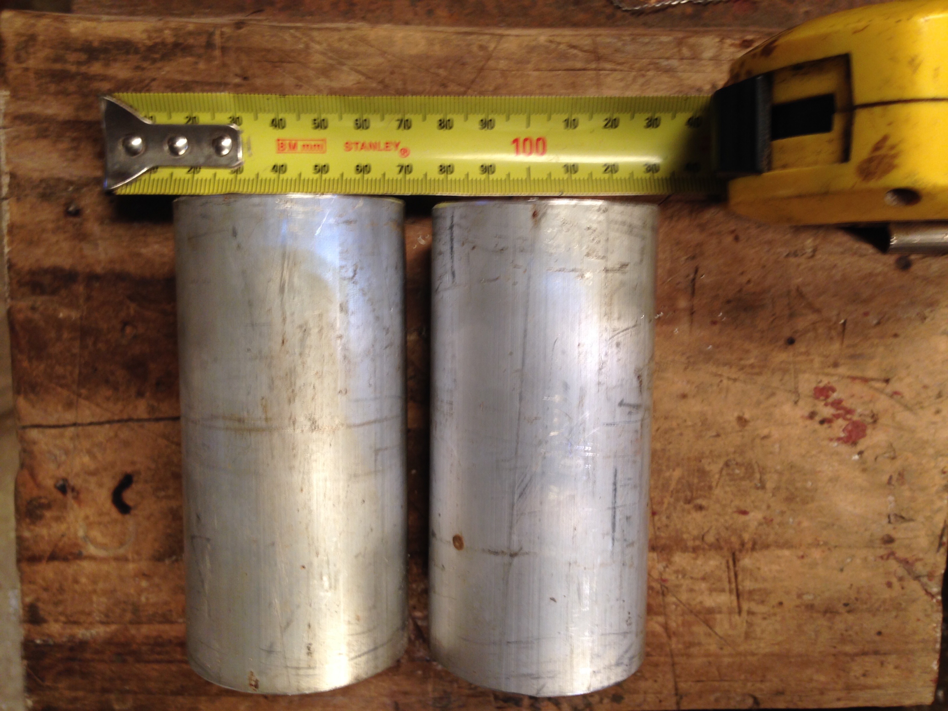
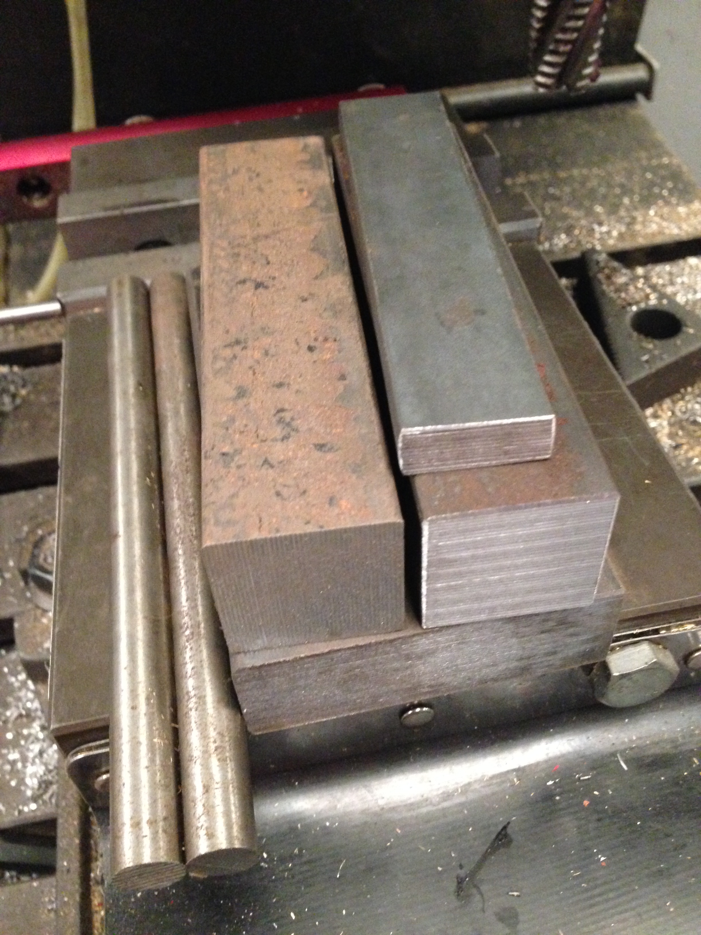
Firstly I had some 25mm steel plate water jetted approximately to size. I chose water jetting in preference to laser cutting or oxy-acetylene cutting to avoid any inadvertent heat hardening.
I also had the original gear water jetted to remove the outer 25mm, including the teeth, because it had originally been heat treated hardened, and I did not fancy machining that on my other lathe and maybe breaking more teeth!
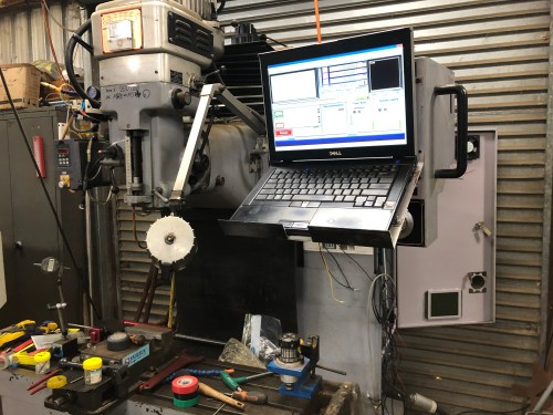
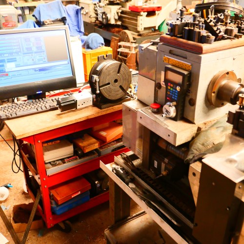
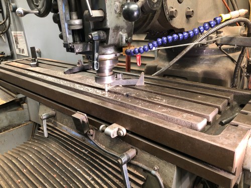
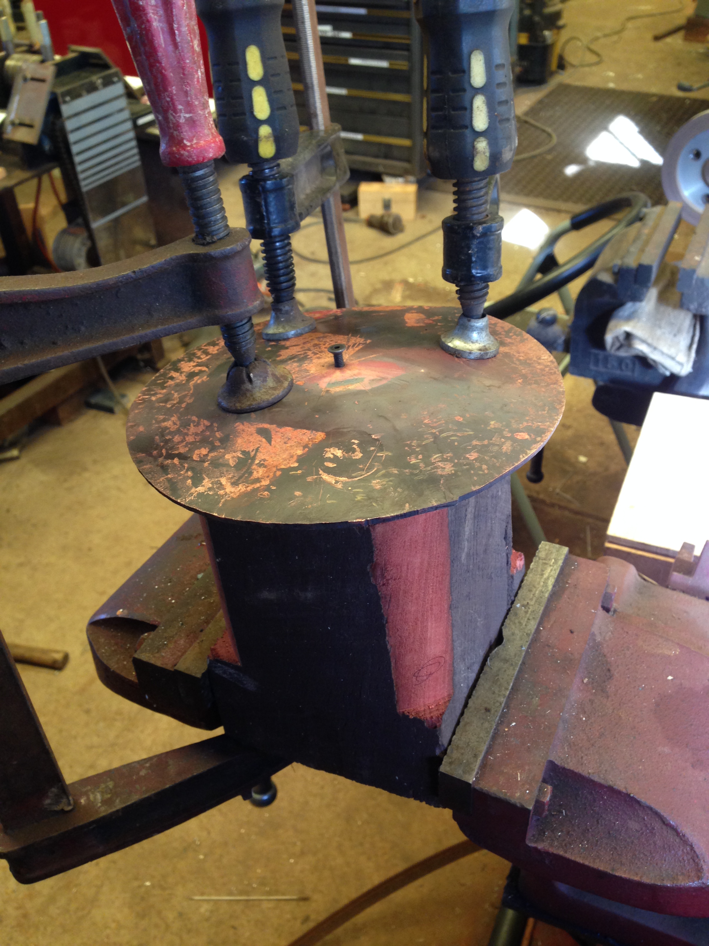
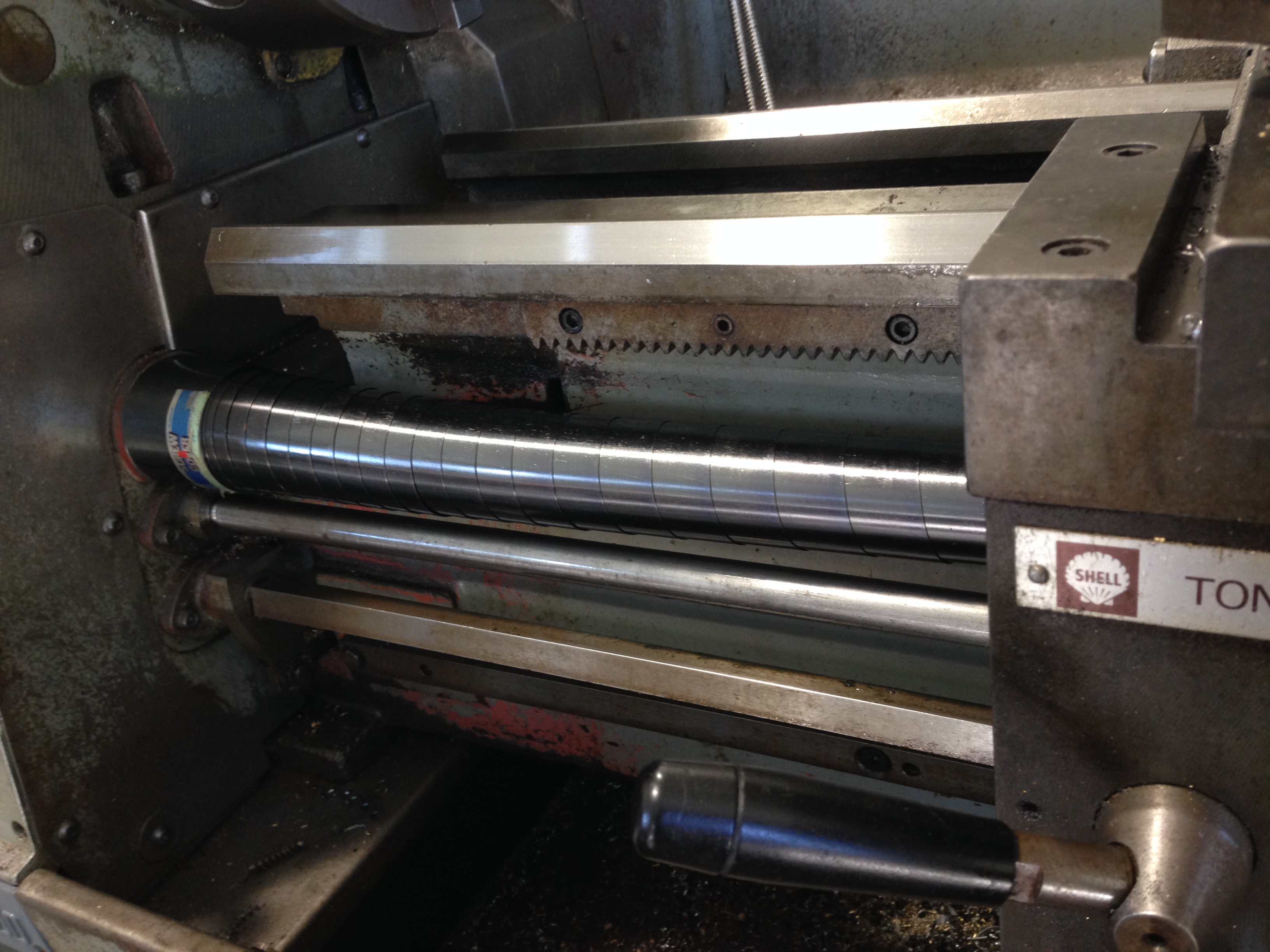
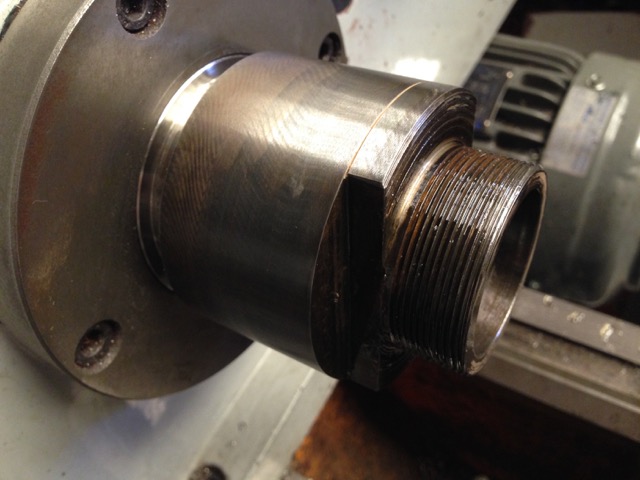
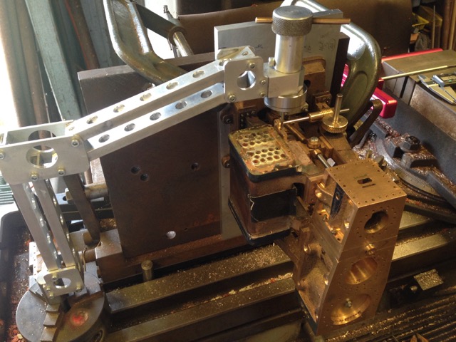
It was not cheap. But a nice finish, which machined easily. So the hub and the blank ring were machined with a 0.1mm gap, and glued together with Loctite 620. Then Scotch pins were inserted. Since my CNC mill is out of action, I reverted to calculating X and Y co-ordinates, using FS Pro. See screen shot below.
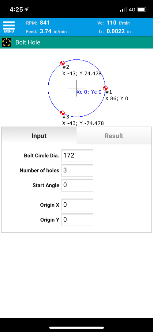
My CNC mill is out of action, so I reverted to doing some XY calculations on the manual mill with DRO, using FS Pro. Screen shot above.
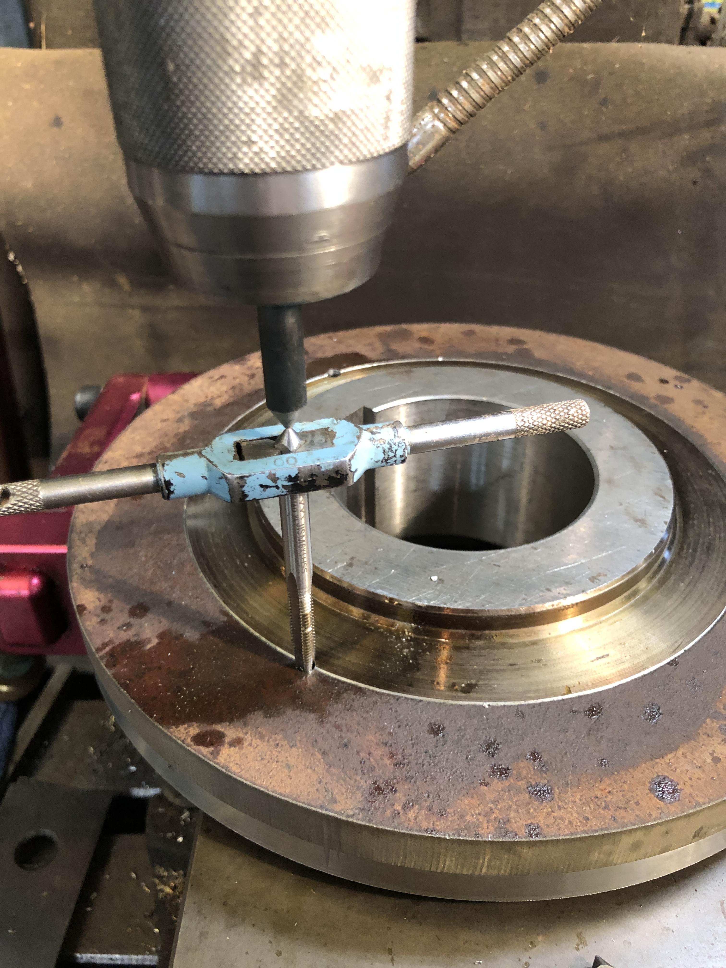
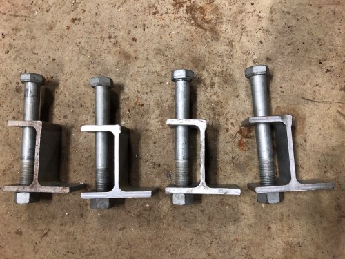
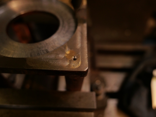
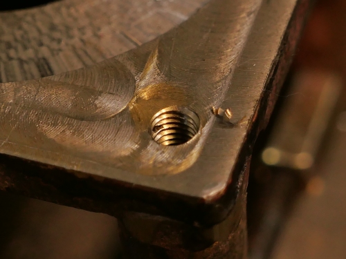
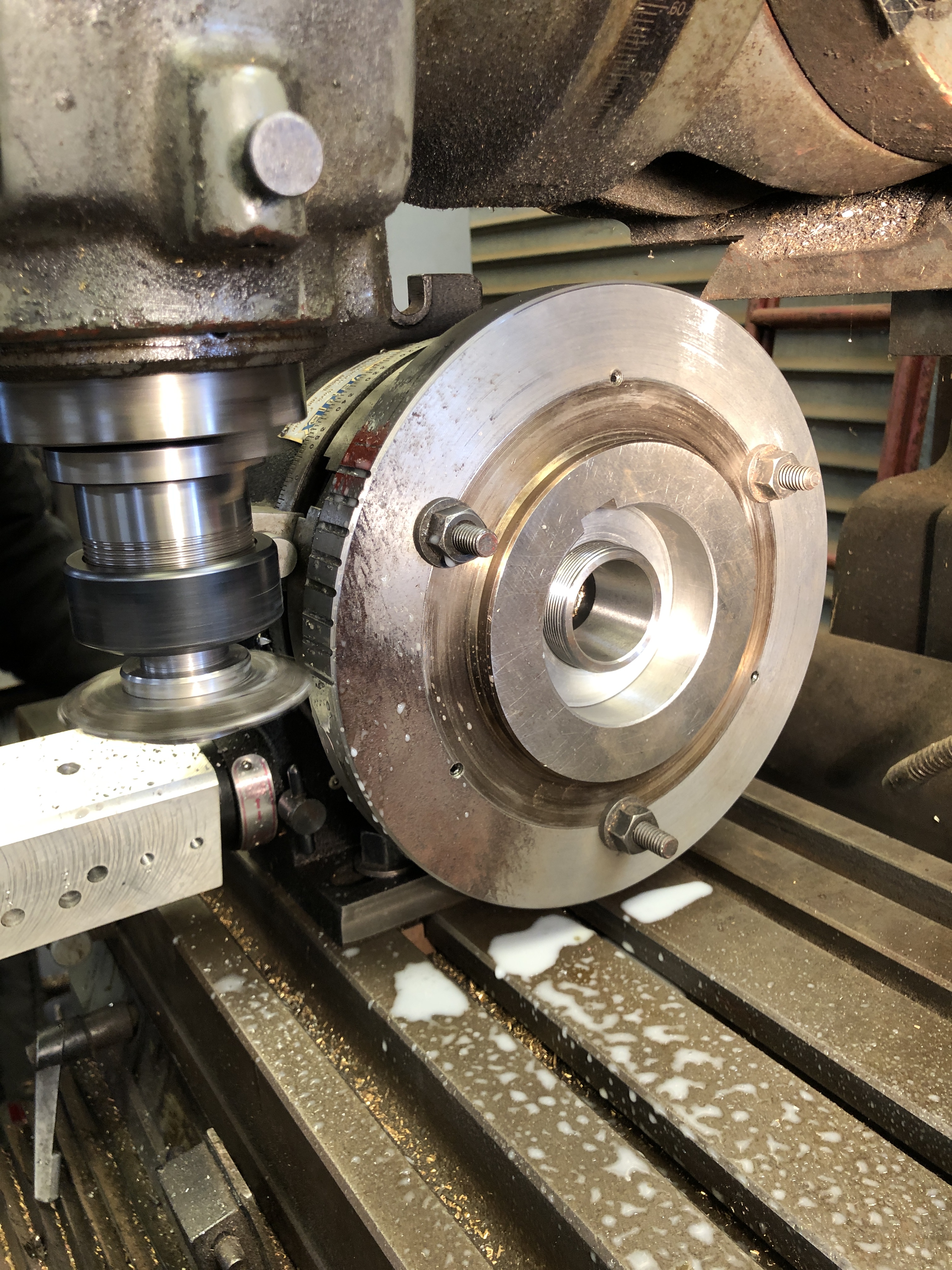
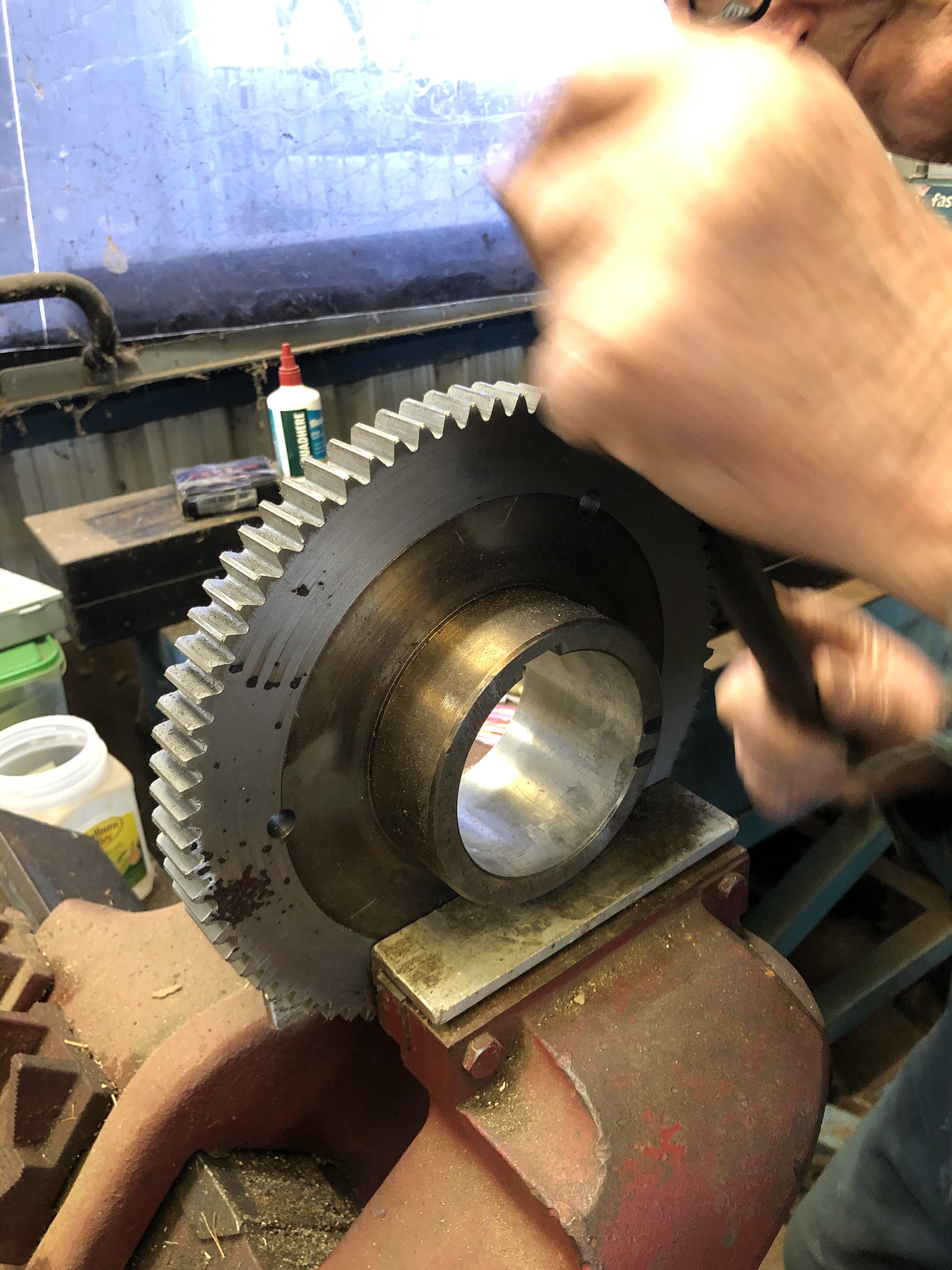
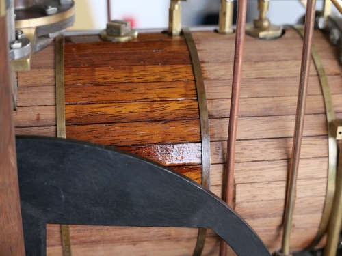
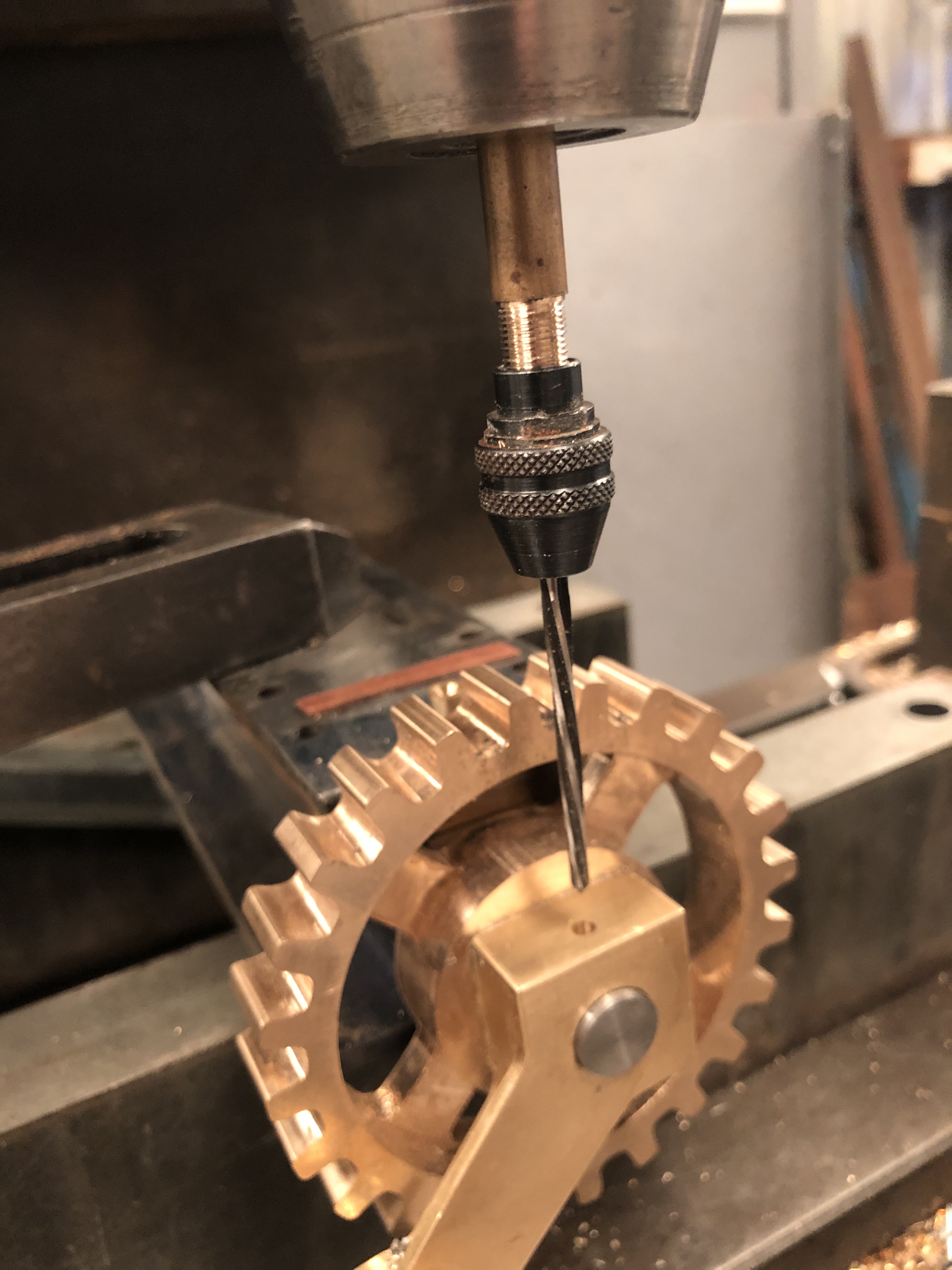
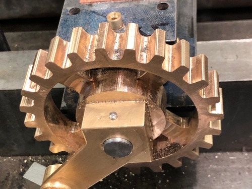
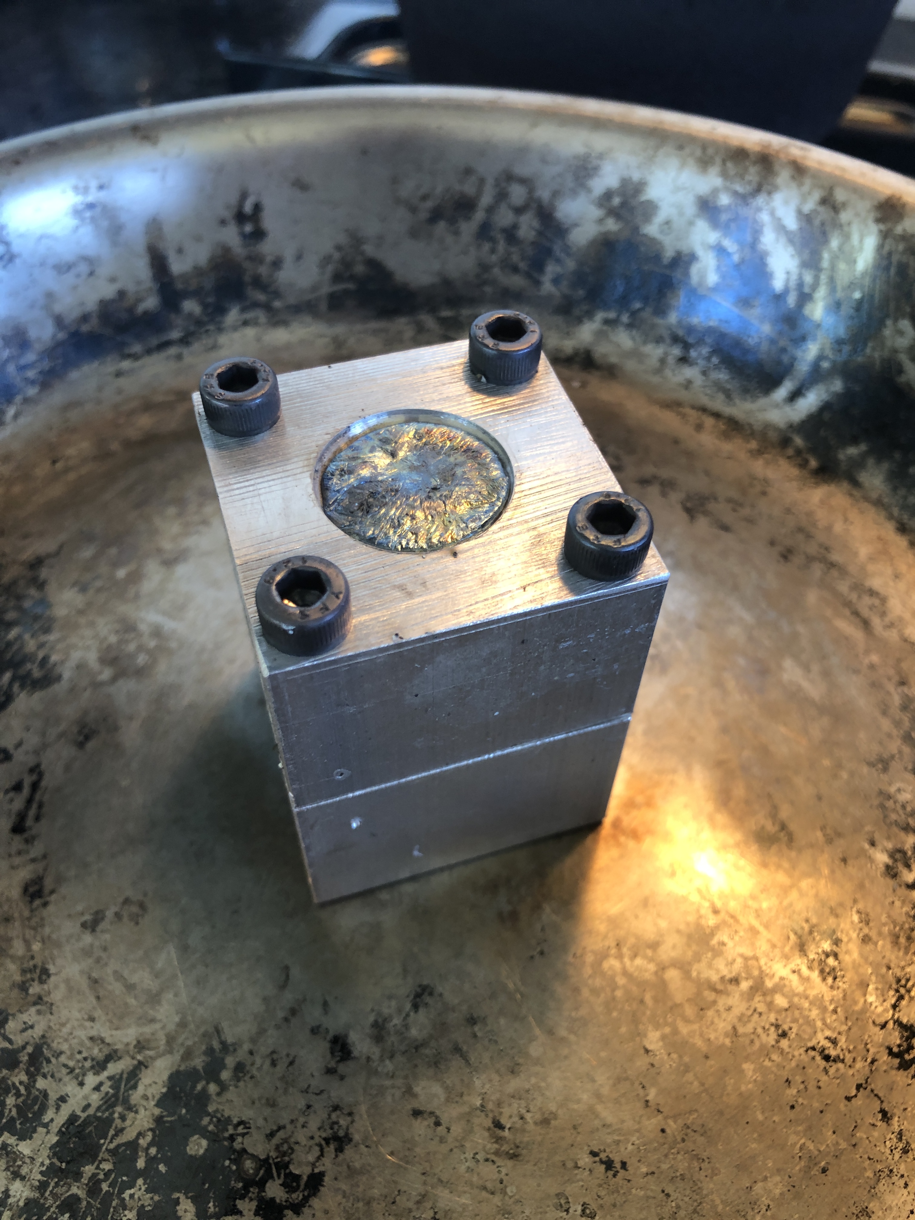
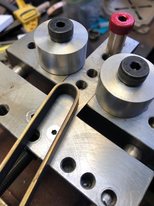
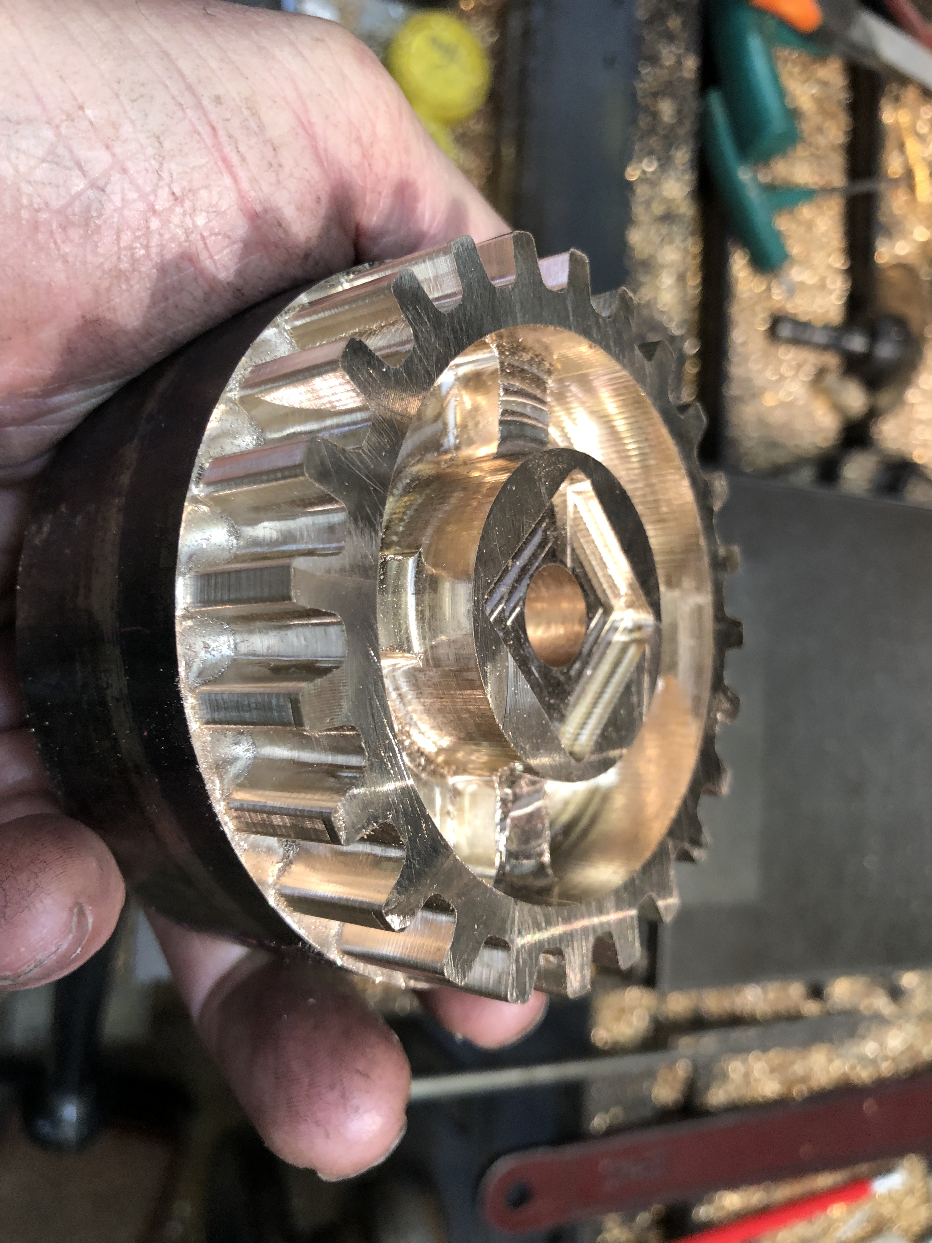
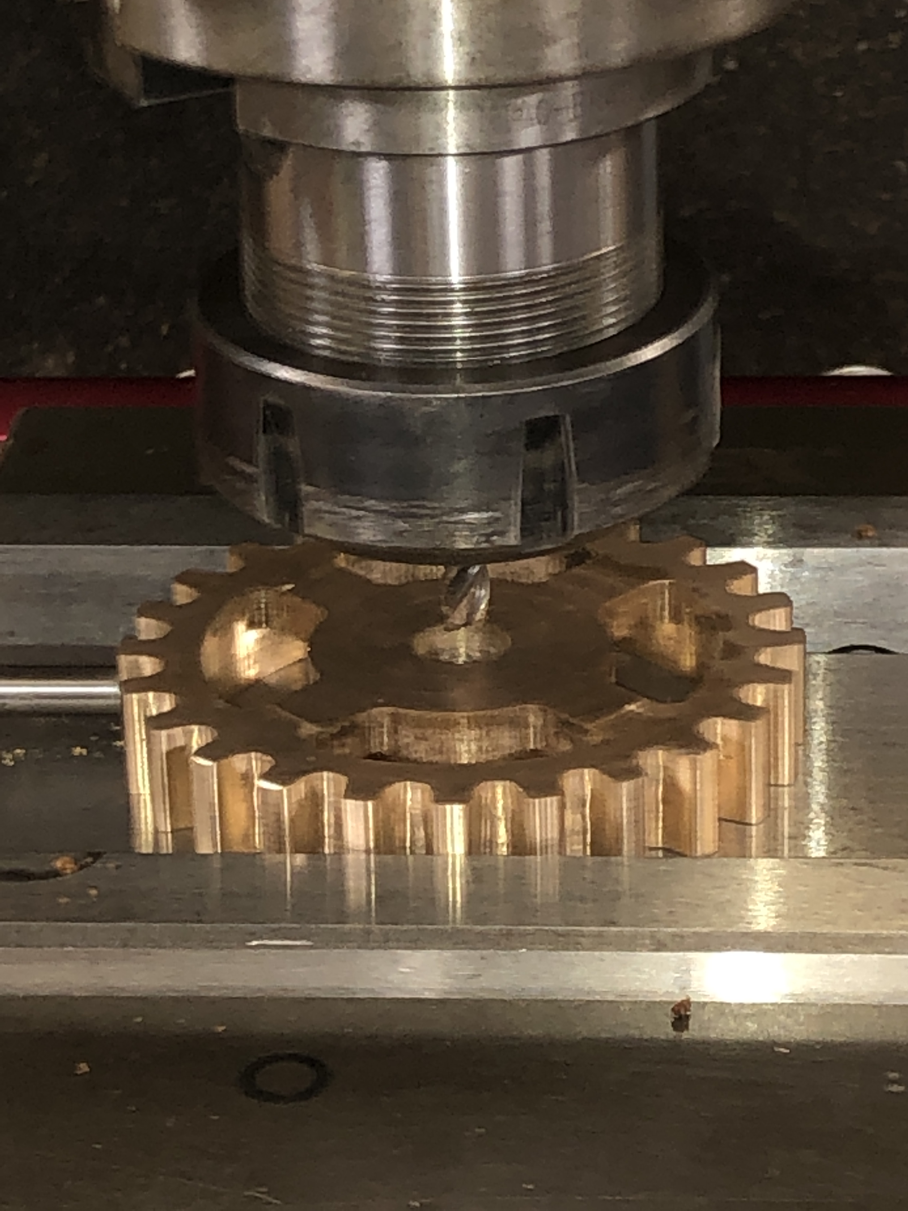
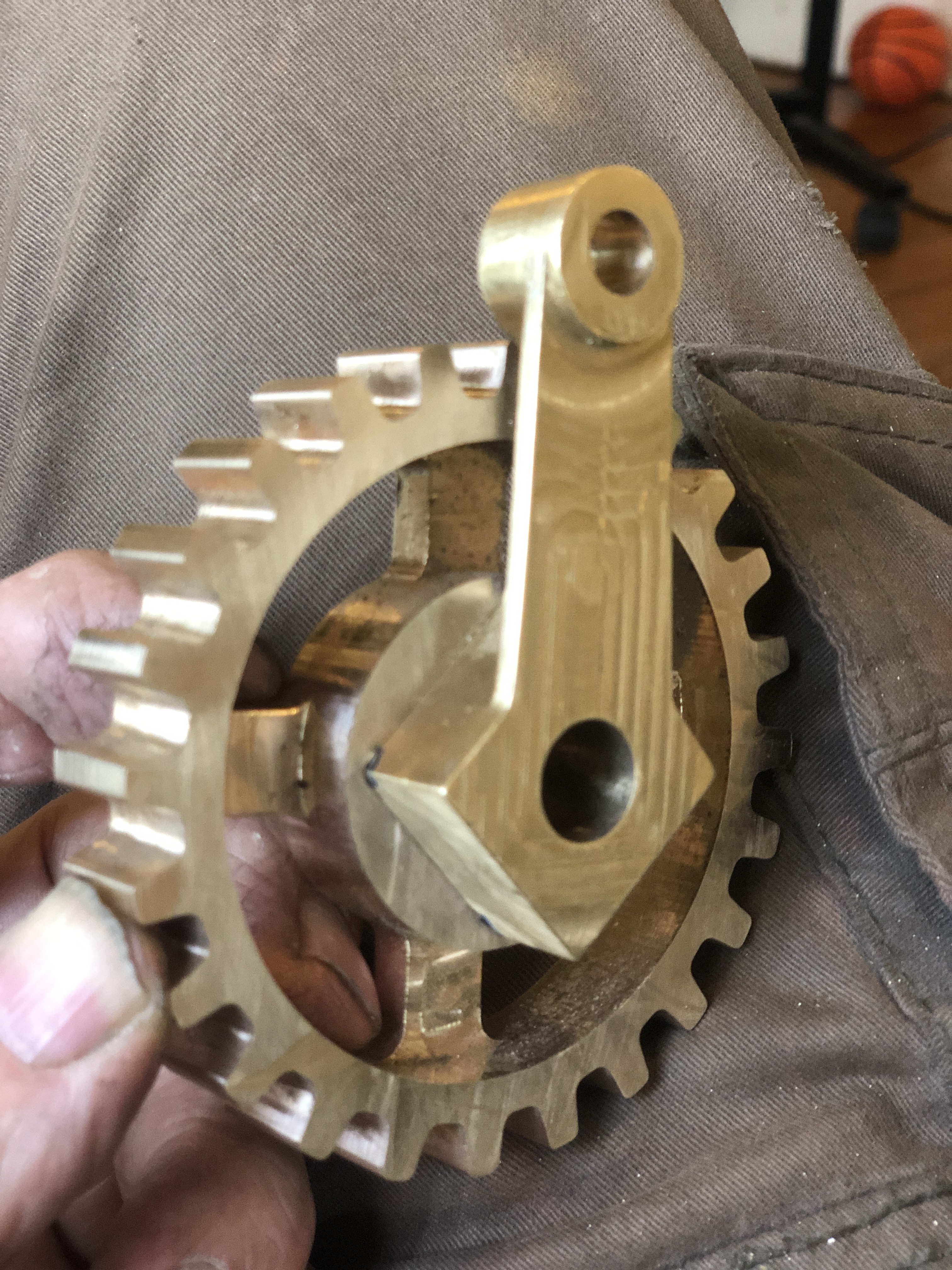
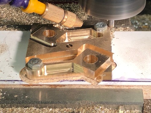
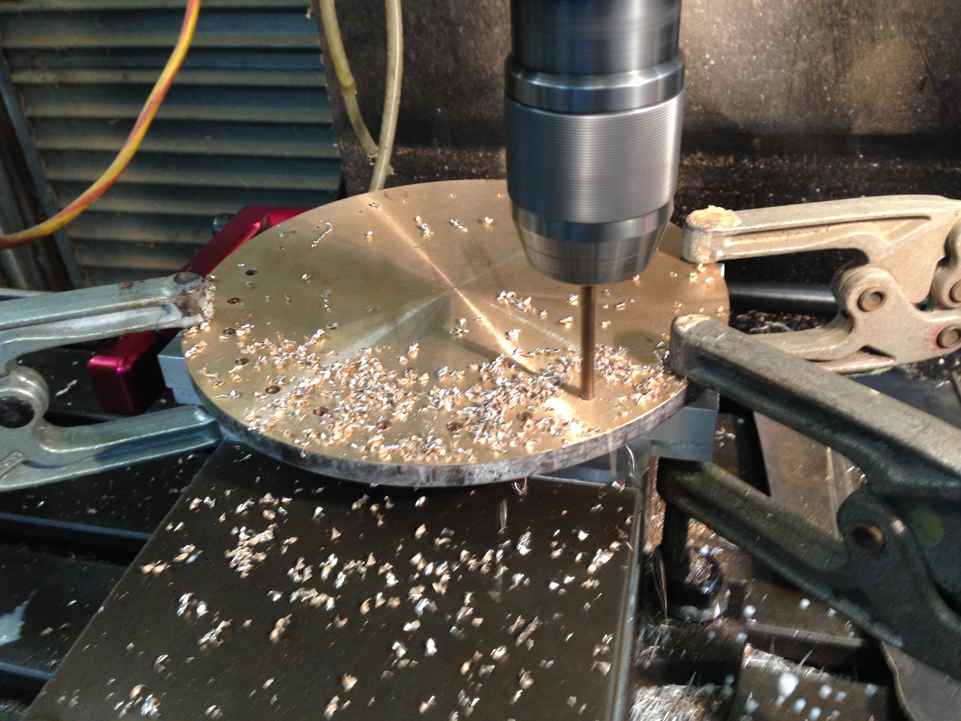
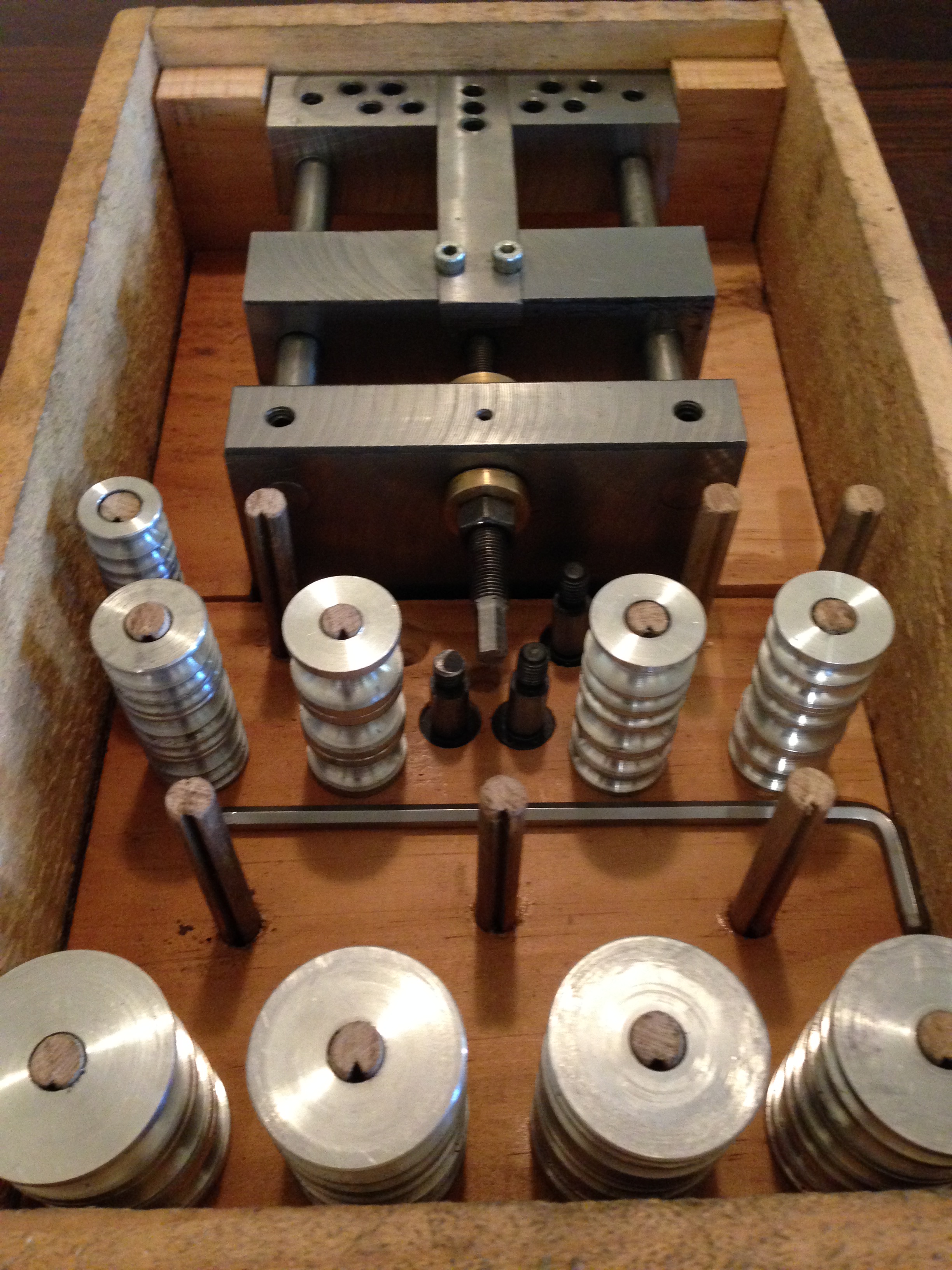
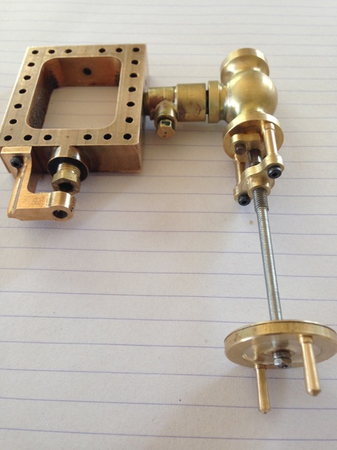
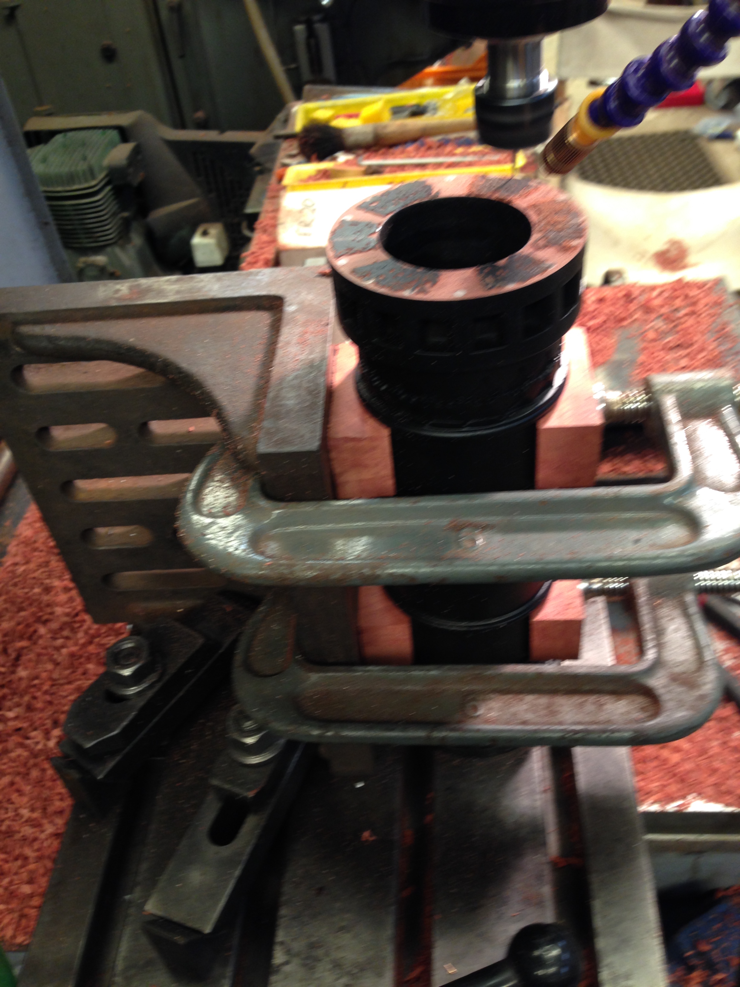
- And in the above shot, I have drilled and threaded some M6 holes and Loctited in some M6 grub screws.
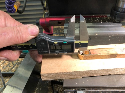
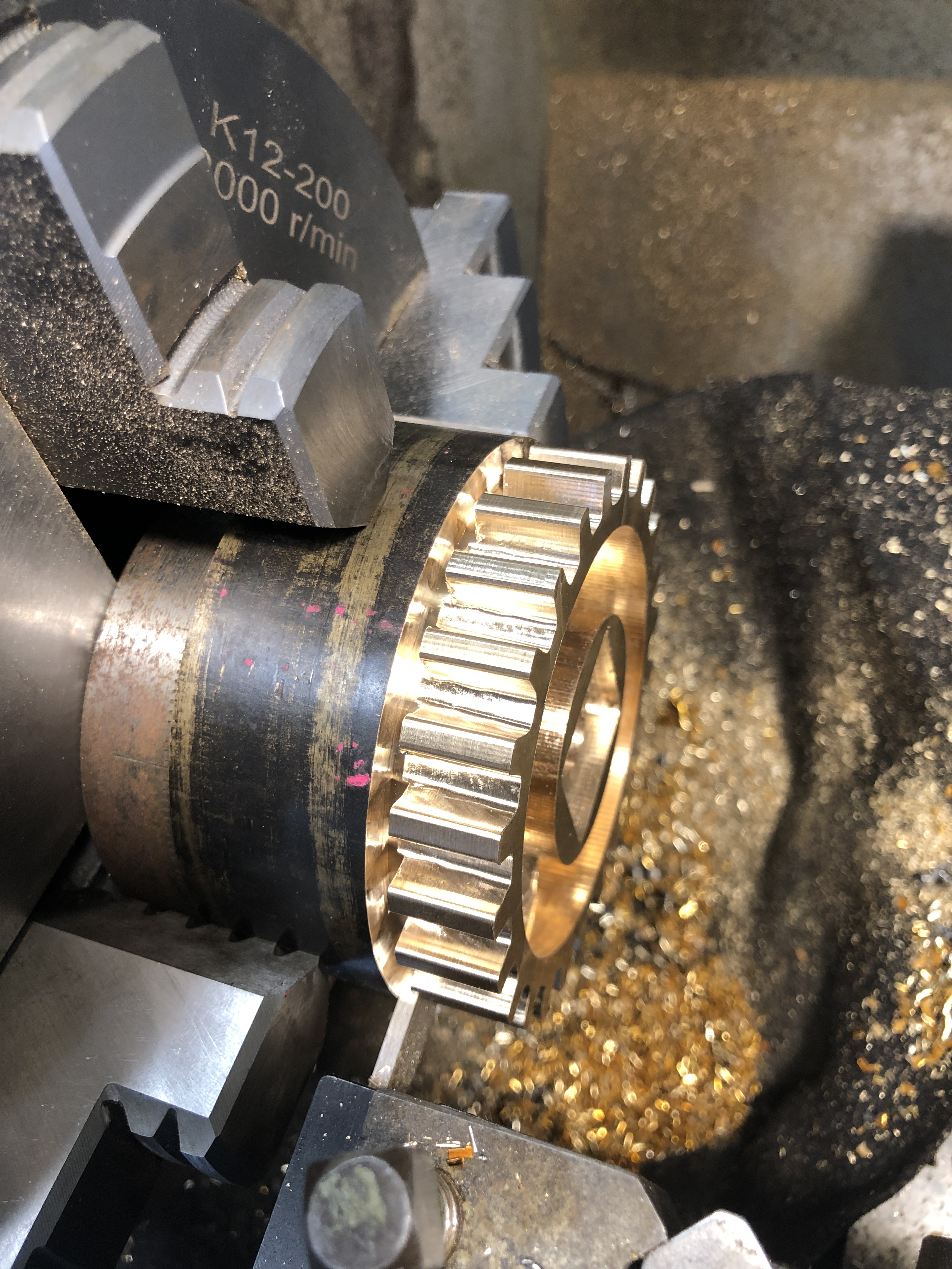
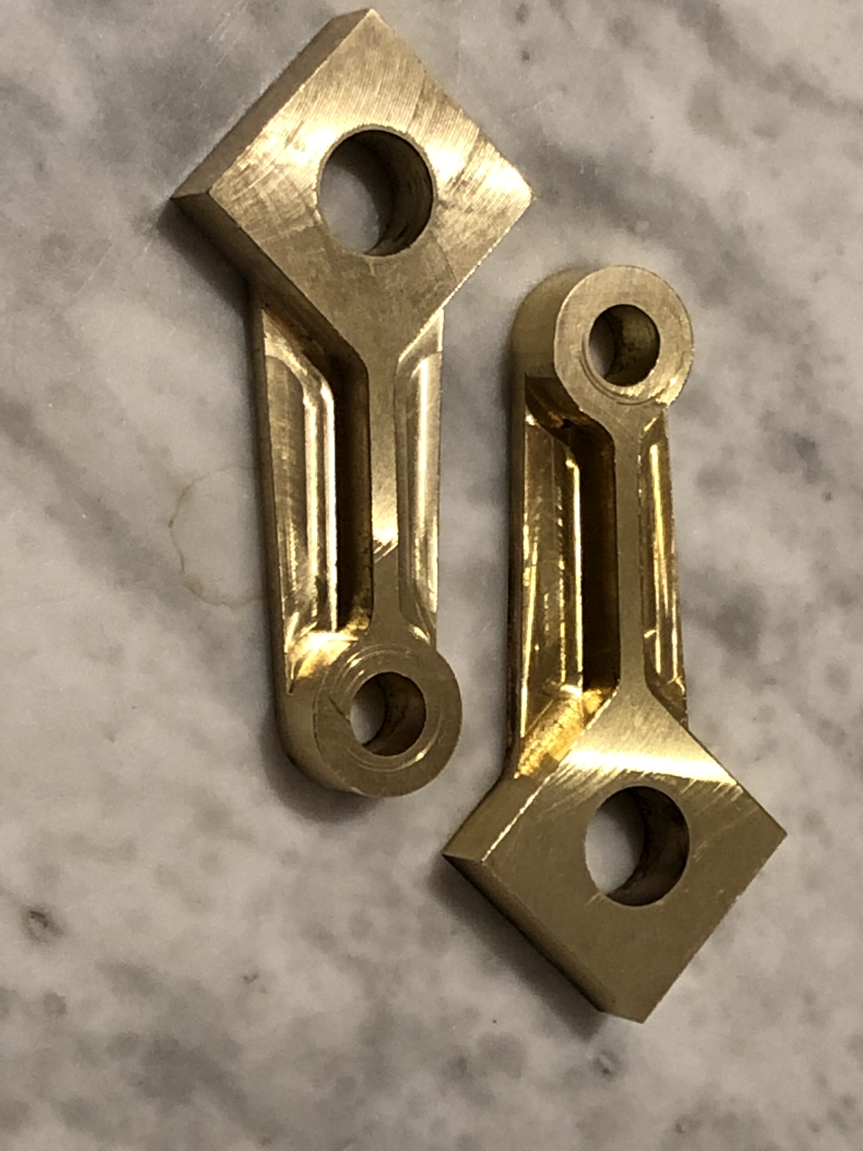
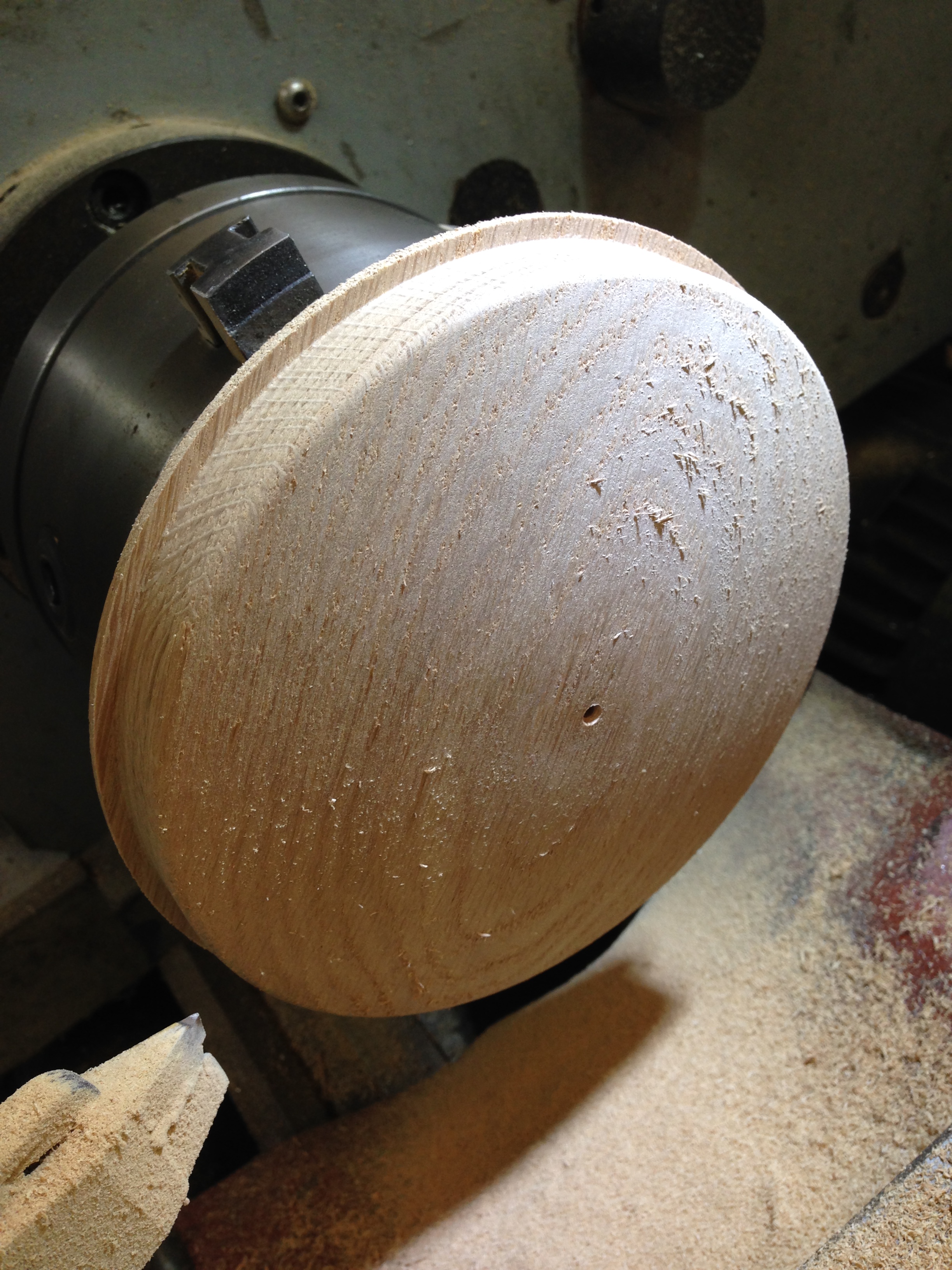
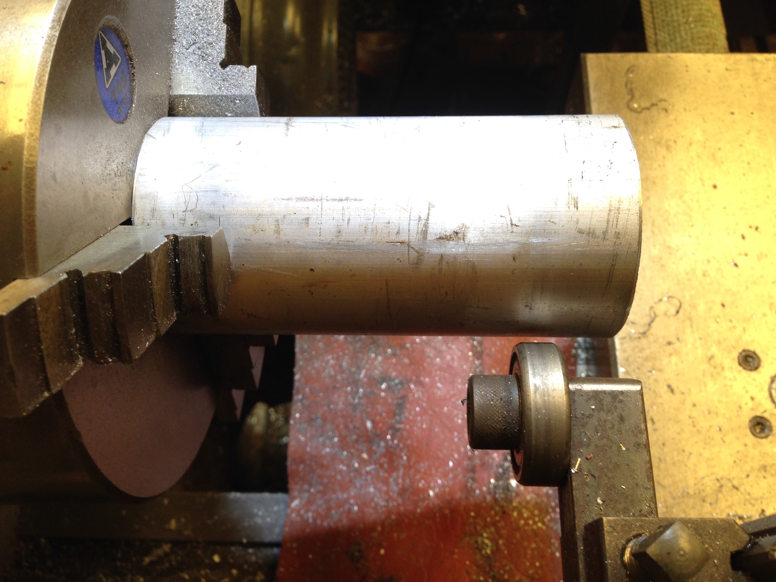
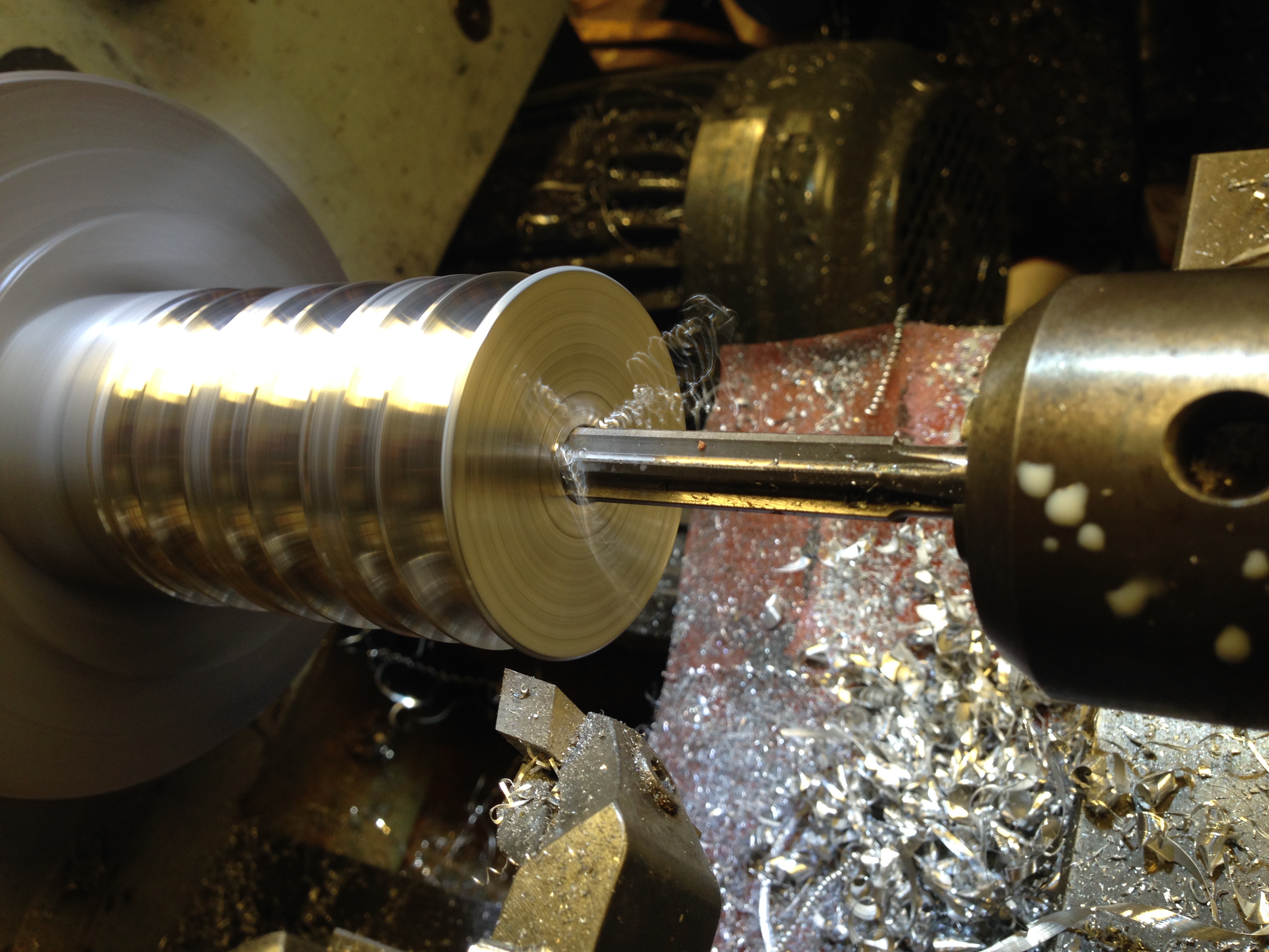
Then machined it to size,
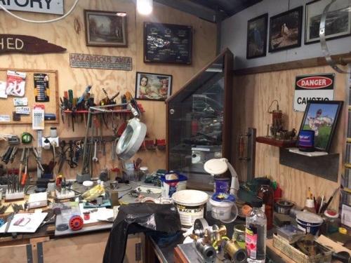
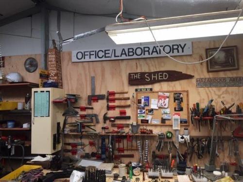
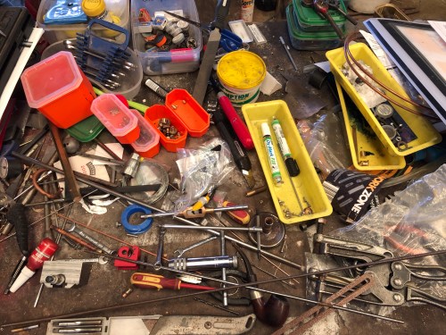
So, this post might be a bit ramshackle and disorganised. A bit like my workshop at present, and possibly my brain. My GP has started me on blood pressure medication, so I will blame that.
Watch this space for cutting the gear, soon.