johnsmachines

machines which I have made, am making, or intend to make, and some other stuff. If you find this site interesting, please leave a comment. I read every comment and respond to most. n.b. There is a list of my first 800 posts in my post of 17 June 2021, titled "800 Posts"

USS CONSTITUTION MODEL – 2

2. THE HULL. Early Steps.

The model will be 973mm long, 667mm high.

Construction starts with the hull, specifically the keel. The model keel comes in 3 pieces of 4mm plywood which are glued together. The instructions specify that the slots for the bulkheads should be positioned on top of the plans. Since the provided cut pieces are not absolutely accurate, some trimming with a sharp knife was required. I used to own some scalpels, and boxes of spare blades, but unable to locate them so I purchased an “Exacto” knife and a packet of spare No 11 (pointy, straight blade) blades. To avoid getting glue on the laminated plan I covered the plan with GladWrap.

The 3 numbered pieces of pre-cut plywood, trimmed by me to size, ready for glue. I used PVA white glue which did not adhere to the GladWrap. The keel will not be visible in the finished model, but it is the backbone of the ship, so needs to be strongly joined.
The instructions say that the pieces should be nailed to the baseboard, but I decided that was not necessary, and just weighed them down with a board and books, and left the glue to cure overnight.
The instructions suggest gluing some strips of paper over the joins, and since the glued keel was a bit bendy laterally I complied, and to my surprise the paper reinforcement did indeed stiffen the keel considerably. Live and learn. The strips holding the keel vertically were stapled to the baseboard. I numbered the slots to match the bulkheads. The original Constitution did not have bulkheads like the model, of course, just heavy frames and about 4 times as many. But the bulkheads will not be visible in the model, so I proceeded to use them. If I do one day make another wooden ship model, I will use frames, not bulkheads.

The next step specified gluing the bulkheads to the keel, but reading ahead I noted that the top deck was in 2 layers, and held to the bulkheads in neatly fitting slots. Also, the depth of the slots in both the keel and the bulkheads was quite variable and not in a straight line. And the bulkheads needed to be at 90 degrees to the keel, and vertical to the baseboard. And the plans were not dimensioned.

So I used a different order of assembly. I do hope that this variation does not return to bite me on the bum. I glued the 3 deck panels together, after doing a dry run assembly of the keel, bulkheads and deck pieces, and reinforced the joins with paper strips….

The deck panels glued together, again after measuring and trimming, making sure that the overall shape was symmetrical, and fitted the keel with bulkheads not glued yet. Then glued on paper. Some penetrations were covered with the paper strips, and cut out after the glue dried.
Then made sure that the glued up deck panel fitted the bulkheads. Some enlargement of the undersized deck panel slots was required, but it is starting to take shape, No? The deck panel will not be visible after it is covered with planks later.

So that is where we are up to, after 2 days of about 6 hours/day. So far it has been very enjoyable.

Broken Crankshaft

The lovely 1:4 scale Fowler traction engine which I bought in 2017 has had little use in the past 3 years, so I have decided to sell it. The lack of use was mainly due to Covid shut down of steam meets and exhibitions. While Covid restrictions have ceased, my interests have changed, and I now prefer to concentrate on smaller, stationary steam engines.

But first I needed to renew the boiler certification. The boiler is constructed from 4mm thick copper, silver soldered, and was made by an experienced engineer, so I do not expect any significant problems with the re-certification. Just to be sure, I ran the engine on compressed air. Immediately I noticed that the flywheel was rotating more slowly than the crankshaft. The cause was a sheared pin which joins two segments of the crankshaft.

The flywheel has always had a slight wobble, but now it was more pronounced. Obviously the crankshaft needed to be repaired or replaced. Initially I hoped that all that would be required was a new pin. It was a 1/8″ roll pin, and I hoped that I could tap it out and simply replace it.

I have the original construction plans for the engine, and those plans recommend a solid crankshaft in the interests of longevity. However, the original maker had chosen to make a built up crankshaft, securing the 8 joins with roll pins, and probably Loctite.

I contacted the original maker of the engine, an elderly gentleman living interstate, and we had a long and pleasant conversation. He was surprised that the crankshaft had failed, but did not recall the details of the construction. He strongly recommended removing the crankshaft from the engine and working on it in the workshop, a decision which I had already made.

Long story shortened. It took me 4 hours to remove the crankshaft, and on the workbench about 10 minutes to punch out the broken pin, and separate the crankshaft parts.

Crankshaft, big ends, eccentric rods, main bearings and flywheel removed.
The crankshaft with undisturbed eccentrics, set up on 2 V blocks on a granite surface plate. With the 2 parts pushed together. But something was wrong. With the broken end clamped in the V block, the other end was held about a millimeter above the V block. WTF!

By this time the join had been cleaned with acetone, primed with Loctite 7471, and glued with Loctite Wicking 290. And reamed the hole to accept a number 1 taper pin.

So I checked the diameters of the mainshaft at both ends. 23.47mm at the broken end. 22.86 at the high end!!! Bugger. I should have checked before gluing. But why would the mainshaft have different end diameters???

Oh well! I decided, foolishly with hindsight, to reassemble the whole engine and see if the discrepancy was noticeable.

Next day, another 4 hours, and the reassembly was complete.

Rotated the flywheel. And it was horrible!! The flywheel runout was not “noticeable”. It was horrible!!

It had to be redone. Or do I just bite the bullet and make a new crankshaft?

I decided to redo the repair job, lining up the parts in the lathe.

Long story short again… teardown was much quicker this time. Experience counts.

This time I took a very light skim off the shaft and face using a very sharp cutter, to ensure that the ends and roughness were removed. Then held the broken shaft in a collet chuck which I know is very accurate. But found another problem. The shaft at the other end of the crankshaft had not only a smaller diameter, but was also at a slight angle axially, so I could not use the machined centre in the end of the shaft. So I set up the fixed lathe steady pictured, mounting it at the main bearing location. Trouble was that I had no accurate method of centering the steady. I described this setup to my engineering group, and was informed that I should have used a set up rod machined to the diameter of the end of the crankshaft, to set the position of the steady. Makes sense. My bad.

Oh well. I will reassemble the engine again. If it is again horrible, I will either do the whole job again, properly this time, OR MAKE A NEW CRANKSHAFT.

I have a feeling that I will be making a new crankshaft.

p.s. I allowed a day for the Loctite to cure, then deeply reamed the existing hole, and reinserted the taper pin in the enlarged tapered hole. This time the head was buried, but there should be enough purchase to remain intact.

Reassembled the engine, and turned it over to check the flywheel wobble.

I will not claim that it is perfect, but it is very close. I will not start making a new crankshaft just yet, but that is the next step if this repair is eventually unsatisfactory.

Boiler recertification next week.

THE LAST POST

8 years, ~900 posts. 13gB storage full. WordPress offers the solutions of buying a business package at 3 times the price, or deleting old posts to free up some space. I have removed almost all of my videos, with considerable reluctance, to make space to finish the posts about the Armstrong 110pr model cannon construction. However I still get comments from posts posted when I was a newbie, so I am not prepared to delete any more of them.

Just a thankyou to you, my reader. Questions, comments and communications from you are the grist for the mill of blog posters, and I am no exception. I have really enjoyed the journey. Feeling a bit sad, but I will resume my private diary entries, instead of venting my thoughts on johnsmachines.com

I had said that I would move johnsmachines.com to another platform, but now I am not so sure. Some repairs to my house are my next priority, and that will be too boring to blog. At this time I am not moved to start another model, but down the track, who knows?

I had saved the last little bit of storage space for the final photos of the Armstrong 110pr model cannon. Photos of the finished model follow.

The wooden carriage and traversing platform were stained with Japan black, then several coats of spray lacquer. It will be rubbed with steel wool and wood oil to give it a silky smooth finish.
Focussing on the rear tangent sights. I might add some locking screws to the sight posts later, but then again, I might not.
About 10º of elevation, provided by removing the quoin, and resting the barrel on the Smith’s elevating screw via the bed. Note the iron binders on the ends of the wooden slides.
Top view. Queen Victoria’s cypher, the barrel weight (just over 4 tons), and the proving arrow. No touch hole on the model. This view also shows the asymmetric position of the sights, caused by canting the rear sights ~2º, and moving them 2mm to the left so they are equidistant from the bore at the nearest point.
Almost horizontal with the Smith’s screw and quoin elevating the barrel. I will add some ropes and pulleys later. The right gunners’ platform needs to be pushed down a bit to sit in its correct position.
From the front. The wheels only contact the slides when the rear is slightly levered up, to encourage moving the carriage from the recoil position back to the firing position. (not that this model can be fired. It has no touch hole). Also note the absence of trunnion caps, which was common in garrison guns.
The model foresights were deliberately blunted to avoid observer injury; and left trunnion markings. EOC for Elswick Ordnance Company, barrel number 212, and 1862 the year the barrel was manufactured. Copied from an original Armstrong 110pr.

And that, dear reader, is that. Goodbye, best wishes, and thank you.

Model Armstrong 110pr Sights

The 1861 Armstrong rifled breech loader cannon had foresights on the trunnion ring, and rear sights on the breech. The foresights had fixed lengths. The rear sights were adjustable and graduated for range. The foresights were vertical. The rear sights were canted at a 2º16″ angle to compensate for slight lateral deflection of the projectile caused by the rifling. The rear sights also had a lateral adjustment screw to compensate for movement of the target.

At 1:10 scale, the components of the sights were tiny, and I decided to not make the lateral compensating adjuster. But I did decide to incorporate the 2º angulation. That required the left and right rear sights to NOT be equidistant from the centre line of the barrel. The drilling of the barrel holes for the sight holders was consequently not straightforward, and I spent a couple of hours on the CAD drawing to work out the drilling positions, depths, angles etc. And then considerable time was spent setting up the barrel in the milling machine vise, so that the bore was horizontal, parallel with the mill table, and level when the foresights were drilled, and tilted 2º when the rear sights were drilled.

That took two full machining sessions over two days. I was not looking forward to it, knowing that a broken drill or other mishap would be catastrophic. In the event, it all worked out OK. Some pics…

1. The 2º canting of the rear sights was established with 8mm and 10mm thick parallels sitting on 1-2-3 blocks under the trunnions. There is an 18mm rod in the bore, sitting on the jack to hold the barrel horizontal. A 4mm end mill is creating a flat surface from which to start the drilling.

2. That is a 2mm drill bit, silver soldered to some pipe to give it some extra length. “Tension drilling” again.

3. Checking the lengths of the foresights.

4. The almost finished sights. Left rear holder needs to be shortened. And yes, the magnified photo does reveal a previously undetected superficial crack in the left weighted arm. Luckily I have a spare part if it breaks. I must have used too much force when I pressed in the driving pins.

This series of posts is almost complete. Making the 1:10 scale model Armstrong Breech Loading, Rifled cannon, 110pr* took almost a year, and these posts were originally published by johnsmachines.com in wordpress.com. Since I am intending to cancel my subscription to WordPress I have decided to transfer some of the 900 posts to this new, for me, site.

Further old posts will gradually be transferred. And some new ones will be appearing.

Trunnion Rings Completed.

Today I turned the trunnions.

1. The centres were measured, marked and drilled. The squared end was held in a 4 jaw chuck and the end to be turned was held in the tailstock. Turned to 20mm dia with a “Diamond” tool holder and HSS 1/4″ cutter from Eccentric Engineering.

2. Then the turned end was held in an ER40 collet chuck to avoid marring the surface, and the tailstock end was turned.

3. One finished, one end to go.

4. Then I used the undersized laser cut parts to turn another “coil” (solid steel in the model, not a wound coil as in the full size cannon), also to be heat shrunk to the barrel.

Next step will be to turn the barrel diameter down to about 0.06-0.07mm bigger than the internal diameters of these parts. I will try to take some photos of the heat shrinking process for the next post.

Armstrong 110pr Cannon Model-3

This project is progressing slowly. Other issues are taking time at present.

There are 3 major components on these cannons…. the traversing platform, the wooden carriage, and the iron barrel. And a number of smaller components… the compressor (the recoil suppressor), the elevating mechanism (Smith’s screw), the sights, and various rope eyes.

I usually have something in mind to work on when I enter my workshop, but sometimes I just proceed where the mood steers me. I have actually been working on all 3 of the major components, with most progress on the traversing platform, which explains why the posts have been rather fragmented. Most of the work so far has been woodworking, but recently I had an urge to do some metalworking. So I made a start on the barrel.

The first step was to buy and cut to length the 1020 steel shaft. Then the piece was mounted in the 4 jaw chuck, and dialled within 0.05mm at the chuck. The tailstock end was supported in the fixed steady, and also dialled in. I was not trying for perfection because it is a case of time and diminishing returns, and straightness of the bore and concentricity between the bore and the exterior of the barrel are the main concerns.

So, the next step was to drill the bore to 16mm, using the extended drill bit which I had fabricated for the previous cannon, after centre drilling. The resulting hole was 305mm long, appeared to be straight, and just a bit rough.

Drilling the 16 x 305mm hole took 15″. I touched up the drill bit cutting edges with a diamond lap, and cleared the swarf every 10mm or so. Plenty of cutting fluid used.

I wanted a final bore of 18mm diameter. I have an 18mm reamer, but only 120 mm long, so I made an extension rod to fit the Morse 3 driving tab. But first I had to drill the bore closer to 18mm. So I made a D bit from undersize 18mm drill rod.

The silver steel / drill rod is 17.94mm diameter. The flat is milled, removing 8.94mm and leaving ~9.0mm. The cutting end was hardened by heating to cherry red , then quenching in oil. It was still able to be filed, so not hard enough, so I repeated the heat-quench cycle, using a water quench, and that worked well.
Using the belt sander to give some side and rear relief. Later I added a chamfer to the cutting corner (see next photo).
Cutting corner on the left.
The “business end” as requested by John Marshall. This is after cutting through 305mm of 1020 steel, and it needs another touch up with the diamond lap. initially I used the D bit as shown on the belt sander above, but the cut improved after the bevel was added with relief to the cutting corner. The only purpose for the recess is to accumulate swarf during the cutting process. But the recess fills quickly and it needed cleaning out every 5-10mm of drilling depth.
The D bit was held in a 40ER collet in the tailstock. Plenty of cutting fluid was used. The chips were cleared every 5mm of cut. The D bit was sharpened 3-4 times during the process using a diamond lap. Enlarging the bore to 17.95mm with the D bit took 15min.
This was taken after using the D bit. The surface finish was improved further after passing the reamer. I am not concerned by the rough appearance at this end because it will be machined out to 28mm for a depth of 50mm to accomodate the breech screw and breech plug.
The breech screw is shown in drawings of the era as a buttress thread, with a pitch of approximately 1.25″. I have some 1.25″ diameter threaded rod, category H2, with a pitch of 1/8″ which at scale 1:10, is very close to the original, although not buttress profile. The drawing is very close to full size for the model. I drilled, D drilled and reamed the through hole, and am considering how I will cut the thread into the breech of the barrel. Still pondering whether to try to cut a buttress thread…

And the traversing platform now has the metal surface strips screwed into position..

The 1mm thick stainless steel strips had been laser cut and 2mm holes laser drilled. I had to countersink the holes so the screw heads were at or below the surface, so provide a smooth surface for the carriage slides and trucks (wheels). The countersink tool is carbide. I wanted a smooth flat surface to work on, so used a fly cutter on the wood to produce such. The counter sink bit self centres well.
The screws are 1.6mm diameter. In that size I had to settle for Phillips heads rather than simple slotted. The larger circular cutouts are for the wheel posts, yet to be made.

Armstrong 110pr Breech Loader-2

Having commenced building a 1:10 scale model of this gun on a wooden carriage and traversing platform, I am also finding information about its history. First the build progress….

Glueing the traversing platform pieces. And a 4mm long series drill bit.

Gluing required some planning. The brass stops rebates were tricky to make last time because the platform was already fully assembled. So this time I made the rebates and installed the stops prior to gluing up.

Then there is the matter of the long, 4mm, holes across the multiple pieces of the platform, which is up to 152mm wide. Wood is not uniform like steel or aluminium, and deep drilling wood with small diameter drill bits usually leads to wandering crooked holes. So I measured and drilled each piece separately, prior to assembly. A tricky and exacting process. All except for the outside pieces shown being clamped above. They were drilled, one side at a time, after that side was glued, using the existing holes as a drill guide. I was happy with the results of the drilling and gluing.

Cutting out the carriage cheeks with a 6mm endmill. The workpiece is screwed to the sacrificial base piece with large woodscrews (not visible), then the required holes for the model are drilled through workpiece and sacrificial base and bolts are inserted. These bolts stop the workpiece from moving in the final stages of cutting the part free. The carriage cheeks will not be parallel in the final assembly, being narrower at the rear than the front, and the holes will need to be modified at that stage, so I have drilled them undersize at this time. Same goes for the trunnion cut outs.
Glued and drilled traversing platform (one of 2); laser cut 1mm stainless steel strips ready for attachment (AUD$55 including material. Probably saved me a day and more accurate than I would have managed), and CNC cut carriage cheeks, straight off the mill. Recycled Victorian Mountain Ash floor boards).

Not so much workshop time lately due to family factors, so I have been reading and searching references. And thinking about how to machine the barrel. Important to get the sequences right. And to have available the correct tools.

A is the screw which compresses the breech block E into the copper seals F and H, after the projectile and charge have been loaded through the breech. B is the weighted handle which operates the screw. C is the breech coil. D and J are further coils. K is the trunnion piece which was forged including the trunnions.

The originals were made using the Woolwich “coil” system, in which components of the barrel were made into various sized and shaped cylinders by winding white hot strips of iron or steel around a mandrel, then hammer welded into a single fused mass. The various cylinders were then accurately turned on large lathes into the final pieces which were heat shrunk together, and finally furnace welded. The Armstrong 110pr had 7 such major pieces. Only the innermost barrel cylinder was steel.

There were 2 barrel designs of the 110pr guns. The above diagram is the 72cwt version, which was 2″ shorter than the 82cwt version. The latter has more taper to the chase of the barrel, and will probably be the one which I model.

The 2 types of 110pr barrels. You can see my metric conversions of the dimensions. And a few dimensions scaled off the drawing. I think that I will make the 82cwt version.

I will not be making my model using the coil method, but I am probably going to make the trunnion ring with trunnions as a separate item, and shrink it onto the barrel, along the lines as described by jefenry.com. Still thinking about those big asymmetric double start threads on the breech screw. I have a high tensile 32mm bolt and nut which I am considering using.

The scaled bore should be 17.78mm. I will approximate that to 18mm. Will need to extend a 17.7mm drill bit, and to make an 18mm D bit from silver steel. Jefenry welded an extension to an adjustable reamer to finish his bore. I will possibly use that technique also.

Gunners Side Platforms

These daily posts might be becoming a bit tedious but you need to realise that I write them for my own diarising purposes as well as entertaining yous.

First today, I deepened the countersinks on the carriage stops which I had installed yesterday, and filed the bracket surfaces until the carriage showed no signs of catching on high spots. Then reassembled all of the bits in the vicinity.

I had machined some hardwood (Australian Mountain Ash, a close grained, hard, stable, pale hardwood) for the side steps, and today I made the brackets to support the side steps.

There are side steps on both sides. The one not visible is smaller. R1 R2 and R3 are the steel supports.

But, when I examined the steps today, I decided to remake the side steps, using the dark red hardwood Jarrah, the same as the rear platform.

The Jarrah side steps. They will age to a dark red colour, like the rear platform. The grey desk mat is A2, to give you an idea of the scale.

The steel brackets were cut from 50mmx25mmx1.5mm rectangular section tube.

Cutting the RSS.
Bolted to the side steps. They look a bit rough at this magnification. The lip at the top is cold bent.
The U bolts are bent brass rod. I intended to Loctite them into the drilled holes, but they needed to be hammered home, so I think that glue will be unnecessary. (I made 2 extra)

So, I think that those are the final parts to be made for this model. Now I need to decide about finishing the wooden surfaces. At this stage I am thinking of a dark wood stain, then a satin finish with a wood oil.

Traversing Platform Floor, and Carriage Recoil Stops.

Firstly some woodworking to make the platform floor. Basic machining, drilling and screwing.

Quite pleasant to do some basic cutting on the bandsaw and thicknessing on the mill. HSS metal mills give a good finish on hardwood. It was finished quickly, and went so well that I proceeded to a task which I had been putting off, because I knew that it would be very difficult.

I made the carriage recoil stops, and installed them.

The problem was that the platform had been previously assembled, including gluing of the joints. And I was not going to break those joints for anything.

The recoilatop is on the inside of the platform slides, at the rear. Shown here above the bollard. It is recessed into the slide so only the actual iron stop is above the surface. Also, it is underneath the bracket which supports the gunner’s rear platform.

The stop bracket is about 30mm x 6mm x 2mm, and the stop protrudes about 5mm further. So the first question was how to make the rebate. The distance between the slides is only 53mm. Not much space to use chisels. And end mills could not be used. The metal surface of the slides is glued and screwed to the slides, so removing those was not an option either. I should have made the rebates BEFORE I glued up the platform. Oh well….

This is the setup which I used….

I bought some Woodruff cutters and T slot cutters at a sale some years ago. So I cut the slots with one of those. The cutter worked well, but it left sloping ends. One of the ends is hidden behind a bracket, but the other one is visible. Used the inspection mirror to watch the milling on the near slide.

So how to square up those ends. Not enough room to get a chisel into that space. Still wondering, I made the actual stops.
Making the stops involved some basic milling and silver soldering. The steel nut got a bit chewed up during the slotting. It will not be visible in the final assembly.

Then, rather than squaring up the recess, I rounded the hidden corner of the stop bracket. Easy!

Drilled the holes in the stop brackets for the screws, fitted the stops into position. Now, how to drill the holes in the wooden slides for the screws? The holes in the wood were only 1.4mm diameter. And a 1.4mm drill bit is not long enough for the drill chuck to miss the other slide. To avoid the other slide the hole would be excessively angled.

So I used another trick which I have used previously. I silver soldered the drill bit into some fine (2mm OD) copper pipe….

1.4mm, 1.6mm, and 2mm drill bits given substantial extensions. I used copper for the small sizes because I had some suitably sized pipe. I had drilled the hole in the brass rod for the 2mm extension for another model.
The extension meant that there was only slight angulation of the hole when drilled with a battery drill.

I will enlarge the countersink on the stops to bury the screws deeper, then file the screws flush with the stop surface. I doubt that the bit of angulation will ever be noticed. I used steel screws, because a brass one snapped off and I had to drill through the remnants. The steel screws are slightly bigger than intended, but not excessively. I had removed the gunners platform to improve the access. The area will look tidier when fully reassembled.

I am very glad that particular task is all but finished!!

ps. I have called them “stops” but that is probably not the correct term. The recoil of the carriage is reduced by the 5º slope of the slides and the braking from the compressor. The “stops” (or whatever they are called) are the final impediment in limiting the recoil of the carriage and its barrel.

Carriage Wheels-2

The Armstrong 80pr rifled muzzle loader at Hopetoun Gardens, Elsternwick, Victoria. One of two.
On the Elsternwick guns the slides have been covered with sheet metal covers to protect them.

The carriage wheels are at the front of the carriage. They do not actually contact the slides unless the rear of the carriage is levered up a few millimetres, to assist with rolling the gun down to the firing position.

They are constructed of bronze.

On my model, the gap between the wheels and the slide would be about 0.3mm.

Today I attached the wheel brackets to the carriage cheeks (the sides of the carriage).

I had deliberately made them with a slightly large diameter, knowing that I would need to reduce the diameters after they had been fitted.

This is how I reduced the diameters…..

…on a belt sander, holding the oiled shaft in my fingers and using my thumbnail to hold the wheels in position. After a few seconds sanding, and being careful not to sand my fingers, I tried the wheels on the carriage, rolling it up and down the slide. That was repeated multiple times until the wheels were just clear of the metal slides.

The single axle will be replaced by more authentic appearing separate axles with dome heads and pins. The brackets will be let into rebates in the carriage cheeks, and tapered in their upper halves.

Wooden Compressor -2, and Smith’s Screw.

Making scale model components probably takes as much time as making full size ones. Well, with some exceptions. In each part of the compressor for example, there are as many measuring, set-up and machining actions in the model as in the full size part. Finding dropped tiny parts would take as much time as the (considerable) manhandling of the heavy full size ones IMO.

Yesterday for example, I spent about 3 hours deciding how to attach the compressor support pieces, cutting, machining, drilling and tapping the holes, then fitting them.

I use brass or bronze or stainless steel wherever possible. Not always the same as the original, but I don’t want my miniature to end up in the same condition as the originals in another 150 years. The brass tabs were placed as close as possible to the corners, but avoiding the long bolts holding the leaves together.
The underside of the compressor. 10BA bolts. Wood gets grubby in the workshop. It will require a good solvent cleanup before finishing.
To demonstrate the compressor location. It sits on the metal slides, and between the cheeks and cross pieces (transoms) of the carriage.
The Smith’s Elevating Screw is finally complete. Here showing the pins which engage with the gear to turn the screw. The handle spins freely on the screw shaft. The hemispherical top sits in a corresponding hole in the bed plate. I am satisfied with this interpretation of the limited information available about the Smith’s Screw.

Smith’s Screw -3.

Another half day workshop session saw some more small parts made for the Smith’s Elevating Screw at ~1:10 scale. As close to 1:10 scale as possible, but I decided to make the parts about 20% bigger than the dimensions I scaled off the poor quality drawing, to fit with small drill bits and end mills in the tiny end of the range. The smallest end mill which I used was 1.5mm diameter!

CNC Drilling the gullets in the gear with a 1.6mm drill bit, after turning the OD of 15.9mm. I made 2 of these parts, just in case.

This is the gear after completing the gullets with the 1.5mm end mill. 3000rpm, 0.5mm depth of cut, 30mm/min feed rate. (metal working is not great for hand beauty)

The Smith’s Screw square thread, yet to have a hemispherical head turned after sawing off the excess length, the brass half cylinder nut, the gear, the yoke and the shaft bracket. A hinge pin will be inserted first, then some relieving of the hinge edges. The yoke and shaft bracket were CNC’d from 3.5mm brass plate.
and a handle to be added, and a restraining collar. Oh, and the 3 steel driving pins to be silver soldered in the yoke holes.

One more session should see the Smith’s Elevating Screw completed.

Did you notice that I have modified 6 details since drawing this?

Trunnion Bearings

The barrel trunnions sit in bronze bearings which are held in place with screws, and under the heads of the large carriage bolts shown above. Land based “garrison” guns, like the ones which I am currently modelling, often do not have trunnion caps, relying on the weight of the barrel and the slightly deeper bearings to keep the barrel in place during firing. Naval guns always had trunnion caps to avoid the “loose cannon” disaster on board warships.

The round pins under the flanges are actually rivets, placed with the intention of preventing splitting of the carriage wood in the trunnion region.

I had turned some bronze to size to fit the trunnions and the carriage cheek cut outs. Once before I had cut the entire trunnion bearing and its flanges from solid brass, but for this one I decided to cut the flanges from 1.6mm sheet, and silver solder them to the round section.

The first issue was how to cut off the unwanted top section.

I turned a mandrel from aluminium and pushed the bearing cylinders into place…

and marked the segment to be removed.

The cross definitely identifies the part to be removed.

and milled away the unwanted bits. The sacrificial aluminium mandrel prevents distortion from holding the thin cylinders in the milling vice.

checking that they will sit correctly….a rebate will be made in the carriage cheeks so the flanges sit flush with the cheek tops.

Then silver soldered the flanges using a mini oxy-propane torch. The soldering hearth is made of Hebel blocks, which are cut fairly flat and accurately. The back block is to prevent the light components from being blown out of position by the gas torch.

After some sanding on a flat surface, and a check of the parts on the trunnions to exclude distortion, all is looking good.

Next session I machined the rebates

Some shaping of the corners with a Dremel to fit the solder.
The finished result.

And I have added some more eye bolts…

But there was a problem with the eye bolts in the platform…Nuts on the inside of the slides prevented full movements of the carriage. On the originals, these nuts were buried, with nothing protruding. So I had to cut some pockets on the insides of the slides. I had not anticipated this problem when I bolted and glued the platform, and I really did not want to break it apart to make the pockets.

So, to cut these pockets in this very tight space, I made a special tool. Fortunately there was a corresponding hole on the other slide.

The finished pocket with the buried nut.
This cutter sits between the slides. After that, the 3mm driving rod is screwed into the base of the cutter through the other slide, and the pin at the cutting face is placed through the side to be cut. As you saw, it worked well. Mild steel, I did not bother hardening it, and it made the 4 cuts without any problems.
A bit rough but it did the job well.

So that is where this job has progressed to. Still to be made are the Smith’s elevating screw, the compressor, the sights, the quoin. And then the surface finish.

A Hot, Humid Day

Feeling a bit inactive on a hot humid day.

Thought that you might be interested in some more photos relating to RML’s.

That barrel could be an 80pr Armstrong, 3 meters long, which would make the lathe about 8 meters long. Note the date, the taper cutting mechanism, and the fact that they did some external turning with the trunnion ring insitu.
This is said to be the recoil controller from the wooden carriage/platform which is outside the Maritime Museum, Warrnambool. It is apparently an exceptionally rare item. Not on display. Shown to me because I asked questions about the cannon. I could not see how the recoil mechanism would have been fitted or functioned on the particular cannon. Picture of the Warrnambool cannon on its wooden carriage and platform follows. The loose metal objects on top are not related to the recoil mechanism.
The preserved, protected, and unrestored condition is very useful for modelling. LowMoor 68pr SML. 1861.
I have possibly shown this photo in a previous post. It is the 1866 80pr Armstrong RML on wooden carriage and platform at Fort Queenscliff, 30″ drive from my home. Missing the Smith Screw, sights and gunners side platforms, but otherwise in reasonably complete condition. No evidence of a rear gunners platform. Front left wheel bracket needs some attention.
and just to complete the photo collection of 80pr’s on wooden carriages and platforms, I revisited the Elsternwick cannons recently to get some more measurements. Early evening photo. Note the bolts hanging under the slides. They do not exist in any of the old drawings or photos. Maybe this one had a pivot support originally. Some of the very early platforms did have pivots, but they were removed as being unnecessary, and liable to damage when the gun was fired. Also note that none of these guns had trunnion caps, which were considered unnecessary in garrison guns. The trunnions do however sit slightly deeper than half way in the carriage cut outs.
For a bit of perspective I add this photo of manufacturing a 16″ barrel in WW2. USA factory.

Hot Weather. Smiths Elevating Screw.

We are having a La Nina summer. Relatively cool and wet. Humid. But, it is summer, and week long spells of over 30 degree centigrade days are expected, even in a “cool” summer. Today it will be 33c with high humidity, and those are not factors consistent with a pleasant workshop experience. So I will stay home and plan ahead how to make several components for the model Armstrong 80pr cannon on the wooden carriage and slide.

One item is the elevating mechanism for the 4 ton barrel. Several readers have helped with information about the mechanism, which I now believe to be a “Smith Elevating Screw” which adjusts the level of a heavy hinged iron bar, on which sits a wooden wedge called a “quoin”. The breech of the barrel sits on the quoin. The quoin is the coarse adjusting component, the screw is the fine adjusting mechanism.

This is the carriage and traversing platform which I am modelling at 1:10 scale. The barrel is an older smooth bore muzzle loader, but the dimensions of the carriage and platform seem identical to those of the 80pr Armstrongs at Elsternwick which I am modelling. The screw and quoin and iron bar are at the rear of the carriage.


Another 19th century drawing of the wooden carriage and platform, with a 110pr breech loading barrel. Also showing the Smith’s elevating screw.
This is the only picture which I could find with any detail of the Smith Elevating Screw.
….and this is a 1:9 miniature Smith Screw, made by Jefenry for his Armstrong 110pr breech loader, and whose videos I have shown in an older post. Those You Tube videos are really interesting to watch. Just do a search on “Jefenry”. These pictures are very useful to me. Thank you Jefenry!
And finally, a couple of recent photos of progress on the model to date. The Smith’s Screw fits into a half cylindrical nut which sits in a bronze enclosure within the rear transom.

Trunnion Mounts -1

On the Armstrong 80 lb RML model cannon, the trunnions are secured to the carriage with  steel brackets riveted to the carriage sides, and the trunnions rotate in a bronze bearing.

3404 trunnion L

The original trunnion on the Port Fairy cannon

P1074254

These are the component parts.

P1074238

The RSS ready for cutting out the brackets.  And my working drawing, with alterations.

P1074243

First the 2mm rivet holes were drilled, then the outlines were CNC milled.  The steel is 2mm thick.

P1074246Tidied the parts with a file and belt sander.

P1074245

The brackets sitting on a photo of the original Warrnambool cannon.

The bronze bearing involved some basic lathe work.

P1074257

Then the components were silver soldered together.  Delicate work.  I did not want the solder running into some areas, and the join needed to retain a degree of precision.

P1074258

After cooling, sulphuric acid soak, and washing, the top half of the bearing was milled off.

P1074261

Some filing to make it fit the carriage, then rivet holes drilled with a Dremel while the bracket was clamped in position.

P1074264

Bolted in position temporarily.  Tomorrow I will make the top half of the bracket.  The gap between the bracket and the carriage caused by the metal folding will eventually be filled, and invisible.  A millimeter or so will be removed from the width of the bracket and bearing.

I had a bit of milling excitement while cutting out the steel components.   I was using a 6.35mm 4 flute carbide cutter, and when I started the program the machine plunged into the shape at extremely high speed.  When I checked, the feed speed was 60 times higher than I had specified.  Somehow, the units had changed from mm/minute, to mm/SECOND.  Amazingly, the cut was close to perfect with no damage to the workpiece.  But, alas, it wrecked the carbide cutter.

I had recently upgraded the CNC software (Vectric V-Carve Pro) from version 10 to 10.5.  Maybe some of my settings in the program had been changed in the upgrade?  I never use mm/second.  That is a woodworking CNC router unit.

Using a Banggood tool to make spacers

I needed 20 spacers, 2mm thick, 13mm OD, 5mm ID, to finish the carriage axles for the Armstrong model 80pounder RML.

I could have turned some 13mm OD, drilled a 5mm hole, and parted off the spacers in my lathe, but I know from experience, that the pieces never end up exactly the same thickness (in this case, 2mm thick).

So I decided to try a Banggood tool which has sat unused since I bought it many months ago.

P1074227

It is a HSS hole cutter.  18mm OD, but the disk removed is 14mm OD, just a bit bigger than I wanted.  2mm thick waste brass plate.

So I cut off 25 disks, from a piece of waste brass, 2mm thick.  The Banggood tool worked well, except that it need swarf picked out after almost every disk.   But it was quick, reasonably accurate, and the central drill bit was 5mm, just what I wanted.

P1074231

The disks were slid onto a 5mm capscrew bolt, and nutted down hard.

P1074232

The head of the capscrew was held in the lathe chuck, and the tail of the threaded end in a shop made tapered tailstock socket.  And turned to 13mm diameter. 

P1074234

About 12 spacers made per run.   Very quickly.  Reasonably accurately.  A bit of tidying to follow.

The Banggood tool worked pretty well.  I will buy some more of these.  They were quite inexpensive.

Today I polished the ends of the trunnions, being careful not to remove the lasered lines and markings.  I used a 200grit sanding pad in a sponge backed sanding disk in my milling machine.   Also worked very well.  I removed about 0.1mm of steel, without destroying the markings.

P1074221

Axles for a Cannon Carriage

How fascinating is that for a topic!

Well, I found it interesting.  Maybe says something about me.

My 2 carriages have 20 wheels and 20 axles between them.  Plus the 4 big ones under the chassis’.  I had made the wheels.  The axles required some planning and thought, after all, whatever I did was going to be repeated at least 20 times.

I decided on stainless steel for the axles, and brass for the end caps.  The originals were steel, but they will be painted, so the appearance of the metal is irrelevant.

First steps were to cut up 20 pieces of 5mm stainless steel, 25mm long, and drill 5mm holes in 12.7mm brass rod, and part off 20 pieces 5mm wide.  With a few spares.

P1074196

The the brass end caps need to finish 4mm wide, so there was a machining allowance of only 0.5mm on each face.  So the silver soldering of the 2 parts needed to be reasonably precise.

P1074197

To assist with keeping the brass disks square to the rods while soldering, I drilled some 5mm holes in an aerated concrete block, exactly 21mm deep.

P1074198

Fluxed the mating parts, and silver soldered 5 at a time.  Very quickly.  I could have used Loctite 620, but would have had to wait until it cured before machining.

P1074200

A soak in sulphuric acid for a few minutes, then a water rinse.

P1074202

Then turned the end cap shape on the Boxford TCL125

P1074204

P1074206


Not quite finished. M2 Holes to be drilled through the end caps, and threaded to the brackets.  I will use the CNC toolpost milling attachment which I made in 2019.  That might warrant a short video.

A short video.  Well, a bit over 5 minutes…


P1074217

The capscrews are not kosher.  The original cannons had large slot screws.  But will anyone notice?  (idea…  I could fill in the hex hole with JB Weld, and machine a slot?!).  Maybe.

In retrospect I could have done the entire shaping and drilling and milling of the brass end cap using the toolpost mill on the CNC lathe.   Would have been a lot more efficient.

Carriage Assembly, and Gun Spiking.

If you have been following the build of the model Armstrong cannon, you might remember that most of the steel panels for the carriage were laser cut a few months ago. In the past few days I have been drilling dozens of 2mm holes, ready for final riveting.  Meanwhile the parts are held together with 2mm bolts and nuts.  I expect that the rivets will not be installed until I can see that everything fits and works as it should.

P1074175

Only a few fasteners so far, but it is surprisingly rigid.

P1074182

P1074183

The angle iron is cut from the corners of rectangular section tube with 2mm wall thickness.  It does require some more finishing and rounding off, but the scale is accurate.  The big hole is to allow the hydraulic recoil tube to be inserted.  The recoil cylinder will be 18mm diameter.

SWMBO’s comment….  “It looks like it is made from Meccano”.  I guess that there are a lot of holes.

Meanwhile I have discovered an excellent reference source, published in 1879.  It is a free book, available online at Google Books.  “Treatise on the Construction and Manufacture of Ordnance in the British Service”.  517 pages.  Original price 9 shillings.  It is full of gems for the cannon modeller.  As an example, this is a drawing of the sights on the 64 pounder RML converted to 80 pounder.  You will see that the barrel shape is different from the one which I am modelling, which is a mark 3.  But it is probable that the sights remained the same as those pictured.  A great find, with enough detail for me to scale down and model.

Screen Shot 2020-07-19 at 12.18.03 am

Note that the sight on the right is not vertical, but sloped at approximately 2º.  That is to compensate for the slight deflection of the projectile to the right, caused by the rifling.

Screen Shot 2020-07-19 at 12.07.37 am

From the same book, a detailed description of the Vent / touch hole / ignition hole.  It was NOT just a simple hole drilled into the barrel, but a copper cylinder which was threaded into the barrel.  The touch hole was drilled through the copper.  The reason for this was that the touch hole gradually became bigger with use, and needed replacement after a certain number of firings.  It also allowed repair of the touch hole if the gun was “spiked” by the opposition, but that was a major exercise which required specialist knowledge and tools, and a return to the factory or one of the 5 workshops listed above.

Armstrong Cannon Chassis Wheels

The assembly of my Armstrong cannon is progressing more slowly than I anticipated.  No excuses.  Just lots of holes to drill in precise positions, parts to turn and mill.  And my workshop sessions have become shorter in the winter cold.   Not that I mind the cold.  I just light my workshop wood fire to remove the chill.

Today I have been making the wheels for the chassis.


PANA4079

Not a great photo. It shows a front wheel, 33mm diameter, turned from stainless steel. No axle yet.

PANA4080

And a rear wheel, 50mm diameter.   Yet to have the track groove turned into the periphery.

PANA4077

I thought that the wheels would be easy to make.  Just a bit of basic turning to size and form turning for the track groove and decorative relief on the faces.  But as usual, I used whatever material I had on hand in the size.  In this case stainless steel.  It looks great when turned, but does work harden quickly, causing tooling problems.  Parting off, through 50mm of hardened stainless steel is not much fun.  In the end I used the band saw for parting, then tidied up the ends on the lathe.


Model Armstrong Gun Cypher

Yesterday I spent some time with 600 grit emery paper on the barrel.  A bit more elbow grease is required, but I took some pics of the progress….

PANA4062

From the left, the sighting line called the “line of metal”.  There will be a corresponding line on the muzzle.  Next is the weight of the barrel in hundredweight.  81cwt = 4 imperial tons plus one cwt plus 2/4ths of a cwt plus zero pounds.  One hundredweight = 112 lbs, so this barrel weighs 9128lb / 4140kg.   The arrows indicate that the barrel has been “proofed” and accepted for service and also possibly mark the end of bore.  The dot would be where the “vent” would be located (the ignition or touch hole) usually about half way along the powder cartridge.  Then the reigning monarch’s cypher.  In this case, Queen Victoria, with her motto, that of the Order of the Garter.  HONI SOIT QUI MAL Y PENSE.  The translation from French is  “Shame to him who thinks ill of it” (“it” being the Order of the Garter)

PANA4063

The Royal Gun Factory number of this barrel, and axis lines.  One reference stated that they mark the centre of gravity of the barrel, but according to my assessment, the COG is well behind this point.

The other trunnion marks are yet to be lasered.  Maybe late next week.

I am delighted with the quality of the laser “engraving”.  It is sharp, crisp and finely detailed.  Again, thanks to Stuart Tankard for the use of his laser, and for operating it.

How were Trunnions Joined to 1866 Barrels? Correction of a previous post.

The earliest cast cannon barrels were cast in one piece, and the trunnions were included in the casting.

By 1866 however, large barrels were made from 4 or more separate pieces, which were heat shrunk together, and additionally forge welded together.

The following information comes from “Naval Gunnery” by Captain H. Garbett, published in 1897.

Screen Shot 2020-01-17 at 12.09.37 am

The diagram is of a 64lb Armstrong rifled muzzle loader.  The 80 lb muzzle loader, which I am modelling, was very similar to, and based on the 64lb gun, except that the diameters of the sections were larger, giving greater wall thickness.

The “A” tube, containing the bore,  was made from best quality forged steel, in one piece, although earlier models used the “coil” method described below, and earlier than that it was wrought iron.  It was permanently closed at the breech, but in slightly later models it was open, sealed with a copper disk which was held against the cascabel.  The A tube was bored and rifled after assembly of all of the barrel pieces.

The “B” tube, or tapered chase was heat shrunk onto the “A” tube.  It was a coil construction. (see below).

The “Breech Coil” had 3 components, plus a cascable which screwed into place with a deep, asymmetric thread.  One of the components was the “trunnion ring”, which was welded to, and separated the other 2 components.

“COIL” TUBES.

When steel is forged into a strip, apparently it is strongest along its length due to the orientation of the crystalline structure.   It was discovered that the strongest cannon barrels were made from long strips of forged iron or steel (up to 200 feet long), which were then wound around a mandrel, while red hot, forming a cylinder.  The red hot coil was then hammer welded into a solid cylindrical mass, with most of the steel crystals aligned circumferentially.  It was then machined into its final shape, with allowance for final heat shrinkage onto its mates.


The “TRUNNION RING”.

The trunnion ring was forged from a single billet of steel.  Two holes were punched through the red hot billet, expanding the sides.  Further hammering shaped the trunnions from the lateral expansions.  The final shape was then machined.

The three breech pieces were forge welded together, and heat shrunk onto the “A” tube and the “B” tube.  I could not discover the construction sequence of welding/shrinking these components.

This post is to correct an earlier post about the trunnions in the Armstrong cannon  construction, in which I stated that the trunnions were heat shrunk into the barrel.  The incorrect implication was that the trunnions were heat shrunk into holes in the barrel sides.  My recent reading indicated that the “trunnion holes” method, which I used in my model, was NOT the method used in 1866.  I am not losing sleep over this lack of authenticity in construction of my model.  One of many compromises which are made when scale modelling.


Lasering the Model Armstrong Cannon

This is the Queen Victoria emblem and motto on the original cannon at Port Fairy, Victoria.

3349 emblem

The “Victoria Regina” emblem, and Order of the Garter slogan motto.

And this is what is now lasered onto the model cannon..

IMG_8693

Pretty good, Hey?  On the model, the emblem is 20x12mm.    It was downloaded from the internet, edited with Corel draw, saved as a BMP file, and then lasered onto the steel model barrel.   This is a photo of the emblem on the model cannon.  The rectangular background will disappear with polishing.

It was made with a 30 watt fibre laser, driven by its owner, Stuart Tankard.  It took about 30 minutes, 200 passes.   Shows up my substandard turning.

IMG_8678


IMG_8683

Shows the emblem appearing after 100+ passes.

IMG_8694

and this is an enlarged image of part the laser engraving.

I have some videos of the process, and I will make them available after some editing.

This was incredibly exciting.  The model cannon requires more polishing, and colouring with a gun blacking chemical.

We also engraved the cannon weight, sight marks, and year of manufacture on the trunnions.  I will post those photos when available.


Model Armstrong Cannon. Assembling the bits. And a riveting improvement.

After 4 -6 weeks of making castings, and remaking them, and remaking  them again, I have finally started drilling holes and bolting pieces together, in preparation for final riveting.

PANA4045

I ground a 2mm diameter end on my centre punch so I could transfer the cast holes on the brackets to the sides of the carriage for drilling.  (using a toolpost grinder on my lathe to grind the center punch.)

PANA4046

Center popping

PANA4047

PANA4048

PANA4051

I could not resist pushing some parts together to visualise how the carriage will appear.  10 wheels per carriage to be made.   This is the “B” carriage, on which I try out the techniques.

More riveting.

Using my new riveting gun, I inserted a lot more rivets on the “A” chassis…and I used a technique suggested by one of my readers…bearing in mind that my first riveting efforts marred the surface of the parent metal, and were generally rather irregular rather than neat.

PANA4041

Virtually NO surface dents, very regular, a big improvement.   I had intended to polish out the machining swirls, but SWMBO said that they were appealing and interesting.

And the technique was this….

PANA4037

The rivets are inserted 5-10 at a time, then the heads are covered with tape.  Duct tape in this case.  The work is then turned over, and the rivets do not fall out.

Each rivet head is centered over the anvil, and the pneumatic gun is used with the snap on the other end.   The tape stops the rivets from falling out, and also protects the parent metal from the snaps.  I experienced virtually no parent metal bruising.  And was VERY fast.  A major improvement.  Many thanks Timothy G!


Firing a Model Cannon

If you want to watch a video of a model cannon being fired, try YouTube.  Or you could watch the following video, sent to me by one of my readers.  This is a slightly larger scale than my model, and a breech loader.  Superbly built.  Click on the arrow to watch it.

When anyone finds out that I am building a model cannon, the inevitable question arises “are you going to fire it?”

Up until recently my answer was “no”, because,  1. I do not have a shooter’s licence, 2. I did not intend to register the cannon and 3. Australia’s gun laws which I support, are strict and policed.

If a model cannon is capable of being fired, it must be registered.  As an owner built gun, it would have to be “proved”, i.e.  be inspected by a gun expert, and have some proving shots with powder alone, powder doubled alone, powder plus shot, double powder plus shot, and finally double powder plus double shot.  Then the gun is certified for the particular weight of powder plus shot.  I think that I got that sequence right.  It was explained to me by a gun testing expert recently.

For a model cannon not required to be registered it must be incapable of being fired.  For one such such as I am building, a muzzle loading, black powder cannon, that would mean not drilling the touch hole.  In my case I could have the appearance of a touch hole, by making a dot at the site, but no drilling.

To investigate the situation, I have checked the Victorian Government website, spoken to police, and spoken to a firearms safety course instructor.  I also visited a shooting range where a blackpowder gun club was having a target shoot.  Members were shooting black powder guns and rifles at targets 50-100 meters distant.

About 50 years ago I was in the Citizens Military Forces, a university infantry company, and had instruction and practice in using a 7.62mm SLR, an F7 submachine gun, and an M60 machine gun.

My point is that the black powder guns were VERY loud.  Painfully loud in fact, until ear plugs were fitted.  Substantially louder than I remembered SLR’s, F7’s or M60’s.  But maybe I have just forgotten.  And the blackpowder shots were accompanied by a gout of flame, and a large puff of smoke.  Spectacular, in fact.

Then, under the close supervision of a gun owner, I fired a black powder hunting rifle myself.  It was loaded by the owner, using a ram rod for the charge, and a mallet then ram rod for the ball.  2 triggers.  The first was a heavy pull to ready the shot.  The second was a hair trigger to fire it.  And hair trigger it was.  Just a touch and it fired.   Despite the BANG, some fire and smoke, and the instantaneous puff of dirt where I had aimed, the recoil was minimal, more of a firm push against the shoulder.  It was an interesting and exciting experience.  Less smoke and flame than the other blackpowder guns nearby, but maybe being a hunting gun, he had used a more modern powder.  The following short video shows my son in law taking instruction.

I have put in an application for the firearms safety course which is supervised by the Victorian Police.  Then there is a 2 part multi choice examination, with no incorrect answers permitted on critical questions, and 18/20 (I think) for the rest.  If passed, there is a criminal history check, and references required.  Then a compulsory 4 week wait.

I will get the shooter’s licence, to keep my options open, but have not yet decided about registering the model cannon.  It would be nice to have a video of it being fired, for this blog, but it is very likely that it would be a once only event.  My interest in the cannon is its historical associations, and the technology, plus the challenges of building it.

If the cannon is capable of being fired, it would have to be registered indefinitely, and the owner would need a shooters licence.  After all of the time and effort in its research and construction I  would hope that someone in my family would eventually own it, so I am thinking that I will not make a touch hole, and make it incapable of being fired.  Another possibility which I will explore, is to register the cannon, make a video, then make it incapable of being fired by partly filling the bore and touch hole with molten metal then deregistering it.

Meanwhile it will have no touch hole.


My Daughter Has Caught the MetalCasting Bug

For some reason which I do not really understand, my youngest daughter has become interested in my metal casting activities.

First she watched me do a molten aluminium pour.

Then she rang me a day or two later and asked if she could have a go.  She really wanted to do it in brass or bronze, but as a relative beginner myself, and with only one episode of molten brass, and that one did not go so well, I demurred, and said that her first effort would have to be in aluminium.

So I prepared 3 flasks, printing the plastic parts, and gluing them into a wax tree, then slowly heating the flasks in the potters oven, up to 750ºc over 8 hours.  Then lowered the oven temperature to the pouring temp of 710ºc.  And preparing the aluminium melt at 710ºc.

When Eleanor arrived, we had a couple of practice runs with flasks full of sand, so she could get used to the weights and handling the tongs, and the various movements while wearing the protective gear.

Then the pour.   This is Eleanor’s video of the event.


I admit to some substantial reservations about this exercise, but Eleanor listens carefully, asks intelligent penetrating questions, and follows instructions precisely.   Full marks.

And, a very successful pour!

The (non) gripping power of rubber

In order to increase the head pressure of molten aluminium during my casting pours, I increased the height of the casting cylinder to 250mm (previously 100 to 150mm).

That meant that the weight of the casting investment mix increased to 5.25kg. per 250mm cylinder.

This was the result today, when I poured the investment mix, then moved the cylinder with the rubber cap at the bottom.  It would have been OK if I had waited for the mixture to set. (about 20″).

PANA4000

The rubber end cap slipped off, the investment mixture came out, the 3D printed parts tree fell apart, and an horrendous mess resulted.

After a barrage of unprintable expressions, I hosed the 3D prints down (outside), and washed the cylinder and end cap (outside).

By then the mess on the bench and floor had set, so I was able to scoop most of it up with a BBQ spatula.  Then multiple wipe downs to get the very fine powder off the surfaces.

I still wanted to prepare the moulding cylinder(s), and for some reason I had lost my desire to use the 250mm cylinder, so I made 2 trees with the parts, and split them into two 150mm cylinders.   Without further incident.

While waiting for the investment mixture to set, I did some further work on the previously cast parts.

PANA4001

Applying some JB Weld  onto one of the cast rear wheel bracket and column assemblies.

Lost PLA Casting – 3rd pour

Today I attempted another aluminium casting session with trees that I had made 2 days ago.  More wheel forks, and barrel trolley brackets.  16 parts altogether.

And this time I installed air release vents, following my previous poor results, and at the suggestion of reader Rob R.

I also made some 50mm extensions of the pouring funnel, to increase the head of melt pressure.  The extensions were “add ons” rather than designed into the system, and the molten aluminium leaked between the extension and the main flask with the tree, so I doubt that they were very effective.

BUT!  Of the 16 parts on the trees, 14 were good to excellent, and only 2 showed any voids, and I assess one of those as repairable.  So, 15/16 is very pleasing.  I feel that I am closer to getting good results every time, if I can make an effective system of increasing the delivery pressure of the molten aluminium.

PANA3978

These are the extension pieces to the funnels on the investment flasks.  The shape was made with the plastic funnel.  If I had positioned them before the investment plaster had set hard they might have worked better, but as they just sat on top of the already hardened plaster, the join leaked molten aluminium rather badly.  I have a different system in mind for my next pour.

PANA3980

Previous failures were cut up and thrown into the melt.

PANA3994

PANA3997

See the tiny silver dots surrounding the central funnel.  That proves that the air vents functioned as intended.

PANA3999

The aluminium trees.  Not very pretty, but delightful to see.  10 parts on the top one, 6 on the other.  It is odd to see the wax spaghetti turn into aluminium spaghetti.   I will separate the parts tomorrow.

And while the investment burnout and baking was proceeding, I worked on previously cast parts.

PANA3993

The centre columns have beep painted with etch primer.  A little more filling required, then I will use the best 2 on the models.   The 2 bracket and column assemblies on the right were initially considered unusable due to large voids, but I used some aluminium solder to fill the defects, and they might possibly be OK.  The 2 on the left just need some tidying, machining removal of  melt tubes, and minimal filling.

PANA3989

I will probably remake this one, but will continue to salvage it and see how well it comes up.  Note the solder fill on the RHS.   That will not be seen on the model.

One more melt and pour, and that should be the last of the castings made for the model Armstrong cannons.  It has been a challenge, and lots to learn, but very interesting and very satisfying.

IMG_8657

Finally for today’s post…  I noticed some black marks on the normally pristine white wall above the casting bench.  They extend about 4 meters above the floor.  Do you know what they are?  The paint has been melted off the wall by bits of flying molten brass, resulting from the steam explosion 2 days ago!

Many thanks to Rob R for his spot on suggestion about the air vents.

Brass Melt. Dangerous!

Today I received by mail 2 new crucibles for my furnace, so I tried a melt of brass.

The source of the brass was machining offcuts, machining failures (quite a few of them), and machining swarf.   The swarf was not very clean, probably containing some aluminium, cutting oil,  dirt and grunge.

It was an interesting experience.

Firstly, the temperature had to increase to 1000ºc.  Later increased to 1050ºc.  It is very hot.  And the impurities came off as smelly fumes, and dross.

But, I poured some ingots.

PANA3976

PANA3977

And I made another remelt.  And later remembered something which I had read somewhere…..   molten metal and water is dangerous.

After making a few brass ingots, and quenching the moulds so I could remove the ingots, I proceeded to another brass melt.

When I poured the molten brass  into the mould, IT EXPLODED!

IDIOT!!!!

FU**ING IDIOT!!!

I had caused a steam explosion.  Probably the mould was still damp.  And when the molten brass entered the mould, it EXPLODED.   I kid you not.  It went BANG.  Luckily, none hit me, but some of the molten brass had landed up to 2 meters away.

OK.  Lesson learned.  Molten metal must be treated carefully, with respect.  And NEVER put it in a container which is not thoroughly dry.

And after inspecting those brass ingots, I will never try to melt dirty brass, or any other dirty metals.

Meanwhile, preparing for another aluminium pour.

PANA3972

Here is the next tree.  You might note that there is a spaghetti appearance of wax tubes added to the tree, to allow efflux of air from the cavities, as the melt enter them.

Next aluminium pour on Thursday.  Fingers crossed.  Stay tuned.

Video of Casting Small Complex Cannon Parts

This video was taken and edited by my daughter Eleanor.  I was doing an aluminium pour of some parts for the Armstrong RML cannon, explaining the process to her.  I was hardly aware that she was videoing, so the interaction is conversational.

Although the pour was not a success because none of the parts were good enough to use, it does show the process as seen by someone who previously knew nothing about it.


PANA3965


There is also a 20 minute video of the whole process which I will add to this post when it is available.

Reader Rob has suggested that the positions of the defects suggests that air entrapment is the cause of the voids and that the fix is to position some vents at the positions at risk.  I will try that with my next pour.  Thanks Rob.

Here is the 22 minute video.  Just as recorded.  Not planned or edited.


Second Pour.

One definition of stupidity  is repeating a set of actions and expecting a different outcome.

Well, after my partly successful first molten metal pour, I repeated the same steps, (with some minor corrections), and hoping for a more successful result.

The day was entertaining, with one of my daughters videoing the exercise.  But this was the result…..

PANA3967

The aluminium melt has not properly filled the cavities at the top (nearest the funnel).  The bottom cavities have filled nicely, with good definition of the printing details.

PANA3968

The second flask with the same  result.

PANA3965

My daughter found the exercise very interesting, particularly the pour and the boiling out of the investment material.  But she was a bit disappointed that the end result was not better.

So, I am considering how to change the process.

I believe that I need to increase the filling pressure in the upper half of the flasks.

Possible methods:

  1.  Install a vacuum system for the melt pour
  2. Use a vertical extension for the melt funnel, to increase the height of the column
  3. Increase the diameter of the funnel tube
  4. Increase the number of the funnel tubes
  5. Don’t place tree branches close to the funnel

I had previously considered 1. as recommended on YouTube by several contributors.

The investment powder is a significant cost, so I would prefer to use as much of the volume of the flask as possible, which makes 5. an unattractive proposition.

There are difficulties with instituting 2. but I am thinking about this one.

And possibility 6, is to try bronze or brass, which has a much greater density, and probably less viscosity than aluminium.  I am waiting for some more furnace graphite crucibles to arrive before I can try this one.

Meanwhile I have to 3D print some more PLA parts.


A Closer Look at the results of yesterday’s Metal Pour

Yesterday I made some cast aluminium parts for the model 1:10 Armstrong RML cannon. It was the first time I had done lost PLA casting, and seeing the castings emerg from the investment mixture was thrilling.

Today I had a closer look at the parts, band sawed them from the trees, and tidied them up with some belt sanding and filing.

PANA3942

There were 3 central columns.  In each case the vertical side flanges came out almost perfectly, but the bases contained some voids.

PANA3943

The undersides of the bases shows that the voids match the internal structure of the original 3D print.  This indicates to me that the fault arises from the 3D print, not from the molten metal pour.  Those columns were among the first 3D printing that I had done, and I remember that the surface layers were only 3 layers thick.  Since then I print substantially thicker surface layers, which I believe are more water tight, and less likely to let the investment material leak into the structure of the print.

Although they look very ordinary, I will fill these voids with JB Weld, then paint them with automotive filler primer, then the final paint coat(s).   If they are still substandard I will start again with new 3D prints,

I also poured 6 wheel forks.  2 were so bad that I have melted them down into ingots for re-use.  The other 4 looked resurrectable.  Unfortunately I had a mishap when bandsawing the parts from the tree.  The tree was flung across the workshop, and one of the forks snapped.  Of course it was the best one.

So 3 of the 6 forks were put into the re-melt, and I did some tidying up on the other 3.

PANA3944

This lot was remelted into an ingot for future re-use.

PANA3945

The 3 on the left after some tidying.  Same problem with the voids in one base, but structurally OK and can be fixed.  I scrapped the one on the right.   I might eventually remake them all.

So, although I ended up with 6 use-able parts out of 9 made, and most of those require filling, I am still reasonably happy with this first attempt.  I think that the 3D prints were the weak link in the chain, and with that assessment I will try another casting run in a few days.

Meanwhile, back home I printed a Tyrannosaurus Rex.  I think that it is my best 3D print so far.  It is 250mm long, and the level of detail is excellent, even the vestigial arms are intact.

PANA3941

About the colour.  No one has any idea what the original T Rex skin colour was.  So even this red is possible (but unlikely).   Nor do the scientists know what noises the T Rex made.  Could have been a reptilian hiss, or a roar, or a porcine grunt.   Whatever, I am glad to never hear it.

PANA3939

The print took over 24 hours.

Metal Pour

50% preparation of the PLA originals, 45% preparation of the investment, and 5% management of the pour.   You have seen making the trees with the PLA originals.  Today I melted metal, poured, and held my breath.   First metal pour.   I also made some videos, but the autofocus on the Panasonic LX100-2 is so crap (or maybe it was the operator who was more focussed on the metal pour), that I have scrapped the videos. But some stills are OK, as you will see.

PANA3906

I purchased an ingot of casting aluminium, and bandsawed some pieces to fit into my melting crucible.  Then I washed and wirebrushed the pieces in hot detergent.  There was minimal dross in the melt, so this step was worthwhile, and the ingots must have been fairly free of contaminants.

Next, was measuring the investment powder and water, using kitchen electronic scales.  After mixing there is a 10 minute window for thorough mixing, removal of air bubbles in the vacuum chamber, and pouring into the investment moulds, which had been prepared beforehand.  (see last post).

10 minutes sounded like lots of time, but this was a real time and motion study, having everything ready, with no delays.   But when I saw the clouds of silica dust I remembered that I should be wearing a mask.  So, quick dash, pull on mask, find hearing aids dislodged by the mask, and back to mixing the investment mixture.

PANA3909

Then, 1.5 hours for the moulds to set hard, and remove the rubber caps with the pouring funnels built in.   That exposes the bottom of the wax trees.  The hose clamps were to assist security of handling the steel cylinders with flask forceps.  Next time I will position them closer to the funnel end.

PANA3920

The moulds, after removal of the rubber ends, are placed in the investment oven, for 4 hours at 250ºc, 2 hours at 400c, and 2+hours at 750ºc.  The wax and PLA plastic is burnt out and the investment powder sets really hard.   The steel cylinder is red hot.  The wax and PLA comes out as smoke, with no other remnants seen.

PANA3921

The aluminium ingots are melted at 710ºC, and any dross is scooped off the surface.

PANA3923

Meanwhile, I have placed a sheet of cement sheet on the floor, a tray of dry sand, and moulds for any excess aluminium melt.  There is a bucket of cold water ready.

PANA3929

when the mould has been at 750ºc for at least an hour, and the aluminium has melted at 710ºc, the mloten metal is poured into the moulds, which have been removed from the investment oven.  Made a video, but not showing because very poor quality.  After about 30 minutes, the still very hot mould is plunged into cold water, which blows out much of the investment.

And here is the result……

PANA3933

These are the rear wheel forks.  I need 4.    2 were unusable, and will be remelted.  4 are good to OK, and after some filling with JB Weld, and painting, will be fine.  The 2 failed forks were those closest to the funnel.  Not sure why.

PANA3934

These are the centre columns.  I need 2.   All 3 are repairable.  One is very good.   Again, the top one, closest to the funnel, (RHS) will be remelted. I did not vacuum the melt into the moulds, and the weight of melt is lowest at that level.  (maybe the cause for the poor result there?)

PANA3935

PANA3936

so, when I had a closer look at home, none of the pieces are perfect, but they are not too bad.  For a first run, I am really pleased.

With many thanks to Stuart Tankard for his advice and encouragement.


Getting Ready for Casting

Setting up for casting molten metals into shapes for my model Armstrong cannon.  Still getting ready.

Today I made some moulds for dealing with any left over metal melt.  Not a big deal, but it does have to be done before the first melt.  No point realising that there is nowhere to put the left over aluminium or bronze during the pour.  It has to go somewhere.

So today I made some ingot moulds, in readiness.

PANA3872

The ends of the moulds are sloped to allow easy ejection of solidified aluminium or bronze.

PANA3875

4 ingot moulds.  Made from 40mm ID thick wall pipe, with long handles.  The diameter of my crucible is 48mm ID, so any ingots made should fit into my crucible later for remelting.

It seems a long time since I have done any welding, and the welding of these items was pretty ordinary.  But the joins seem water tight, so hopefully they will be OK.

Today I fired up the casting oven, to 850ºC, and the load was some ordinary food tins.  They are the correct diameter for investment moulds.  I wanted to see if the tins would cope with these temperatures. (after removing labels of course).

PANA3870

3 ordinary food tins, at 850ºC.

It became apparent, that the tin joins were welded not soldered.  And the inside and outsides of the tins were covered with some sort of paint or plastic, because it flaked off.  But the metal cans remained intact.  Admittedly, when hot they were VERY soft, but when cooled they retained their shape, and were quite stiff.   I would be prepared to try these for single use moulding projects.

I have realised that my investment plaster mixing bowl is too big for the vacuum chamber which I had bought.  So I have ordered another vacuum chamber, and waiting for it to arrive before starting a mix.  I am using the delay to gather items like the ingot moulds above.

It will probably be another couple of weeks before I am ready to cast.   Meanwhile my 2mm rivets have arrived at last, so I will get back to the riveting.

Armstrong Cannon Wheel Assemblies -2

rear wheel and support

There are 3 major components of each wheel assembly, plus the wheel, axle, and king pin.

The wheels, axles and king pins are straight forward metal turning, but the other 3, the wheel bracket, the king pin post, and the chassis bracket, are castings in the original.

For my 1:10 model I am planning to cast the king pin column, and the wheel bracket.  But I will fabricate the chassis brackets.

There is one chassis bracket for each of the 4 chassis wheels, and they are all different.  Front different from rear, left and right hand versions.  And each one has angles of 90º, 30º, 20º, 6º, 2º so the machining was quite a mental exercise.  No major stuff ups though.

PANA3830

Here is the main component of the left hand rear chassis bracket, being held in position.  It will be bolted on later, and have several flanges silver soldered to it.   Those M2 cap screws will be replaced by rivets eventually.

Meanwhile, having decided to cast the king pin casing, and the wheel bracket, I spent many pleasant hours (or was it days?), drawing them.  Then yesterday, I 3D printed an example of the king pin casings.

PANA3828

2.5 hours to print PLA examples of rear (left) and front king pin casings.  I need to see the original cannon to check some details before committing to cast these in bronze.  The PLA parts will disappear during during the casting process.  (A pity.  They are quite attractive No?)  You can see why I chose not to machine them out of bar stock.   3 pin holes in the left hand print ? the result of not storing the PLA spool in a dehumidified container.

PANA3831

So, it might not look like several days of computer and workshop time, but that is how long it has taken.

In Australia we have had some easing of Covid-19 restrictions, but not opening of museums or historic collections of cannons.  So I still cannot go to Warnambool (a 2.5 hour drive) to check details on their Armstrong 80 pounder rifled muzzle loader.  Flagstaff Hill Maritime Museum does not answer their phone.  Hmmm.  Maybe I could climb the fence and sneak in……    but maybe not.

Armstrong Cannon Chassis Wheel Assemblies

The steel chassis is virtually finished, although I am delaying inserting the final rivets which join the girders together, in case I need access to the individual girders for more machining or drilling.

PANA3825

The 2 chassis’ are not identical.  Can you spot the differences?  And still waiting for more rivets to arrive.  The copper colour on the front one resulted from dipping it in well used sulphuric acid after some silver soldering.


Considering how to model these wheel assemblies…..

front wheel and mounts

The front wheel assemblies

rear wheel and support

The rear wheel assemblies

The rear wheels and supports are larger than the front ones.  But the top views are essentially the same.  The wheels themselves present no difficulties.  They will be turned from 50mm diameter steel rod.  And the axles will be all identical.

But, those supports are complex, and will need to be silver soldered parts, or possibly cast from 3D printed lost PLA bronze or brass.  Just drawing them was challenging.

This is a complex project, and the parts are complex.

Considering that the original cannon barrel was made in 1866, and the steel/iron chassis made approximately 20 years later (the original barrels were mounted in a wooden carriage),  the standard of the workmanship in the originals is simply superb.   Even at 1:10 scale, and using modern equipment including CNC machinery, I am struggling to match the standard of fitting steel pieces together so neatly.  I am in awe of the original engineers.

(and by the way.  Neil M, who very kindly loaned me the rivet gun which died, has loaned me a replacement gun.  The replacement gun is a bit bigger, and more fierce.  It requires more care in not overdoing the hammering, and bending the steel parts or producing “two-bobs” in the work piece.  “Two-bobs” will be understood only by older Aussies?  They are unintended dents in the workpiece produced by hammering.)

Book Review. “Mortal Wounds”. Not for the faint hearted.

PANA3801

MORTAL WOUNDS

THE HUMAN SKELETON AS EVIDENCE FOR CONFLICT IN THE PAST

By Martin Smith

Hardcover.  £25 RRP.  Pen-and -Sword. UK.


This book was not a relaxing read.

The author, Dr Martin Smith, is a Biological Anthropologist with particular interests in prehistoric populations.  He examines human remains, taking a forensic approach, to try to determine whether violence was the cause of death.  Since ancient remains rarely consist of more than skeletons, soft tissue injuries are not evident.  So, the violent causes of death where bones were not injured are not assessable, and the incidence of violent deaths is certainly underestimated.

Crushed skulls, decapitations, cut wounds in bone, shattered bones, remains of weapons such as arrow heads and or spear heads inside skeletal remains are all assessed as violent deaths.  Evidence of bone healing is also taken into account.

The book is divided into eras, from the deep past, the Mesolithic, the Neolithic, the bronze age, the Romans, Medieval England, the high Middle Ages-Renaissance.  It does not deal in detail with the twentieth century.

Although the descriptions are often shocking, some fascinating conclusions are reached.  Human history, it appears, has always been violent.  At least 10% of all deaths in the “stone age” were violent, usually as evidenced by skull fractures, and contradicting the traditional “peaceful primitives” view of the era.  The incidence of violent deaths is highest in the lowest, worst nourished classes, in all societies.  Wounds resulting from black powder firearms were often more severe than from modern guns.  (to mention just a few examples.)

There are many illustrations, line drawings and maps in the 290 pages.  The text is a pleasure to read, although, I confess, I had to take it in small doses.

Another really fascinating read from Pen and Sword.

PANA3803


A Transom on a cannon. And a lost hearing aid.


PANA3796

After a fruitless 3-4 hours searching for my lost hearing aid, I decided to make a bit of progress on the Armstrong cannon chassis.  At least I got the workshop floor swept clean for the first time since last winter.  The tigers should be hibernating in this cold weather.

In the above photo you can see that the rear cross member, which I have named the “transom”, is now bolted into place, with 14 M2 bolts and nuts.  Later these will be replaced with solid rivets.   I reckon that I had about a 70% success rate of inserting the tiny M2 nuts.  The other 30% are somewhere on my workshop floor… probably keeping the hearing aid company, wherever it is.

PANA3798

When those connections were made, ensuring that the upper girder surfaces were parallel, I filed the angle brackets flush with the girder surfaces.  To ensure that the file did not scratch the girders, I rested the end of the file on a sheet of paper.

The next job is to make the front joining piece of the chassis.  It is a box construction, so will be more complicated, but should make the chassis  quite rigid.

It is a bummer having only one hearing aid.  About $2000 to replace the lost one.  I would have preferred to spend that sort of money on a tool.   Or a good drone.  But SWMBO is adamant.” get that hearing aid replaced!! ” (at least that is what I think that she said.)


Lost hearing aid.

Sorry, no photos with this one.  As I was leaving my workshop I realised that I was missing one of my hearing aids.  It was dusk, raining, and I spent almost an hour searching for it, but no luck.  Then I forgot to bring my camera.  So no photos.  Big cleanup of the workshop in daylight tomorrow.

A half day in the workshop today.  Finished silver soldering the chassis angle brackets, then fitted them, and secured them to the girders with bolts.  In order to make sure that the brackets are correctly located for the drilling, I glued them with Super Glue initially.

The first half of the day was spent on the computer, working on Queen Victoria’s Royal cypher which is on the top surface of the cannon barrel.

emblem

The “VR is for Victoria Regina”.  “Honi Soit Qui Mal Y Pense” is the motto of the Order of the Garter.  It translates from the French as “Shamed be (the person) who thinks evil of it”.

It appears to have been machined into the barrel.  On my model it will be about 12.5 x 20mm.  My friend Stuart has a fibre laser which was used to permanently mark guidelines into 2 steel grinder rests (featured in earlier posts), and I am hoping that it will work similarly to put the cypher onto my model Armstrong cannon barrel.  Another option would be to V carve the emblem, using V Carve Pro.  Whichever method is used, I needed a bitmap file of the emblem.  I found several with a Google Images search, but they were very low resolution.  I should have made a rubbing of the cypher when I was at the originals at Port Fairy.

Screen Shot 2020-01-24 at 8.56.44 am

236×277 but I have spent some time with a drawing program (Corel Draw) tidying up the image, then converting it to vectors, suitable for V Carving.  The laser can interpret a bitmap file.

The curve of the barrel must be negotiated during the lasering or V carving.  Still considering options for that.

So, when the Covid restrictions are lifted, that will be one of the first visits.  To Stuart and his laser.   A practice run on some scrap pipe first.

Armstrong RML. A Little More Progress!

Only a half day in the workshop today.  Wednesday is my Model Engineering Society weekly “Zoom” meeting, and I would not miss that for quids.

Screen Shot 2020-04-29 at 10.35.28 am

But, I did get into my workshop after that.  And this is what I made….

PANA3786

I am trying to make a bracket to join the side girders of the Armstrong RML cannon to what I will name the “transom”.  The transom is the lump of steel joining the side girders at the back of the chassis.

“No big deal” you say?  Well, that bracket has angles of 90º, 4º, 6º,  and some indeterminate ones.   And must sit flat with 2 pieces.  And is a single piece of steel.

First I tried to bend a piece of 2mm steel.

PANA3780

Even though the bender is rated only for 1mm, it managed 2mm thick plate.

PANA3781

Plus some hammering in the vice…

PANA3782

…but machining all of those angles and distances was just too difficult….   This steel effort was just not up to scratch.   Look at the gap under the bracket.  Yuck!

PANA3784

I cut out some brass pieces, and used a vertical belt sander (the Radius Master), to get them to fit snugly…..

PANA3785

then cut some separate pieces to complete the brackets and secure the transom…..

PANA3787

checking the fit of the right angle piece…

IMG_8621

then silver soldered the pieces together.  The bits of steel are to keep the brass pieces in position during the soldering.

IMG_8622

That is the angle bracket being held to the transom by my rather dirty fingers.  But, it is all nice and tight, and will do the job. Rivet holes yet to be drilled.   Soldered joint? I hear you ask?  “As strong as the parent metal” I answer.   One made.   A bit of filing required.  And 3 more to go.  They will be painted the same colour as the girders eventually, so who will know that they are not steel.  Just you.  don’t tell, or else….


Armstrong RML Model cannon. Assembly -1

Not much happens in each workshop session.  I am still a bit unsure whether I should only post when some significant progress has occurred, or whether the minute daily progress is enough.  Whichever occurs depends on my mood.  At the moment I am posting daily progress.  If it is just too trivial and boring, well, hang in there.  No doubt there will be big significant gaps in the future.

Today I thought about how I would assemble the chassis for the Armstrong cannon.  And I decided to do some woodworking.

PANA3777

So, I machined a block of wood, exactly the size to separate the chassis girders.

Wood has an advantage over aluminium or steel.  Apart from being cheap, it is slightly compressible.   Here, I have accurately machined a block of wood, and by adjusting the tension in the G-cramps, I can adjust the distance between the girders to exactly what I want.   And using the granite setup block to keep the upper girder surfaces exactly parallel.

PANA3778

Getting those girder surfaces exactly parallel, on a granite setup block.


PANA3779

Then I marked out one of the end pieces, filed out the girder flange recesses, and fitted it into place.

IMG_8620

The end piece will eventually be riveted into place, using an angle bracket.  The dented girder corner top right, occurred when I dropped the girder onto the workshop floor!  Or maybe it was a Russian shell hit.

So, not much to show for a 6 hour workshop session, but actually, some decisions made.  And more small steps.

And a BIG discovery!  Another  Internet search has shown some more of this exact cannon at Warnambool, Victoria.  And from the few photos on the net, those Warnambool cannons are more complete than the ones which I measured at Port Fairy!

Ah.  Fuck this virus.  I want to go to Warnambool.


Small Steps. Armstrong Cannon.

6 hours in the workshop today.  I am constantly surprised at how little progress appears per session.  Also surprised at how quickly the time passes.

I had left the external dimensions of the cannon chassis girders rectangular, to facilitate holding the items, while doing as many machining processes as possible with the rectangular shape.  But today I bit the bullet, and made the final girder shape.

PANA3776

There is a 4º angle at each end, and a 6º slope along the bottom of each girder.  Also, the top flange is 11.5mm wide, and the bottom flange is 14mm wide.

PANA3773

Setting up for the bottom 6º angle.  The 4º ends had been machined before this.

The 4 girders are all looking good.  Next to start making end pieces and brackets.  I am still waiting for rivets to arrive, so the assembly will be bolted together initially.

Book Review. The Trafalgar Chronicle – 4

THE TRAFALGAR CHRONICLE

New Series 4

Edited by Peter Hore

Softcover.  £20 RRP.  Seaforth Publishing.


“Dedicated to Naval History in the Nelson Era”, the fourth volume in this series contains 21 essays, richly illustrated, and clearly reflecting the fact that the authors are enthusiastic, knowledgeable and articulate about their subjects.


This is a book to be read from cover to cover.  It has classy feel, the illustrations and maps are excellent, the topics interesting and eclectic within the period.


I particularly enjoyed the chapters “The Decaturs”,  “Nelson Was an Irishman”, “Russians on the Tagus”, “Captain John Perkins” (the first black officer in the Royal Navy) and “The Carronade”.  The last because this reviewer has a particular interest in carronades.  If I might take the liberty of showing a personal item….

carronade - 6

Photo 1  Model carronade made by the reviewer 2015

The essay by Anthony Bruce is the best description of the history of carronades which I have read.  Particularly the descriptions of naval actions where carronades made a significant contribution.


I eagerly look forward to further volumes in this series.


91 x 4 drilled holes. Yes, counting.

Today I drilled the girders of the chassis under the Armstrong cannon.  Each girder has 91 rivet holes.  Later I will need to drill more for the gear shafts, and for the center pivot bar.

The holes are 2mm diameter.

PANA3767

The mill drill setup. Re- indicating the vices again took me about 45″.

PANA3769

Firstly all of the holes were center drilled, then drilled through.  The rivet confirmed a nice sliding fit.

PANA3770

364 holes, through 5mm of steel done with one center drill, and one 2mm drill.  That is pretty impressive IMO.  More than 1.8 meters of steel with 2 drill bits.  And using my olive oil and kerosene lubricant-coolant.   And the bits still seem to be sharp.

Each girder took about 28″ to drill the 91 holes.   CNC of course.  It has been a while since I said it….. “I love CNC”.


Armstrong RML Cannon Model. Making angle iron pieces.

There are quite  a few pieces of angle iron in the Armstrong cannon.  In the original they measure 95x95mm, and are about 15-16mm thick.  Also, there is a definite radius between the 90º faces.  At my 1:10 scale, the material becomes 9.5mm x 9.5mm, and about 1.5mm thick.

front compartment detail


After considering various options, which included using extruded aluminium, and bending some sheet mild steel, I decided on the following solution….

I bought some offcuts of RHS (rectangular section)  with 1.5mm steel thickness, and used a bandsaw and milling machine to produce the required dimensions in steel.

PANA3764

This is a piece of 50 x 25mm rectangular section steel which has been bandsawn in half, then the corners cut off to produce 10x10mm angle of the correct thickness.  Sawn pieces on the right, ready to be tidied up on the mill.  The bandsaw really takes only a 5/8″ wide blade, but that is a 1″ wide blade which I made up with a silver soldered join, and it works fine!   Note the improvised wooden fence.


Armstrong RML Model Cannon Parts

Firstly, on the subject of metalworking lubricants, I have previously mentioned my homemade mixture of kerosene and olive oil.   And here is my favourite lubricant…..posing with the not quite finished cannon chassis girders…..

PANA3760 2

For this model cannon I need quite a few sheet metal parts.  At 1:10 scale the final metal thickness is 2mm and 2.5mm.  Having had a good experience with laser cutting the HSS cutters for the rifling tool, I decided to send an electronic file to the laser cutting firm, and see how the parts turned out.  I decided to not include the rivet holes, thinking that the final positions might not be completely predictable.  If all goes well I will probably include all of the holes in future orders.

PANA3762

I ordered enough parts for 2 cannons, and some spares for the inevitable stuff ups.  (or should it be stuffs up?).  If I do not use the spares I might offer them for sale later, along with my plans.

The accuracy and quality of the cuts seems excellent.  All of the parts will require final fitting and drilling for rivets, shafts, etc.   I was pleasantly surprised at the modest cost of these 30 parts.


So next I can start assembling the chassis.  Lots of riveting.  About 500 rivets per cannon. Another skill to be acquired.  Fortunately for me, one of my model engineering club colleagues used to work in aircraft manufacturing, and he has spent a session teaching me the ins and outs of installing solid rivets.  And loaned me a riveting gun suitable for the 2mm rivets which I have chosen.  Thanks Neil!

IMG_8612

The gun is about 40 years old but it works well.  The snaps are all imperial, so I made one, and modified one to fit the metric 2mm size.

IMG_8608

The blank snap in the ER collet is an unhardened punch blank.  Here being drilled with a carbide ball nose end mill.  Not exactly the right size, but with some fiddling I got it very close.  Since I am intending to use copper rivets I will not harden the snap.

IMG_8613

My initial riveting practice run in aluminium was a bit unimpressive…..

IMG_8614

….but I did improve.  These are almost up to scratch.   In aluminium.

And finally for this post, I drilled some holes in the muzzle of the barrel.  Do you know why they are there?

IMG_8616

A staged photo, using the 3D printed barrel, to show the drilling setup.


Armstrong RML Chassis Girders


chassis R rear obl


Having made the decision to try to mill the girders from solid steel bar, I bought some 50x16mm bar and cut it into 400mm lengths.

P1053743

Then milled it to 46.4 x 14mm, then used carbide end mills to form the girder profile.  This process produced a large amount of hot, sharp chips, and took 2 full day sessions in the workshop.  Each evening I spent about 30 minutes pulling bits of swarf from the soles of my boots with pliers.

And I discovered the limits of my milling machine.  The 5hp spindle motor never hesitated.  Nor did the axis AC servos.  I did manage to chip the cutting edges of  a 12mm carbide end mill when it dropped onto the milling table.  And I blunted another one.  Not sure how that happened.  Maybe hit a hard bit in the steel.   No, the limit of the machine was the ability of holding the end mills in the ER40 collet chuck.  If I pushed the depth of cut or the feed rate too hard, the cutter would start to move in the chuck.  I managed to ruin one work piece in discovering that fact.

P1053749

There is virtually no distortion resulting from the milling.  The apparent bend in the photo is photographic distortion.

P1053751

The Vertex milling vices are within 0.02mm for height.  I picked up the second vice cheaply on Ebay a couple of years ago, with this exact purpose in mind. (milling longish workpieces)

P1053755

3 made.  One to go.  Plus the bottom 6º shape and the 4º ends.   Each 4.5mm deep pocket takes about 25 minutes, at 300mm/min feed rate, 1.5mm depth of cut, 2700 rpm.

I should be able to finish the girder shapes tomorrow.

PANA3757

These milling marks are visible but very not finger tip palpable.  Any suggestions for a good method of improving the finish?

Then to mark out the rivet positions, and insert about 100 rivets into each girder.  In the model these will mostly be decorative.  In the original they held the components of the girder together.  Luckily for me, a fellow member of our model engineering society is a very experienced riveter, having worked in aircraft manufacturing, and he has offered to spend a session teaching me some basics.  In the original cannons, the rivets are superbly neat, regular, and obsessively carefully laid out.  I will try to do likewise.

Armstrong RML. The Chassis -1


I will start by making the main girders.  At 1:10 scale they will be 400mm long, 11mm wide and 46mm deep.  Some fabrication will be required.

P1053549

Many rivets required.  I will need to improve my riveting skills.  One issue to be decided. Do I use copper (easy) or steel rivets (authentic)?.  Whichever, they will be eventually painted the same colour as the girders.


chassis R rear obl

And another decision.  Your opinions invited.  2 methods for fabricating the girders.

TIG weld the flanges top and bottom (right).  Or, (left) join 2 pieces of angle iron, then TIG weld the bottom flange.  I don’t like the top groove to be filled.  I do not really want to paint the surface that the carriage wheels roll along.

It is a very long time since I did any TIGging, so maybe some practice runs first…

P1053742

And another option comes to mind….   just to machine the shapes out of solid bar.  I think that I will try TIG first.

Later….   just remembered.  I don’t have any TIG gas.  Easter.  Bum.  OK.  Back to square one.  Maybe I will try to mill the shape from bar…..

Model Armstrong Cannon. Machining the trunnions-3.

On my “reject” barrel the silver soldering was problematic, and one trunnion was subsequently glued into place with Loctite 620.  This proved to be so effective, clean, and controllable that I used the Loctite for the main barrel.  The following video shows the Loctited trunnions being machined, and showing no signs of being dislodged.

It also shows a possibly dodgy but successful method of rounding the ends of the trunnions.

IMG_8591

The finished trunnions and shoulders.  Resting on a 3D printed platform which is quite handy.

Click on the arrow to see the 5″ video.

Armstrong RML Cannon Trunnions – 2

Silver soldering the trunnions into the barrel and the squared blocks did not go well.

For a start, I did not know the composition of the steel of the barrel.  The trunnions were/are silver steel, and the blocks were mild steel.  So it is possible that I did not use the best flux.

And the barrel is quite hefty, so I knew that it would require a lot of heat to get it to temperature, and to keep it at soldering temperature.  So I used a large oxy-propane torch, and heated it to dull red heat.

IMG_8585

The steel pieces fluxed and wired together, ready for heating

IMG_8586

It was a cool day, but the heat output from the red hot barrel was ferocious.

P1053720

Soldered, but one side was not good, and a hammer blow dislodged it.  Damn.

P1053719

The good side, partially machined.

I dithered about how to deal with the faulty side.  I was not enthusiastic about re-soldering it, expecting that the good side would fall apart.

So I cleaned up the pieces, and used high strength, high temperature, Loctite 620, to join the pieces.  The machining will test the strength of the joins, so I will give it the full 24 hours before testing it.  This is the “reject” barrel.

P1053726

Still pondering how to join the trunnions of the “good” barrel (front).  I will discuss it with my colleagues tomorrow when we have a Model Engineering Society meeting on “Zoom” video link.  The 3D printed barrel at back is a handy “how it should look” example.


Armstrong RML Cannon Trunnions 1.

cannon from above front

The 80lb Armstrong RML cannon trunnions were probably heat shrunk into the sides of the barrel.  (WRONG!  See post from July 2020.  The construction of these barrels was much more complex than I had imagined.  The trunnions were part of a forged ring which was heat shrunk then welded to the other components of the barrel).  The squared off barrel sides would have been part of the original wound and welded steel rods, and machined to shape before the trunnions were inserted.

The hole above the trunnion is to hold one of the 4 sights.

For the 1:10 model I considered various construction methods. This is what I decided…

IMG_3327

The 20mm diameter trunnion is fitted into a milled steel block, and the 2 pieces on each side are then silver soldered into prepared recesses in the barrel.

IMG_0155

The the barrel is mounted in the CNC rotary table and tailstock.  15mm deep holes are drilled into the barrel….

IMG_8213

and widened to 20mm diameter (drilled then milled)……  (for cutting fluid I use a mixture of olive oil and kerosene.  It produces a lot of evaporated fluid but is very effective at keeping the job cool).

IMG_9072

….then complete the recess.   The bottom of the recess is 8mm clear of the bore.

IMG_8580

Next step is to make the blocks, the trunnions, and silver solder them all together.  Not entirely authentic, but compromises are required when scaling down.   Still on the reject barrel, as a trial run.

Rifling the Model Armstrong RML

P1053702

The HSS cutter is mounted in a tight 3mm wide slot in 16mm silver steel.  The 4 mm cap screw pushes the cutter up by 0.2mm per full turn of the screw.

The following video shows an air cut of the rifling cutter in the CNC rotary table on the CNC mill table.   Then some actual cuts in a 1:10 scale cannon barrel.  This barrel was a reject, and was used to practice the rifling cuts.

You can click on the arrow in the box below, or see the video full screen in YouTube.


Laser Cutting High Speed Steel

As previously detailed, the rifling cutters which were made from a broken Brobo blade were unsuitable because I had not taken into account the thinning of the blade due to hollow grinding.

So I bought some high speed steel in the form of woodworking thicknesser blades, which were 3mm thick.  Also, I redesigned the cutters to be a bit more robust, and take a 4mm pin instead of the previous 3mm pin, which looked a bit spindly.

IMG_4473

6 cutters from one thicknesser blade 225mm long, 3mm thick

IMG_0097

3.03mm thick.  Just right.


Boxford TCL125 CNC Lathe, 3rd AXIS.

Below is a video which was recorded by my machining mentor friend, Stuart Tankard.  Stuart made a milling attachment for his Boxford CNC lathe, and he demonstrates it in the following video by making some lovely small valve control handles.

I followed in Stuart’s footsteps by making a similar attachment for my identical Boxford 125 CNC lathe, but I have not yet video’d it in action.  Not much point when Stuart’s video is so good.  I really like the absence of irrelevant, irritating music.  Just machining sounds.   Enjoy.   (if you want to see it full screen, copy the YouTube address from the settings icon).

NBN. At Last!

And about the last.  The fibre optic network was commenced about 3 years ago, and I applied for a connection shortly after.

Despite living in the centre of Victoria’s second biggest city, my house was not connected to the National Broadband Network until today.

Until then I have coped with download speeds as low as 1mb/sec, and uploads as slow as 60kb/sec.  Do you wonder why I upload so few videos?

Today, the NBN was finally connected.  The download speed is a blistering 50mb/sec, and uploads 25mb/sec.  Wow!

Just to celebrate, I am posting some pictures.  Not much to report from the workshop, but I am accumulating some items in readiness for rifling the model cannon bore.

P1053654

This photograph would typically have taken 60-120 seconds to upload previously.  Today it took about 5 seconds!    As you can see it is a cold saw blade which has seen better days.  My bad, unfortunately.   But I saved the pieces,  because these blades are made of high quality tool steel.  I have had some parts laser cut .

P1053653

The laser cutter left the tabs intact so the tiny parts would not be lost.

P1053655

The 2.5mm thick part popped out with a bit of finger pressure.  Not much tidying up required here, but I will sharpen the cutting edge.  This will be the cutter for the rifling of the model cannon.

This is the first time I have had parts laser cut, and I am impressed by the accuracy and smoothness of the cut and the narrow kerf (0.2mm).    Oh, and the cost.  It was surprisingly inexpensive.  ($AUD26).


Repairing Failed 3D Prints

As a beginner, I have a fair percentage of unsatisfactory prints.

Print breaks free of plate.

Supports fall over.

Overhanging areas insufficiently supported.

Holes appearing due to wrong settings.

etc. etc. etc.

Most of the time I just bin the failure, change the settings or setup, and make another print. And wait another 2, 9, 12 or 24 hours……  Not a huge financial cost, but does involve waiting.  And I am not very good at that.

I used to grow olives and make olive oil.

Sometimes the bottles of oil were sealed with wax.  Melting point 85ºc.

After a failed print of 6 items today, due to inadequate supports of overhanging areas, I wondered if the holes and thin areas could be fixed with the bottle sealing wax.  After all, lost PLA casting is just a descendant of the lost wax method in the metal casting process.

So I found the left over remnants of the bottle sealing wax, and heated up a soldering iron.

IMG_8520

One of the failed prints.  This is a wheel trolley bracket for the model Armstrong cannon.  The moth eaten area was overhanging, and the support had fallen over.  The area was thinned and the holes were not properly formed.   If a brass or bronze casting was made from this, it would have been unusable.

IMG_8522

The 850g slab of bottle sealing wax, and soldering iron.  I do not know if this supplier is still available.  It was not expensive.

The soldering iron is heated, dipped into the wax, and the molten wax carefully dripped onto the deficient area of the print, gradually building it up.

The wax can then be shaped with the soldering iron, or a heated knife, or even a finger or thumb.  I also tried a blade shaver and sharp knife.  I think that my soldering iron, and finger were the best tools.


IMG_8521

The repaired area.  It looks unsightly, but of course the wax will all disappear during the casting process, along with the PLA.

I am probably reinventing the wheel with this idea.  Again.  But have not seen it used anywhere else.  So there it is.  I think that it will be useful to me.

PS>. 12 hours later.  I now realise that this is so old hat that I am embarrassed that I posted this.  Reinventing the wheel,… that’s me.


Bronze Casting. 1.

My model Armstrong cannon has some components which will be difficult to machine, and would involve silver soldering many tiny pieces.

For example, the steel brackets in which the wheels are supported, and the centre column.

rear trolley

There are 4 trolleys like this.  Each one has 2 or 3  wheels.  It is a Z shaped profile with 3 gussets visible and 2 more inside.

IMG_8411

The centre column.  It could be fabricated.  

But being basically lazy and always looking for the easy way out, I have decided to investigate the possibility of casting these parts.  And some others.

So I have printed them in PLA filament, with a view to a “lost wax” type of casting process.  It will be “lost PLA” of course.  Maybe doing the casting myself.  But also checking the possibility of having it done professionally.

The PLA printed parts which will be melted and burned away in the casting process, have to be as well finished as possible.  So I have been experimenting with various settings in 3D printing.  One problem is that the molten plastic thread has to be supported.  Overhangs up to 45º or even 60º can self support.  And even horizontal overhangs can self support if the gap is not too big.

print unsupported threads

But this gap, about 20mm, proved to be too big…

print unsup oblique

The threads are partly bridging the gap…

print unsup end

Horrible.  It is the underside, but even out of sight, it is unusable.

So, I am printing up some supported versions, even as I type this.  And I am going to look at some casting equipment which I might be able to borrow.  Apparently the gas furnace is very noisy, and it needs a home with no close neighbours.   List…. a furnace capable of melting bronze, a crucible, investment casting powder,  protective gloves, helmet or face mask, leather apron, tongs, slag ladle, a casting box.   There are many YouTube videos on the subject of lost PLA casting.    Watch this space.  But if the quote for professional casting from my printed molds is not too fierce, I will probably take that path.

Model Cannon Barrel. (T)rifling Thoughts.

My aim (as it were) in making this model cannon is to have a high visual quality exhibition piece.

It is a 1:10 scale model, 1866 Armstrong 80lb, rifled muzzle loader, blackpowder cannon.

One question which always arises is whether it will be actually fired.  My answer is that if it could be fired legally, it would be nice so I could make a video.  However, Australia has very strict gun control laws, (with which I totally agree), and I do not intend to flout those laws.  So this gun will not be capable of being fired.  It will have no touch hole.

To satisfy the visual appearance of a touch hole there will be a laser printed dot at the location.  Along with laser engraved Queen Victoria insignia, sight lines, etc.

But, it IS a rifled cannon, so I do intend to rifle the barrel.  And that needs to accomplished before the trunnions are fitted, and after the cascabel is fitted, so the orientation of the rifling is as per the original.

P1053354

The original rifling.  The 3 grooves are each 30mm wide, (clockwise or anticlockwise, not sure) and extend up to the edge of the powder chamber.  They are about 2 mm deep.  The powder chamber is slightly wider than the barrel bore, being continuous with the depth of the rifling grooves.  It is academic, because it will not be visible, but I will make it (the powder chamber, and the whole model) as accurately as I can, for my own satisfaction.  Fortunately the powder chamber is accessible to machining from the breech end, because the cascabel is screwed into position, and is removable.

Yesterday I started making the cascabel.  It was difficult.  The steel thread is lathe cut first, then the shape is lathe CNC’d.  Then there is milling the insides, and making a removable pinned rope retainer.  The third attempt was the most successful, but I am still not satisfied, and so there will be another one made today.   This is what I have so far…

P1053635

The turned barrel, threaded to accept the cascabel.  More work is required on the cascabel.

P1053642

The cascabel is mounted in an ER40 chuck.  It has been drilled and milled, and a removable insert is temporarily glued into place pending more machining.


Rifling.  Searching YouTube reveals multiple tools and setups from US sites.  Here are a few screen shots to show you some varieties.

From the sublime ….

Screen Shot 2020-02-16 at 8.29.10 am

to the other extreme…

Screen Shot 2020-02-16 at 8.39.12 am

No.  I will not be using a PVC pipe lash up.

The amateur designed and built machines are interesting….

Screen Shot 2020-02-15 at 9.15.27 am

Sine bar on the right.

Screen Shot 2020-02-16 at 8.23.12 am

Screen Shot 2020-02-16 at 8.24.24 am

Then there is the method of pressing a button cutter through the bore.  My bore is an odd size, so if I used this method I would need to make my own cutter.

Screen Shot 2020-02-16 at 8.36.35 am

Screen Shot 2020-02-16 at 8.29.57 am

This one is a computer animation of a 19th century rifling machine, now a museum exhibit.   Can you see the barrel?   Armstrong probably used a much larger version of this type to rifle his cannons.


But I think that I will use none of these methods.  I have a CNC mill and a CNC rotary table.  Mach3 can control both of these machines simultaneously.   If I mount the cutter assembly in the rotary table, and the cannon barrel to the mill quill, I should be able to cut the rifling grooves.  Still working on this one.

Naval Gunnery. A Book Review.

Naval Gunnery.  A Description.  by Captain H. Garbett.  R.N.  360 pages.

P1053617

Was originally published in 1897, and is a book which has been considered by academicians and scholars as being of great significance and value to literature.  As such, it has been reproduced by Alpha Editions in an inexpensive, facsimile, paper back edition.

I came across an article about rifled muzzle loading cannons which referenced the book, and led me to purchase it from the Book Depository for $AUD20.

It, the book, is fascinating.  1897 English, is beautiful to read, non ambiguous, and unusually, does not provoke the grammar Nazi in me.

And the book has answered my questions about cannon construction.  Not completely, mind you.  I still do not know how they managed blind rifling.  But most of the first 78 pages are about muzzle loaders, particularly Armstrong muzzle loaders.  With diagrams.

P1053620

One question which was answered was about the “recoil tube” located below the barrel of the Port Fairy 80 lb RML’s.  I wondered whether it was like a gas shock absorber.  The book explains that these long cylinders had a piston, and were filled with “Rangoon Oil”, (look it up.  It is in Wikipedia), and they were indeed designed to moderate the rate of recoil of the cannon.

Another fact about rifled cannons…   the rifling causes the projectile to emerge from the cannon slightly to the left or the right of the cannon axis, depending on whether the rifling is clockwise or anti-clockwise.

The book has chapters on breech loaders, naval mountings, quick firing guns, magazines, shell rooms, loading arrangements, sights, powder, cordite, projectiles fuzes, battleship development (up to 1897), battleship organisation and manning.

360 pages, 12 plates (black and white), 113 text illustrations.

If you have an interest in pre-dreadnought naval guns, this book is highly recommended.


Another Model Cannon Builder

One of my US readers has made a model rifled cannon, an Armstrong 110lb breech loader, 1:9 scale.  And it looks superb!  Best of all, he has made 2 videos of firing it.  I definitely recommend checking out the build and the firing in the link below.

I will substantially copy the rifling setup which Jeff used.  My sincere thanks to him for the information.   (ps.  although Jeff’s setup was tempting, eventually I used a CNC rotary table and CNC mill to do the rifling.  See later posts.)

http://jefenry.com/main/110PounderArmstrong.php

Armstrong RML barrel

After 3D printing a plastic 1:10 barrel I decided to have a go at turning one in steel.  I had a length of steel 70mm diameter and 290mm long, which was just too short to turn the entire barrel, so I decided to make one of the breech reduction rings separately, when I make the cascabel.

I did not know what the steel grade was, but it was off a machine so I thought that there would be a good chance that it would be reasonable quality.

P1053584

The length of rod next to the printed barrel.

The turning was initially fairly routine.

P1053594

and I was really pleased with the finish which was appearing.

P1053597

Mountains of hot swarf.

P1053600

The roughed out barrel.  I used the 16mm drill bit to drill the bore from both ends, but there was still 50mm or so beyond the reach of the bit.  So I silver soldered the drill bit into a length of silver steel (drill rod).

P1053604

And quickly completed the drilled hole. 

P1053606

Then transferred the piece to the CNC lathe, and shaped the barrel exterior.

I experienced 2 problems with the CNC turning.  The tapered chase of the barrel, and the rounded fillets came out really well, but the straight sections of the breech developed chatter marks.  I was preparing to take a skim to remove the chatter marks when I bumped the manual CNC control, the cutter dug in, and I got a deep score in the breech.  And broke the carbide cutter.  I turned away the dig in, but it left the breech diameter 3.5mm undersize.

I have no more steel of that size, and it will be quite a while before I get an opportunity to buy some.  So I persisted with the slightly undersized barrel.  It will be 62mm diameter rather than the intended 65.5mm.   I still have not decided whether to scrap it and start again.  But if I can get some more suitable steel I will remake it.  I might even use the undersized barrel to make a 64lb Armstrong RML, which had a smaller diameter breech than the 80lb RML which I am making.  (note added 19 Jan 2021…  The Armstrong 64pd and 80pd barrels had the SAME dimensions.  The main difference was that the inner tube of the 64pd guns coiled iron, but in the 80pd guns was solid ended steel. “Naval Gunnery” Garbett pp52-53).

P1053610

I showed it to SWMBO.  “That is beautiful” she said, somewhat to my surprise, and being surprised by its 3.5kg weight. 

P1053614

Ah…  if only…

Armstrong RML. Roughing Out the Barrel

Today was humid.  But I hardly noticed.  I was attacking a piece of 72mm diameter steel rod for the Armstrong 80lb model cannon barrel.   Enough of the plastic printed shit.  Now for the real material..

P1053594

It was a piece of an axle.  No idea of the exact material.  But it is magnetic, turned beautifully.  So not stainless.

P1053595

The roughed blank, and the plastic printed model.

Next problem was to produce the 16mm bore, through 285mm.

P1053599

None of my 5/8″ (15.87mm) or 16mm drill bits were long enough, so I drilled from both ends.  Still have a substantial chunk in the middle.  The cutting fluid is my own mixture of olive oil and kerosene.   I used to grow and make olive oil and I have quite a bit left over.

P1053600

The roughed barrel, ready for CNC finishing.  And a 16mm drill bit which I turned down to a 10mm shank, and a piece of 5/8″ drill rod/silver steel drilled to 10mm, which I will silver solder to the drill bit to make it adequately long to drill through the whole barrel tomorrow.

P1053601

The roughed barrel, and the 16mm drill bit ready for silver soldering.  Yeah.  It is a bit longer than necessary.

Turning cannon barrels is really satisfying.  Still considering how to manage the rifling.

3D Printing a Cannon Barrel

There is quite a learning curve to 3D printing, and most of my prints so far have exhibited considerable room for improvement.  There are some helpful YouTube videos on the subject, but at my beginners level there is still a lot of trial and error.

I am still planning my next cannon model build, and printed some cannon barrels to improve my printing skills, and also to have a plastic model of the barrel to help decide about construction methods of the metal model.

P1053560

This is a 1:20 print, but was unsatisfactory because the cascable, and the rifling did not print.

The next prints took 22 hours (vertical orientation) and 24 hours (horizontal orientation) each.

Firstly the vertical orientation..

P1053570

It starts with a thin line which marks a little beyond the outside outline of the model to ensure that it is properly located on the printing plate.  Then a thin base to ensure adherence of the model to the printing plate, for the duration of the printing.  My plate is heated to 60ºc, which is not essential with the PLA filament which I am using.  I changed the filament colour for aesthetic reasons.

P1053571

Each layer of filament adds another 0.2mm of height.  The rectangular columns support the overhanging parts, and increase the overall support of the model during printing.

P1053574

The printing is finished after 22 hours.  I can already see some mistakes.  The barrel should be smoothly rounded, instead of faceted.

P1053584

After breaking off the supports.  Next to a bit of workshop rod  which I will use to make the actual cannon model.   Not quite long enough, but the rifled gun tube and cascabel will be made separately so the steel rod will be long enough for the rest of the cannon.

The next print was horizontal…

IMG_8505

IMG_8507

I made the supports more densely placed to improve the support.  The cannon barrel is just appearing in the centre.

IMG_8509 2

I left the printer to continue overnight, and this is what I saw next morning.  Note the longitudinal placement of the plastic fibres.  Infill set at only 3%, which was adequate.  I increased the outside wall thickness to 5 layers, which was plenty thick enough.

IMG_8511

P1053590

The finished horizontal print on its supports (front) and the vertical version (behind).   Apart from the facets, the appearance of the vertical version was better IMO.

Now I am ready to turn the barrel in steel.  I have obtained a facsimile book about naval artillery which was written in the late 19th century, it reveals that the Armstrong barrels were made in concentric pieces, and heat shrunk together.  I will adopt a similar method, making the cascabel and the central rifled tube separately from the breech sections.   Not decided whether to heat shrink them together, or silver solder, or Loctite. (ps. a week later.  Changed my mind.  Making the barrel from a single piece of steel)

The artillery book also answered my question about 64 -80 lb cannon and bore sizes.  When round shot was replaced by pointy cylindrical projectiles, the projectile weight could increase by increasing the length rather than the diameter of the projectile.  And some 64lb cannons were redesignated as 80 lb cannons, after modifications which did not necessarily alter the bore.  Unfortunately the book does not answer how the rifling was accomplished with a closed breech.

And I made another workshop tool.   This one is a lathe tool height gauge.

P1053566

I expect that the tough PLA will stand up to workshop treatment quite well.  It is light, very visible, will test upright and upside down tool bits, and will hang on a conveniently placed hook. Also, it is within 0.01mm of the required 38.05mm tool height.  A light rub of the base over fine emery paper will get the dimension right on.


3D Printing is SLOW

P1053454.JPG

Crealty CR-10s 3D printer.  The machinists parallels were my solution to ensuring that the horizontal arm is parallel to the base frame.

So, I took delivery of the 14kg box, and spent a couple of hours assembling the printer.  It was partly assembled, as delivered, and if I had known what I was doing the final assembly would have been done in a fraction of the time.  The assembly instructions were adequate.  The wiring connections were well labelled.  The wiring connectors were delicate, and I took care not to bend or break them.

The vertical frame bolts to the base frame, and it is surprisingly rigid.  There are 2 Z axis stepper motors, and when not powered up, they can be individually turned.  It occurred to me that the horizontal arm which the Z axis motors raise and lower should be exactly parallel to the base, so I placed the machinist’s parallels as shown in the above photo and screwed the horizontal arm down onto the parallels to set the horizontal position.  I assume that the Z steppers will move the arm equally. (Hmm… I will check that assumption later.)

Next day, I downloaded the operating software.  An older version was supplied with the machine, and the newer version would not work on my old XP Pro Windows computer, so I used the old version.

I spent some time manually levelling the bed, then ran the automatic bed levelling software.

The printed operating instructions are very basic.  An Internet connection is assumed, and I did not have one available, so my first printed object was with default settings and the supplied white filament.

Somewhat to my surprise, it worked.

P1053455.JPG

The platten is aluminium.  A glass plate was also supplied, so I used that on top of the aluminium.

The filename was “dog”.  I had no idea whether “dog” was a 3D dog, a picture, or whatever.  Neither did I have any idea of its size.  After an hour, I had printed a disk about 125mm diameter and 1.1mm thick.  Then the disk came off the platten, so I aborted the print.

Today, after getting some advice from Stuart T regarding print adhesion I removed the glass platten cover and applied some special adhesive 3D printer cover.  It is called “3M double coated tissue tape 9080A”.  Then I printed 2 more items.  Neither broke free.  in fact they were difficult to remove at the conclusion of the prints.

P1053466.JPG

This tiny Tyranosaurus was printed from a 3D file which I found on my computer.  It printed in about 20 minutes.  Default settings again.  The supports were too big for the object, and when I broke them free I also broke off the T Rex arms.  Some settings for supports need to be changed.

The next print was a tool which I planned for the 3D printer…..

P1053468.JPG

The item is a speed handle for a milling vise.  It is 80mm diameter with some grippy indentations on the circumference.  The tricky feature to make is the hex hole, to fit a 19mm hex shaft.  This is the 3D drawing, imported into the Creality software, so the G code can be generated.

P1053469.JPG

First layers.  Each layer is 0.2mm thick

P1053475.JPG

The internal framework is a bit lighter than I wanted.  I thought that I had chosen 90% density.  (ps.  a couple of weeks later.  The speed handle seems to be standing up to the usual rough treatment in my workshop, despite my misgivings about its lightness.)


P1053477.JPG

The speed handle on the vise.  Nice fit.  The print took over 2 hours.

Error
This video doesn’t exist

Not perfect, but too bad at all.


?Next Project

I am home after a short holiday at Port Fairy, Victoria.  Port Fairy is on the “shipwreck coast” of Victoria, labelled for the number of ships which were wrecked in the 19th century.  Dozens and dozens of them, including the tragic “Loch Ard”.   Port Fairy was a sealing, whaling, fishing village in the 19th century, but now survives on tourism and dairy farming.  It was also the site of horrendous massacres of aboriginals.

IMG_8451.JPG

Port Fairy was part of the coastal defences against a possible Russian invasion in the late 19th century, when Britain was the enemy of Tsarist Russia.  Not that any invasion eventuated, or probably even contemplated by the Russians.  But no doubt they were pretty pissed off by the defeats in the Crimea, so an invasion of a weak but gold rich British colony was not not totally ridiculous.

So Port Fairy, and nearby Warnambool and Portland were fortified with decent shore based artillery.  The coast is incredibly rugged, with few landing places.

Today I saw some of the fortifications.  And my next project?….

IMG_8394.JPG

It is a muzzle loading, rifled bore, 80lb, black powder cannon (RML).  The associated machinery is in poor condition, but much of it is present, and its original form can be inferred.  Most of the external brass and bronze fittings such as sights and gauges have been removed, probably stolen.

The barrel itself is in good condition.  It is fired to entertain the tourists every Sunday at 1200, and on New Year Day at 1400.  Just a blank charge of course, about 1/8th of the charge which would have been used to fire a projectile.  I was fortunate enough to be present at the January 1 firing, and it was awesome!  Very loud.  A sharp “crack”, and gout of flame, and air shock wave.  Very impressive.   Rated as an 80lb cannon.  Far from the biggest ever RML, but still awesome.

And our model engineering society has a connection with the gun.  One of our GSMEE members used to prepare the demonstration charge, and conduct the weekly firing.  He operated a stone quarry, and was qualified to handle black powder and other explosives.  He tells a story of one firing which had a funny ending.  Someone else had prepared the charge, inserted it ready for firing, which was done.  Unfortunately he had neglected to remove the powder container, which was a “Milo” tin.  A few minutes after the firing, a very irate cop demanded to know who had fired the gun.  The Milo tin had landed on his patrol car which was about 100 meters away.

No (legal) charges were laid.

And another connection…   my son in law grew up in Port Fairy, and has fond memories of the town.

So I have taken many photographs of the gun and its carriage and machinery, and many measurements using a builder’s tape measure.  The overall length is 4 meters plus protruding barrel, and if I use the same scale as my previous 3 cannons, 1:10, it will be about 400-500mm long.  At this time I am preparing some drawings.  Thinking about materials.  Possibly steel.  With some bronze and brass for the fittings.   But I will finish the Southworth vertical steam pump first.

Screen Shot 2020-01-05 at 4.48.56 pm.png

Found this photo of a very similar gun which was mounted at Port Jackson, NSW.


Back home now, and watching the news about Australia’s climate change fires, politicians posturing, and the president who ordered a murder.  Absolutely appalled. “We got him”.   WTF.

So Many Mistakes! Am I Too Old for this hobby? Or is it the heat?

Having completed the model Trevithick dredger engine, and not having an inspiration to start another major build, I decided to make another steam driven boiler feed pump.

Earlier this year (2019) I made a horizontal, duplex, twin cylinder feed pump for the 6″ vertical boiler, but I had also purchased the castings and plans for a vertical, single cylinder feed pump, not having decided which version to fit to the boiler.  The horizontal twin version fits and functions very well, but I decided to make the vertical version while I am thinking about another major build.

Screen Shot 2019-12-30 at 11.01.18 am.png

This is what it will look like.  Hopefully.  Single acting 3/4″ steam cylinder top, and 1/2″ water pump bottom.

P1053271

The plans, O rings and castings.  The castings have been cleaned up on the RadiusMaster, and the steam cylinder (top) is almost finished.

P1053275.JPG

The 7 pages of plans are excellent.  Imperial measurements and fasteners.  I will use metric fasteners.

P1053276.JPG

But I work in metric.

So over the past few days, excluding the ones over 38ºc (100ºf), I have been machining the gun metal castings.  And making a real mess of it.

The Mess.

  1. The steam cylinder bore.  Bored with a boring head on the milling machine.  Turned out nicely, but I decided to run a 3/4″ reamer while it was set up on the mill, thinking that the dimension would be more accurate.  I did not notice until too late that the reamer was damaged.  It badly scored the bore.  I considered making a new cylinder from bar stock, but used the boring head to remove the scores.  Now 0.75mm oversize.  Annoying but not fatal.
  2. Steam passage not centered.

    P1053278.JPG

    The steam passage in the cylinder cutout is meant to be centered.  It is off at a 15º angle, and is centered with the cylinder top, but not the bottom of the cutout where it should be.   OK, it will not be seen, will not affect the function.  Just a trivial mistake.  That is the final oversize bore.

    3.  This one could have been fatal.  All of the center drill holes for the screws and steam passages in the cylinder valve face were off by about 1mm.  The workpiece had moved in the milling vice between setup and machining.  I really thought that this would probably require a new part, but I decided to proceed and see what eventuated.

    P1053279.JPG

    The middle 6 holes are the steam inlet and exhaust passages.  Fortunately they are in the correct vertical position, and have just been widened horizontally by the incorrect centre drill holes, which should not effect the function.  The screw holes merged into the incorrect holes, and were pulled a fraction laterally, but should be OK.   At final assembly I will fill the incorrect holes with something, probably epoxy or gasket goo.

    4. This was the most obvious error.  Moved the mill table in the wrong direction, and the rectangular hole ended up with an extension.  I don’t think that it will effect the function.  And it wont be seen by anyone except me, and all of you blog readers.  Oh, and now I have to kill you.

    P1053281.JPG

    Bugger bugger bugger

    5.  This was another mill problem.  I had changed the tools to a 1.6mm drill bit, and reset the Z axis zero.  Or had I?  Maybe I had neglected to hit <enter> after the reset.  Anyway, the chuck crashed at high speed into the job, impaling and snapping off the drill bit, gouging the steam chest, and the drill chuck gouged the milling vice.  The chuck survived but required some remodelling on the belt sander and then a diamond file.   The vice jaw also needed some impact craters to be flattened, then swapped out to another less critical vice.

    P1053282.JPG

    I flattened the gouges in the steam chest face, and I will make sure to fill those with something at final assembly.  The embedded drill bit can stay there, after flattening it with emery paper.


There were some other more minor issues, which do not bear repeating and prolonging this missive.  This all happened over 2 days.  Mistakes are made, and I console myself with my father’s advice “he who makes no mistakes makes nothing”.  But, this is the worst run of blues which I can remember.   It IS hot, which is not ideal machining conditions.  So what do I do?

Well, maybe it is just a bad patch, and things will be better next session.  And, I will try to be not SO impatient to get things finished that I don’t double check.  I (and you) will just have to wait and see.

BTW, have a safe and happy new year. 2020.  It is 101 years since we had a double number year (1919), and most of us will not see the next one (2121).  So make the most of it!


Melbourne Society of Model and Experimental Engineers. Xmas meeting.

The December meeting includes the competition for best model, best workshop tooling, and best engine.  The 3 happy winners were all from Geelong.

78947095_10218922337503859_5458110964505247744_o

Stuart Tankard, John Viggers, Swen Pettig

79025950_2448598021904988_6639730611655278592_o

Trevithick dredger engine model by John

78899194_2448597938571663_1550976217446875136_o.jpg

79084789_2448598095238314_3887537897913450496_o

CNC lathe tools, toolholders and toolpost milling attachment by Stuart.

Following is a video of Stuart’s toolpost milling attachment in action.  It has been posted before, but is worth watching again.  It is quite remarkable.

(Photo of the flame gulper to be added.)

But, the best part of the meeting was this demo of a model aeroplane which was made by Don.  The plane weighs 2.5 grams!!!   The wing material is mylar which is 1 micron thick!!!  The flight was cut short by hitting a ceiling projector, but apparently the world record for a flight by a similar plane lasted for over an hour!  This YouTube video has had 360,000+ views in 5 days!


A modification to the Radius Master

The Radius Master is a quality 48″ x 2″ belt sander which is impressively versatile with its 7 work stations.

The work station which is vertical, and against a platten is the one which I expect to use most often.

P1043100.JPG

Vertical belt, and using the backing platten.

But the supplied work – tool rest is a bit narrow for my taste, and I decided to make another one.

I really like the one which was supplied with the Acute Tool Sharpening System (ATSS).

P1043139

The Acute Tool Sharpening System from Eccentric Engineering.

So I bought some 4mm steel plate and cut it to size (150 x 150mm), and CNC milled a support bracket to fit the Radius Master.

IMG_8342.JPG

The Radius Master with larger work-tool rest.

IMG_8343.JPG

The rest is adjustable for angle and distance from the belt.  Copied from the original.  The bracket is screwed to the plate.  I did not want to risk heat distortion by welding the join.

Then the penny dropped.

Why not use all of the ATSS fittings and fixtures on the Radius Master?  So that is what I have done.

IMG_8344.JPG

The ATSS system looks quite at home, yes?

IMG_8345.JPG

Hey Gary Sneezby, maybe you should do a deal with Radius Master.

I can quickly swap the ATSS fittings and fixtures between the CBN grinding wheel and the Radius Master.  It will be interesting to see whether the cubic boron nitride wheel or the belt is preferred for different applications.  I expect that the belt will be best for quick removal of material and the CBN wheel for tool sharpening, but we will see.

Oh, and by the way, the bigger work plate does not interfere with any of the other work stations.

And I will ask my friend Stuart to laser engrave some guide lines on the plate.  I have a new design to try.

And finally, here is a link to the video of using the ATSS, by Eccentric Engineering.  It is worth considering.  If you have not done so, I suggest that you look at Eccentric Engineering’s other tools too.  They are very interesting.  The lathe parting tool is the best one which I have used.  And the Diamond lathe tool gets more use on my lathe than any other.


Between the Classical Greeks and the Romans. The Hellenistic Kingdoms!

OK, now I realise that few of my metalworking, engine modelling, machinist friends will be interested, but just in case……a history book review….

THE RISE OF THE HELLENISTIC KINGDOMS 336-250BC

Philip Matyszak

Hardcover.  £20 RRP

It is satisfying to read a book which plugs a gap in the history timeline.  I chose this title because Philip Matyszak is a terrific author and I always enjoy his books, but once I had read the initial chapters I realized that I knew very little about the kingdoms which remained after the split of the empire of Alexander the Great.

The first third of the book summarises the career of Alexander and his wars of conquest.  Then the maneuvering and wars which determined how the empire was to be divided, and who the rulers would be.  Then a closer look at each kingdom.   The west (Greece, Macedonia), the Seleucid empire (Syria, Persia, parts of India and Afghanistan), and Ptolemaic Egypt.

Matyszak emphasizes that the Hellenistic kingdoms period was not just an interregnum between classical Greece and Rome, but a period with its own significance in warfare, the arts, philosophy, etc.  Three of the seven wonders of the ancient world originated in the Hellenistic kingdoms.

Unfortunately, there are many place names in the text which do not appear on the four simple maps.   Why can’t decent maps be considered an essential component of history books?

(If any of my metal working, modelling, machinist friends would like to borrow this book, just ask.)


Bucket List. A Book Review leading to..

P1043164.JPG

GLASGOW MUSEUMS THE SHIP MODELS

A HISTORY AND COMPLETE ILLUSTRATED CATALOGUE

Emily Malcolm and Michael R Harrison

Large format, hardcover.  £35 RRP


Doesn’t sound particularly interesting?  That was my thought when I read that this book is a catalogue.  After all, who reads a catalogue?


However, the artwork on the covers is attractive and interesting, and I do have an interest in ships, models, modelling and history, so I opened a few pages at random.   And was transfixed!  This book is glorious!   Back to page one, read a few pages, then worked through every one of the 373 pages.


The photographs of the models are beautiful and expert.  Most are laterals, but some are of smaller details.  There are many historical photographs, pictures of modelers in action, previous exhibitions.  To describe the pictures as “lavish” would be an understatement.


Glasgow and the River Clyde was (and is?) famous for ship building.  Most of the 676 models in the Glasgow Museum’s collection are of ships built or owned in this region, over the past 150 years.  So this book includes models from the age of clippers and steam dredges, through the age of steam and dreadnoughts, to Queens Mary and Elizabeth, and later.  A wonderful historical tour.


Chapter 1.  Models in Shipbuilding (the whys and wherefores of making model ships)

Chapter 2. Professional Model Making (there were companies which made models for ship builders and owners for industrial and marketing reasons)

Chapter 3.  Amateur Models.  (including models made by French prisoners of the Napoleonic wars)

Chapter 4.  Ship Models and Exhibitions

Chapter 5. Building the Collection

The Catalogue  (220 pages)


Glasgow is now on my bucket list.

A few random pages to tempt you.

P1043158.JPG

P1043162.JPG

Yes, I do find dredgers interesting.  Note who bought this one.

P1043160.JPG

A Modification to the Acute Tool Sharpening System

I have several tool sharpening machines, including an industrial Macson 3 phase machine, a Harold Hall grinder rest, and a Quorn Tool and Cutter Grinder.

But, the one that I use most often is this Eccentric Engineering “Acute Sharpening System”. It was made from a kit and plans supplied by Eccentric Engineering.

P1043139.JPG

Photo 1: The Acute Tool Sharpening System (Photo courtesy of Eccentric Engineering)

The system consists of a table which is adjustable for tilt and height, a work arm consisting of parallel links and a work head, a straight arm which is adjustable for position and angle and which the work head will slide along, and various fittings for holding lathe tools, ER collets, and others.

P1043149.JPG

Photo 2: My ATSS. The ATSS with cubic boron nitride wheel on the LHS, and the elegant but less frequently used Harold Hall grinder rest with diamond cup wheel on the RHS.

I purchased the kit of laser cut and spotted parts and the excellent 32 page bound plans from Eccentric Engineering. The parts in the kit require final machining, including drilling, reaming, tapping, turning and milling. It would be quite possible to use bar stock for the parts, having purchased the plans, but the kit is good value ($AUD 250 + GST) and it made the job quick and straightforward. A completely machined, assembled system is also available.  Details at https://eccentricengineering.com.au.

P1043141.JPG

Photo 3 These are the fittings which I made from the kit, and some extra parts which I bought later.

From the left: hex keys for quick adjustments, angle and gauge templates – most bought from Eccentric, but some made by me, tool holder centre, and collets on the right. Some of the collets are blank to be machined as required. Top right is an ER collet chuck.

P1043143.JPG

Photo 4 This collet holds a 6mm lathe tool.

This post was not really intended as free publicity for Eccentric, although I am very happy to give it a good rap. It is actually to show a modification which I made to the ATSS table. Shown in the next photos…

P1043147.JPG
My colleague Stuart Tankard recently acquired a CNC laser engraver which will engrave steel and brass and cut thin metal. I thought that it would be useful to have some accurate lines on the table in a grid, and others at angles to assist with setups. The grids are at 10mm intervals, and the angles are 30/45/60 degrees. In the above photo the straight slide is easily set parallel with the wheel face.

Of course, the cubic boron nitride wheel must first be accurately set to the table, and the grid assists with that….

P1043140.JPG

Photo 5 Straight edge lined up with the wheel edges and grid.


P1043145.JPG

Photo 6 And here the tool holder base is set at 60º to the wheel.

The angle gauges supplied by Eccentric will serve the same function.  Time will tell if the table marks are useful.

Also I am thinking that the work table on the RadiusMaster could use similar guide lines!

RadiusMaster

I have been watching Ebay for a year or more for one of these belt sanders, but they just never seem to appear second hand.

Then I wondered about making a 72×2″ belt sander.  I even bought a set of plans.   There are many versions of these sanders on YouTube, of varying complexity and sophistication.  The plans by Jeremy Schmidt looked very promising, well explained in his YouTube video, and the plans are thorough.  But the sander appeared to me to be fairly large and very heavy, and it was not going to be a cheap build.  I estimated about $AUD1000 by the time I bought a motor with speed control, and other materials.

Then, a stroke of good fortune.  SWMBO really wanted me to do a rather unpleasant job for her, and I was not enthusiastic.  She is renovating a small house.  The previous tenant had a cat which was either incontinent, lazy, or constantly locked inside the house.  Or maybe it was the tenant.  Anyway, the carpets stank to high heaven.  So bad, that SWMBO felt that she could not ask anyone else to remove the floor coverings and take them to the tip.   But she was prepared to ask me.  She knew that I really wanted to buy a RadiusMaster, and said that if I did the job, she would not object to the rather self indulgent purchase of the sander.  I had not really decided what to do about the sander….   buy or build…. but it would leave me free to make the choice.  So I did the job for her.  After the initial assault on the olfactory senses, it was not too bad.  Took a couple of hours.  And very thorough washing afterwards.

I still had not made a final decision about the RadiusMaster, so a few days later I drove to the dealer, and had another close look.  Meanwhile I had been reading reviews.  And I bought one.  The obvious quality, compact size, plentiful power, rave reviews, and ready re-saleability were all persuasive.

P1043117.JPG

It came with a stand, not yet attached to the floor because I have not finalised the position.

It is made in Australia, and I was looking forward to understanding the instruction manual for a change

Assembly was straight forward, took about an hour.  The instructions recommended a 2 man lift, but I managed OK solo.

P1043103

Enough power for my uses.  240V 8.19A.  No speed control, but that might be added in future.

Overall this is a quality machine, but one aspect was not up to standard.

P1043098.JPG

The vertical grinding table was noticeably not square to the platen.  In fact it was 2 degrees out.

I considered rejecting it and insisting on another table, but that would have involved another 2 hours each way to the dealer, so I fixed it myself.  The angle bracket was quite solid 6mm thick steel, welded to the table.  Some persuasion with a heavy hammer in the 6″ vise did the trick.

P1043116.JPG

The grinding table is now within 0.25 degrees of the platen.

This table will be temporary anyway.  I am intending to make a larger table, with fence slots, and and indexable protractors.

The RadiusMaster takes 48×2″ belts which are widely available and inexpensive.

The machine has 7 separate stations, which are selected within seconds.  I expect that the vertical one pictured above will be most used.  Others are…….

P1043102.JPG

The 8″ 200mm rubber wheel, for hollow grinding (used in knife making)

P1043106.JPG

The unsupported section of belt, and the notching wheels.  The guards swing easily out of the way.

P1043107

Horizontal positioning for pipe notching.  3 wheels are provided, and quickly selected, and other sizes are available. The horizontal position can also be used with an optional horizontal platen, which I have ordered.  Vertical-horizontal positioning takes a few seconds.

P1043108.JPG

Underneath view of the horizontal pipe notching rest.  If it looks confusing, it is.  This was one aspect where the instructions were vague and unclear.

P1043112.JPG

That large, heavy,  gold casting is the heart of the machine.  A lot of thought has gone into the design.

When I have had some experience with using the grinder sander I will write a review.  No buyer regret for a change.


Lathe Toolpost Milling attachment (CNC)


Although my recent posts indicate that I have spent  a fair amount of time recently on Google Earth Pro, I have also been busy in the workshop.  Mainly finishing the toolpost milling attachment for the Boxford CNC lathe, but also fiddling with the laser attachment for the CNC mill.  Neither of those projects is completely finished, but I thought that you might be interested in some progress photos.

IMG_8279

This is what the Boxford TCL125 CNC lathe now looks like from the front.  It is substantially modified from the original which I purchased 5 years ago.  To mention a few changes…..

the axis stepper motors are bigger and more powerful than the originals

the ball screws are now 10mm diameter, compared with the original 8mm

there are some adjustable axis limit switches

the 3 jaw chuck is replaced by an ER32 collet chuck

there is a removable toolpost milling attachment with ER 16 Collet chuck, with a speed controller, cables, and panic switch.

there is a removable safety screen (not seen in the photo)

And hidden in the electronics compartment….

IMG_8278.JPG

There is a 750 watt AC Servo spindle motor and controller (RHS, under the coiled cable)

The electronics have been replaced with a Mach3 compatible breakout board and associated peripherals.  Anyone with an original 1985 machine will hardly recognise these components.

And the software is now Mach3, running off an old Windows XP computer.  And using “Ezilathe” for most of the G coding, especially threading, and interpreting shapes which have been drawn as CAD dxf’s.

The new toolpost spindle works, but the software  needs a bit more fiddling to tie it into the CNC controls of the lathe.

The Boxford has provided an excellent base on which to make these changes, and I look forward to producing some videos soon of the renewed machine in action.


Tycho

Crater that is, on the moon.   One of the few areas shown by Google Earth Pro in high definition.  But I wonder if those nice sharp views will continue when these pictures become better known.

Screen Shot 2019-11-24 at 10.32.42 pm.png

Screen Shot 2019-11-24 at 9.27.08 pm.png

This is the northern half of Tycho crater.  Tycho is approximately 80km diameter, over 3000m deep, with a prominent central mountain peak.   This picture is taken from 80km above the surface of the moon.

As we zoom into the northern rim of the crater…..

Screen Shot 2019-11-24 at 9.27.25 pm.png

Hmm.  Those rocks look interesting…. some right angle shapes….

Screen Shot 2019-11-24 at 9.33.50 pm.png

You would swear that those are buildings…    And look at the shadows that the biggest white shapes are casting.   Hang on, shadows.   Those big white shapes are not only rectilinear and big, they are up above the ground surface.  The yellow line is 1000m long, for comparison.

At this magnification some pixellation is appearing, so there is no point going closer.

Take another look at the biggest white shape.  Does it remind you of anything?  V?  Antarctica?  The following picture is from my post in December 2018.

Screen Shot 2018-12-14 at 5.07.38 pm

The Moon co-ordinates are there.  Take a look for yourself, using Google Earth- Moon.  While it is still available.

Surveyor 7 landed 40km from here, in 1967, ostensibly to check potential landing sites for later manned moon missions.  I bet that NASA has some nice clear pictures of the area.  I do hope that I am still around when the truth finally comes out.


11:00 11-11 Remembrance Day

On the Remembrance Day theme, this one was sent by reader Jennifer Edwards, UK.  It is from WW2.

Hi John,

As long as we are thinking of Remembrance Day, this is a photo taken by one of those front line battle photographers of my father who was a medic being awarded the silver star.

His company being led by a green lieutenant (90 day wonder) into an ambush was caught in a murderous crossfire of machine guns and mortar.

The lieutenant was screaming for a medic from a crater up in front. My father felt compelled to run under this indiscriminate fire to help him because he sounded so desperate.

When dad made it to him he saw that all he had was a broken ankle. Angry that he just risked his life for a non-life threatening injury grabbed the Lt. and broke his nose!

A bird colonel watching from the safety of a nearby hill saw my dad’s act of bravery and said “give that man a medal”. The lieutenant pressed charges for striking an officer.

So dad was busted to buck sergeant and awarded the silver star on the same day!

IMG_5259.jpeg

IMG_5260.jpeg

IMG_5261.jpeg

Thanks Jennifer!  What a great family story!

101 years ago, today.

At 11am, on November 11, 1918, World War 1 ended.  Or as many historians claim,  phase 1 of WW1 ended.  Phase 2 became known as WW2.

The following text and photos are about one of the allies main artillery weapons, and the modelling of it by reader Robert Irving, of NSW.


The 1916 Vickers 8” Howitzer.

The United Kingdom entered WWI with its traditional lack of preparedness. Defence funds had been lavished on the Royal Navy to maintain the ‘Two Fleet’ policy, whereby Britain could deter attack by having a fleet more effective than the combined force of the world’s next two largest navies. The Kaiser wanted a fleet to rival his cousin Edward’s and later cousin Georges. The ensuing arms race drained the tax revenue leaving little in the budget for the army. The army was still equipping itself for mobile warfare after the needs of the Boar War and had a good supply of very mobile light field artillery, very few machine guns and an inadequate inventory of mobile heavy guns.

The failure of the Schlieffen plan to take Paris and the channel ports, against stubborn resistance, resulted in the continuous trenches from the channel to Switzerland. German policy was to build a strong defensible line and hold their gains. To this end they employed their normal thorough approach and by 1916 had fortified their numerous layers of trenches with deep concrete dugouts to give protection and a modicum of comfort to their frontline forces. They had also retreated to gain the tactical advantage of high ground where applicable. France and Britain, understandably had an offensive policy and didn’t build strong or comfortable trenches. Break through, then attack with cavalry thinking dominated strategy and tactics . Germany began attacking the Verdun Forts in late February 1916. General Falkenhayns stated objective being to “Bleed France Dry”and this they were close to achieving. The British were rushed into the long planned attack between Serre and Montauban, nine miles of front, to relieve pressure on the French. The French were to attack on the British right flank, though this was scaled down due to the huge losses at Verdun. The British attack  plus the diversionary attack at Gommecourt were together, known as the Big Push. This being the first major attack by Field Marshal Kitchener’s Volunteer Army, morale was at peak, despite the average three months the new battalions had spent rotating through front line duty; the sector was a quiet one.

In August 1915 the Vickers 8” Howitzer was approved however an order for 50 was not placed until March 1916 and delivery began in July 1916. The Howitzer fired a 91kg, 8” diameter shell a maximum distance of 11,000 yards, it’s trajectory was high and therefore it gave plunging fire, ideal, with appropriate fusing, to penetrate deep dugouts. There were a few makeshift large calibre pieces in operation in June 1916 but these were thinly spread along the nine mile front, they were mainly stopgap weapons made by modifying old naval guns. The Royal Field Artillery staple weapon was the quick firing 18 pounder, firing a projectile weighing 8kg with a range of 6500 yards.

1B Mod 1918

1918  Vickers 8″ Howitzer.


IMG_0714

Australian 8″ Howitzer battery

The attack was scheduled for the morning of July 1st  and preliminary bombardment began one week earlier. Huge stocks of shrapnel and high explosive shell for the 18 pounders were in place, far fewer heavy shells were available. The plan was that the new spigot mortar, firing a basketball sized high explosive projectile, together with the 18 pounders would break up the fields of barbed wire and kill sufficient front line defenders to make the 100yard to one mile crossing of no-mans-land, without cover, survivable. Results on the wire were patchy and on the dugouts feeble at best. Only British forces adjacent to the French sector, with a high density of artillery, had a real chance success, near the villages of Fricourt and Montauban

The Attack began at 7.20am on that clearing misty July morning, with the explosion of a large mine under the German front line at Hawthorn ridge near Beaumont Hamel, followed by a series of similar mines at 7.30am. Orders to the first waves of infantrymen were to advance at walking pace with rifles at high port and occupy the German frontline. Later waves were to attack the second and third lines to facilitate a cavalry breakthrough. These orders ignored reports all week, from trench raiders, saying that the dugouts and occupants were intact and only the odd lookouts were killed by the bombardment. Also that the majority of the wire was undamaged.

In the first two hours of the attack, most of the 19,000 attackers who died on the first day were dead, or lying mortally wounded, without reaching the German lines. Likewise a further 40,000 casualties had occurred and the trenches were blocked by walking wounded and dead men. The storm of machine gunfire and precisely zeroed German shell fire, cut down attacking companies and battalions in rows that represented the waves leaving the trenches. The Battle of the Somme, as it was later known was doomed on the first day, the squadrons of lancers and hussars remained behind the British trenches unable to take part in the planned big break through. 1st July 1916 had the highest number of casualties for any attack by British forces.  By comparison on the first day of the landings in Normandy in 1944, there were 4,500 total allied forces killed.

The failure of this attack is attributed by most historians to the lack of sufficient heavy artillery in the preliminary bombardment like the Vickers 8 inch howitzer,. Had the 50 guns been ordered three months earlier, who knows what lives would have been saved on both sides by shortening the war.

1i Near complete Test Assembly
The almost complete model.   OAL 450mm

THE MODEL

The model was built to a firm budget for an individual in the U.K. The agreement was to build a fair representation of the Vickers 1916 8” Howitzer with no more than 250 rivets. The final number of rivets was over 500. Construction took just under 900 hours and only the nuts, bolts, two hand wheels and main gears were purchased. The model was not capable of firing having a rifled liner in the barrel (like the original) that did not extend to the breech. The breech was a four segment rotating thread type operated by moving a lever through an arc of 45 degrees. The upper chassis had elevation and traverse mechanisms and the barrel had a spring loaded recoil ability. Rifling the barrel liner was a problem. Testing the single cutter broach showed location and spacing problems. Multi cutter broaching exceeded the pushing power available, even on aluminium. These techniques work well on large production machinery cutting four or five groove barrels. This barrel needed thirty plus grooves. Having seen a toolmaker friends EDM set up I had the idea of making a copper male button to be passed spirally down a steel liner cutting electrically in the electrolyte. It worked splendidly first go and took about 20minutes. (editor’s note… “wow”)

The wheels were approximately 7” in diameter, classic traction engine types, with the rims machined from thick walled steel pipe and the spokes laser cut. The chassis, upper and lower, were cut from solid plate rather than fabricated, this was due to budget constraints.  The scale of the model was 11:1 and resulted in dimensions of : bore 19mm, overall length 450mm.

There were no engineering drawings used for the build only the line drawing shown and lots of web photographs, all of these were of later marks of the 8 inch and some were complicated by being shown in reverse from glass plates. The gun was still in service in 1939 though by then it had pneumatic tyres and lots of refinements.

Robert Irving 2019.

1a Best Drwg

The drawing which was used to make the model..

1 Boring The Barrel

Boring the barrel

1 Front

Note the rifling.

1 Gearbox

Wide track

1c Breech.JPG

1f Hub Drill Jig.JPG

Wheel hub drilling jig

1g Laser cut Spokes

The spokes were laser cut

1h Rim Bolts 10BA.JPG


3 Muzzle Taper.JPG

Turning the barrel

7 In recoil

In recoil

8inch Breech

Breech

Early Assembly

Early assembly

1j Later Assembly

IMG_0920

Completed model

IMG_3932

Hand for scale

Rims 2

The rims


So, again, thanks to Robert for the photos and historical context of this superb model.


Zhiyun Crane M2 improvement.

This post will be of no interest unless you have one of these camera gimbals.  I found, like other reviewers of the gimbal, that the 1/4″w thumbscrew which secures the gimbal to the camera is not trapped.  I have lost it once already when I wished to use it.

There are two possible slots where the thumbscrew can be positioned, depending on the size of the camera, and I suppose that is the reason the thumbscrew was not trapped by the manufacturer.

The fix was not difficult for a machinist with a lathe and a 1/4″w tap.

I made a 1mm thick brass disk, 10mm diameter, and tapped a 1/4″w hole.  Then milled a 1mm deep circular matching recess in the joining plate after carefully determining the correct position. Put the disk onto the thumbscrew thread after checking the position, then glued the disk to the thumbscrew.

p1043074.jpg

Thumbscrew now trapped in position on the gimbal-camera joining plate.  The brass round nut is glued to the thumbscrew and sitting in a carefully positioned, machined recess in the joining plate.

Of course, the positioning is for one camera only.  But because the position is fixed, it makes joining the gimbal and the camera faster.  If the gimbal was to be used for more than one camera, a slot should be machined rather than a circular recess.  When I want to change cameras one day, I can easily melt the Super Glue, and machine an extra round recess or a slot in the plate.


CNC Lathe Toolpost Mill

Just a quickie to show you a progress photo of my current project.

It is a very small milling motor with a small ER collet, mounted onto the toolpost of my Boxford CNC lathe, which will convert the lathe from 2 to 3 axes.

IMG_8265.JPG

At this early stage the toolpost holder and cylindrical motor have been mounted to the water jet cut bracket on the right side.  Pulleys and drive belt yet to be fitted and I will trim the shaft at the left hand end of the motor.  Then the motor wires are connected to a speed and direction and on-off controller.

The usefulness of this tool is apparent in the following video of a completed unit in use.  The main spindle motor of the lathe is now a 750w AC servo motor, which can be controlled from Mach 3, to go to programmed positions and hold the position while a milling procedure takes place.  Of course the milling procedure will be with small cutters or drills, perhaps up to 3-4mm diameter.

The idea, plans, and some of the parts are courtesy of Stuart Tankard, my very clever friend, whose completed machine is the subject of the following video.

Stuart’s video is republished here with permission.  The original, with comments, is visible on YouTube.  If you have technical questions about the setup, I suggest that you contact Stuart via his YouTube post.

6″ Vertical Boiler, Triple Expansion Steam Engine and Southworth Pump, all working together. Fairly well.

2 videos of the triple and the vertical boiler and the Southworth boiler feed pump working together for the first time.  Not perfectly yet, but working.


A VIDEO GIMBAL

A gimbal is a device which keeps an object on a steady horizontal level, even as its support moves and tilts.   Such as a ship’s compass.

Hand held videos often show unwanted evidence of movements due to shaking, walking or distractions.

Expensive gimbals have been available to professionals for a long time.  Recently gimbals have become much less expensive, and available to people shooting videos on smart phones, mirrorless cameras, and DSLR’s.

The following video was shot on my iphone, without a gimbal, but about a gimbal, which I recently purchased.  The video is brief, and not intended to be anything but a glimpse.  To be honest, there is a bit of a learning curve with the gimbal, and I am just beginning.

I hope that it will help to improve my video shoots.

ZHIYUN CRANE M2

34 degrees. Is it summer already?

A beautiful spring morning became blustery, windy, hot yesterday.  But I hardly noticed.  I was in the workshop making these small steam pipe connectors.

Normally I would buy these fittings, because they are fiddly to make and not very expensive, but I have fitted new rings to the triple expansion engine, and I want to try it out on the vertical boiler.  (see the previous post)

P1033045.jpeg

one of the tails was not drilled deep enough.

P1033050.jpeg

I needed only 2 of these nipple-tail-nut assemblies, but having made a jig to fit the collet chuck it was just as easy to make some extras for future use.

P1033049.jpeg

The jig is required because having made one end of the nipple, it must be turned around to make the other end and there is not enough material to hold in the 3 jaw chuck.  So the jig holds the workpiece by the first made thread, and the piece is finished by holding it in the collet chuck.   The jig will be saved for future use.  It has external threads for  5/16″x32 and 3/8″x32, and internal threads for 1/4″x40 and 5/16″x32.

The tiny tails were drilled in 2 stages because there is an internal step, and the outer shape was CNC’d.


Thinking about future exhibitions….

Still recovering from The Royal Geelong Show, where my beam engine and the Trevithick      dredger engine ran for ~8 hours per day for 4 days, and required almost constant supervision. I was very pleased that they did so without a problem.

For future exhibitions I would like to also run the triple expansion steam engine using the vertical boiler, for which I recently made the Southworth boiler feed pump.  And there are occasions where I might run the triple and the beam engine together from the vertical boiler.  That arrangement will occupy a fair bit of bench space, and in this post I am considering options for the arrangement.

But first, I needed a steam outlet manifold to handle multiple engines, simultaneously, and hopefully to avoid a big tangle of pipes.  Here is the manifold.

IMG_8246.JPG

The manifold has 6 x ¼” outlets and one 3/8″  outlet.    

Option one lines up the boiler and engine like this….

IMG_8243IMG_8244

Option two is more compact, but ?less appealing.  Pics following..

IMG_8237IMG_8238

IMG_8239

The lump of wood under the engine is temporary,  just to give an idea of the heights.

OK, this post is just an excuse to show some pics.  I have decided to go with option one.  It is closer to the appearance if the boiler and engine were actually in a boat, and also will make it easier to add the beam engine to the right of the boiler if/when I run the two engines simultaneously.

And I doubt that I will be able to avoid a jumble of pipework.  The triple has 6 pipes attached, the boiler has more, then there is the beam engine.  And, I will need a water container from which to feed the boiler.  That will be located behind the boiler.  Still considering whether it should be a squarish box on a stand like the railway water towers, or a cylinder on a low stand.   Any thoughts?


Boiler Feed Pump Pumping

Yesterday I reseated the pump valves, reassembled the pump, then tested it on steam.

Most of the following video has the boiler at only 25psi, but I did run it off camera at up to 75psi.

After making the video I redirected the exhaust steam from the pump into the firebox.  It actually seemed to improve the gas flame, maybe by acting as a blower.  Not so sure about this being permanent though, because the exhaust steam contains oil from the displacement oiler, and I dont want that oil to be deposited in the firetubes.

I will make a water tank to supply boiler water.  Maybe the exhaust steam could be passed through a heat exchanger in the tank, so the boiler feed water is preheated.

(if the video is not showing, click on the https link below)


First Steam for Boiler Feed Pump


A Workshop as Dark, Messy, and Dirty as Mine! Well, almost.

These shots were sent in by reader Russ, from Tasmania.  He reckons that he will tidy up the shop after retirement…. Ha!   Little does he know, that there is less spare time after stopping work…  there is so much other fun stuff to do.

file5.jpeg

file2.jpeg

Is that a Porsche 924 or 928?

Image.jpeg

No!  Much better! It is a Jensen Interceptor Mk 1. Love that aesthetic rear window.   Beautiful Tasmanian landscape.  Number plate ablated by me.

file6

file1

file

Now that is a real man-cave!

I think that I still win the prize for the messiest, dirtiest, darkest workshop, but Russ comes in a close second.  Note that Russ is a busy surgeon.  Hmmm.


Mounting the Boiler Feed Pump

Today I mounted the Southworth boiler feed pump on the boiler base, then started on the pipework.  Nothing is tested yet, but it is looking interesting IMO.

P1032923.JPG

The Southworth pump, located behind the hand pump.

P1032919.JPG

The steam supply pipe on the left, and the water delivery pipe on the right.  The hand pump and the Southworth pump deliver water to separate clack valves on the boiler.  There is yet another clack valve in case I ever add an injector.  The water supply tank and connections are yet to be added.   I am not planning to install a bypass.  Note the displacement oiler for the valve chest.

P1032922.JPG

I tried a new trick to bend the pipes for this installation.  I read about this somewhere.  Bent a piece of wire to use as a pattern when bending and cutting the copper pipe.   Worked a treat!

Looking forward to firing up the boiler and testing the boiler feed pump on steam.  If it works OK there will be a video.


Boiler Feed Pump -Working

I could not induce my Southworth steam powered boiler feed pump to work.

Initially I thought that it was a bit tight, and spent time easing the glands, and slightly deepening the O ring grooves.  That took a couple of days.  But no luck.

So today I took it to our model engineering meeting, with some tools to perform a tear down, and 2 of our senior members took a close look.  After some to-ing and fro-ing, the verdict was that I had reversed one of the steam passage blocks, and machined it back to front.  I had mis-interpreted the plans.  It was due to not really knowing the rules for rotating a part in 3rd angle plans.  Pretty annoying.  A 3d view of the part would have removed any confusion.  Fortunately the fix was not too complicated.  2 threaded holes to fill, and 2 new holes to drill and thread on the other side.

That done, I re-assembled the steam engine side of the duplex.  Hooked up a compressed air hose, and see the result….

This is on approx 10psi air.  There is no load, so it is running faster than it would if actually pumping water under pressure.

Next I will mount it to the boiler base, and hook up the pipes.  Then there will probably be another video.

Tin Mines

One of the essential discoveries by our ancestors, in taking us from being hunter gatherers to “civilised” sapiens, was how to make metal implements, weapons, instruments and engines.  Copper was the earliest.  Probably found by lighting a  camp fire over a rock containing copper, and seeing it run.  It could be moulded into useful implements, but it was soft, and maleable.

Copper and tin often are found close to each other, so it is possible that the ancient camp fire melted both tin and copper to form bronze, which is much harder, and still used in the space epoch, as a hard, good conducting, mouldable metal.  Or more likely, that some copper which was melted and cast into something useful, was contaminated with tin, and the accidentally resulting bronze was found to be much harder and more durable than copper.

The problem is that tin is a relatively rare metal in earth’s crust, and its most common occurrence is in the form of crystals of cassiterite, which are inclusions in granite.  There is evidence that tin has been used since ~2000BCE.  Ancient man probably mined surface deposits of cassiterite in various locations, most particularly what is now Cornwall, UK.  Tin was traded from Cornwall long before the Romans arrived, and by then, was obtained by deeper mining.  Mining continued even though iron was available.  Bronze lasts  much longer than iron.  Indeed, many more bronze implements and weapons have been discovered from antiquity, because the iron ones have rusted away to nothing, and the bronze items often are in close to perfect condition.

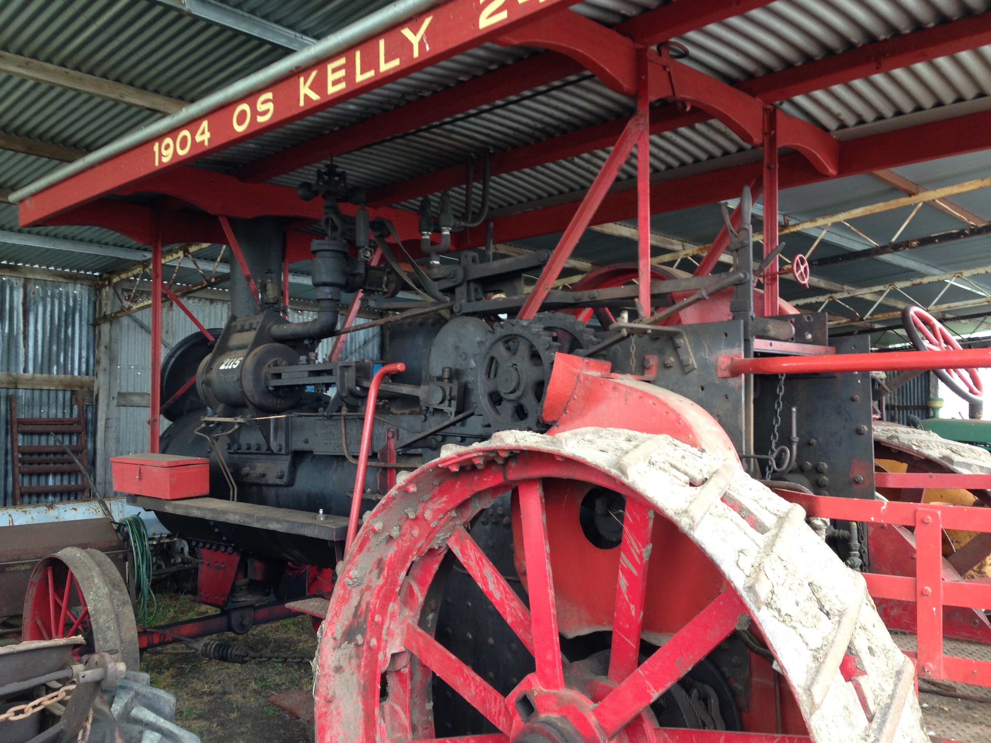
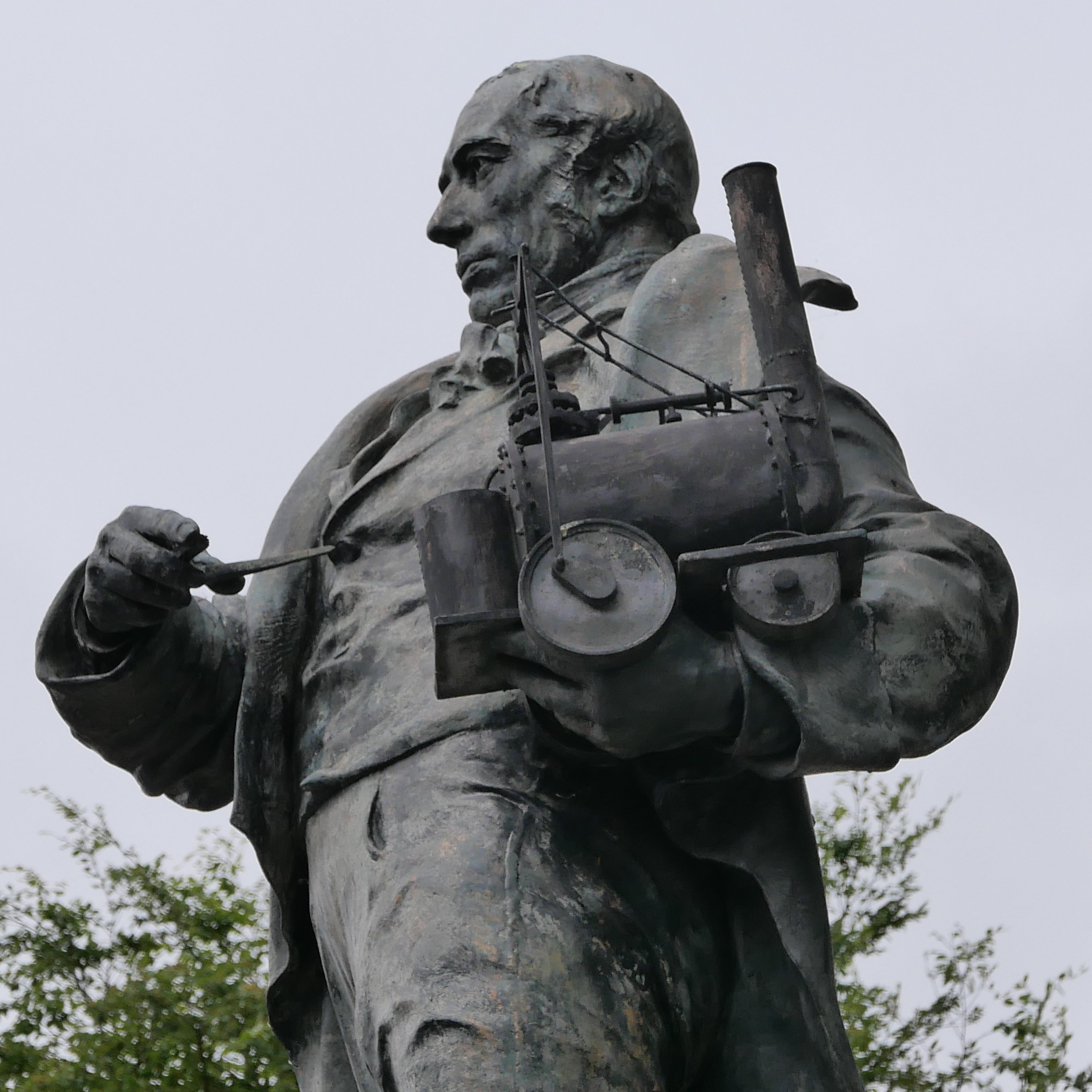
Tin and copper mining continued in Cornwall until very recently.  I am not aware of any commercial mines currently operating.   But the evidence of mining in the 18th, 19th and 20th centuries is everywhere to be seen in the form of smoke stacks, and engine houses, which once housed mighty steam engines.  In the past 2 days I have visited 3 mines, which have differing approaches to tourists.  They were The “King Edward Mine Museum”, “Geevor”, and “The Levant”.  I did photograph Ding Dong from a distance, because that was the mine of which Richard Trevithick was the captain.

King Edward Mine Museum.  Although the site of a mine, this is a museum of mine engines, boilers, and machines to separate the tin ore from the parent granite.

P1021685

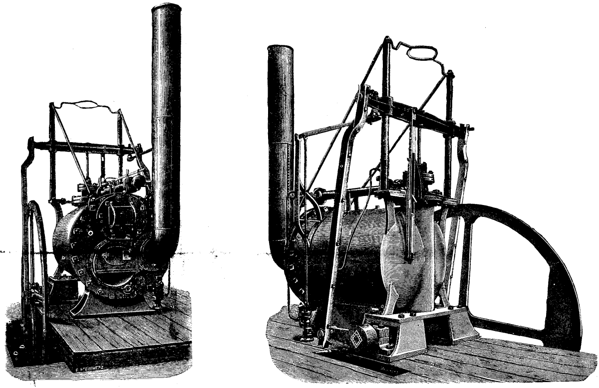
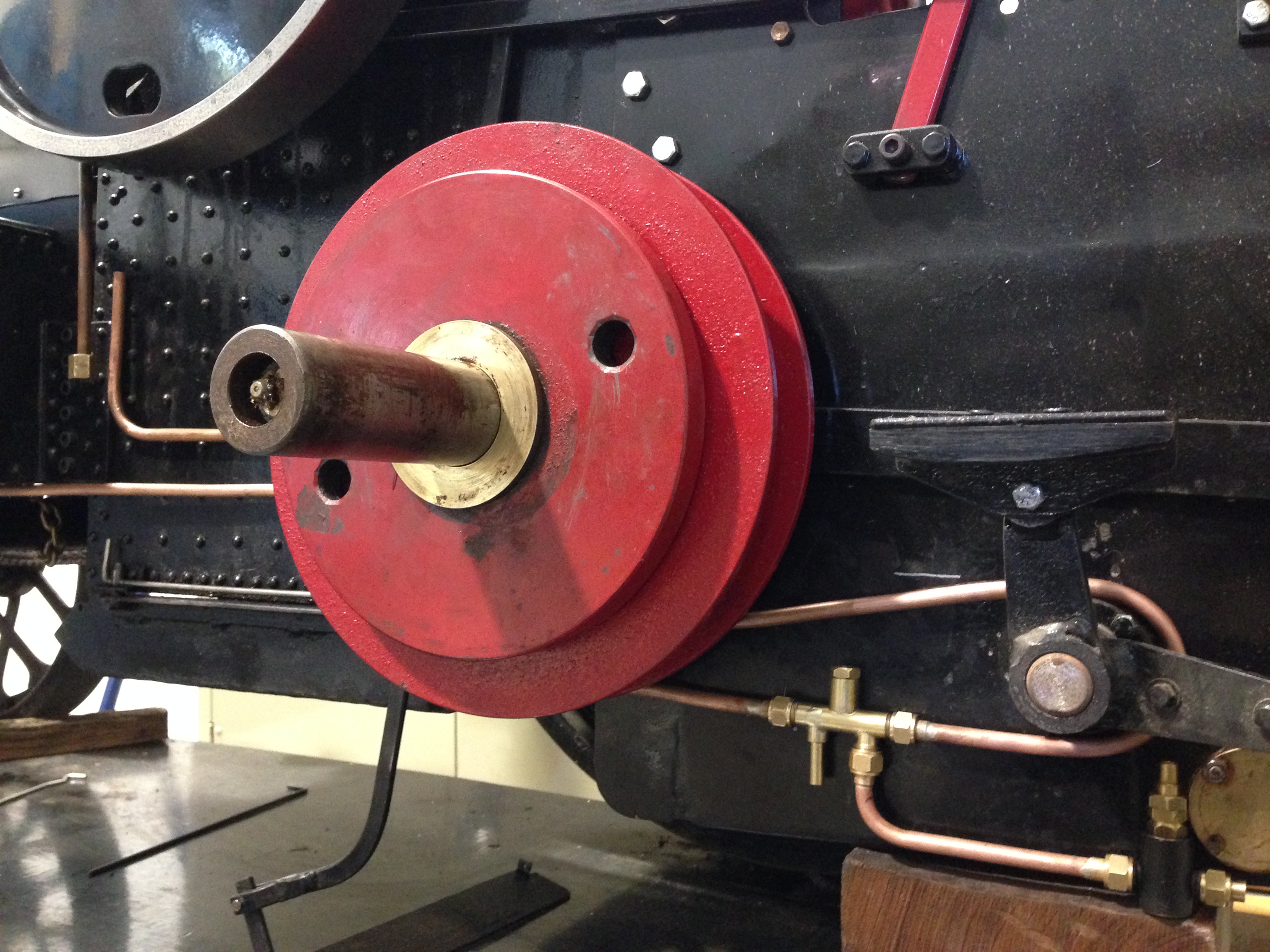
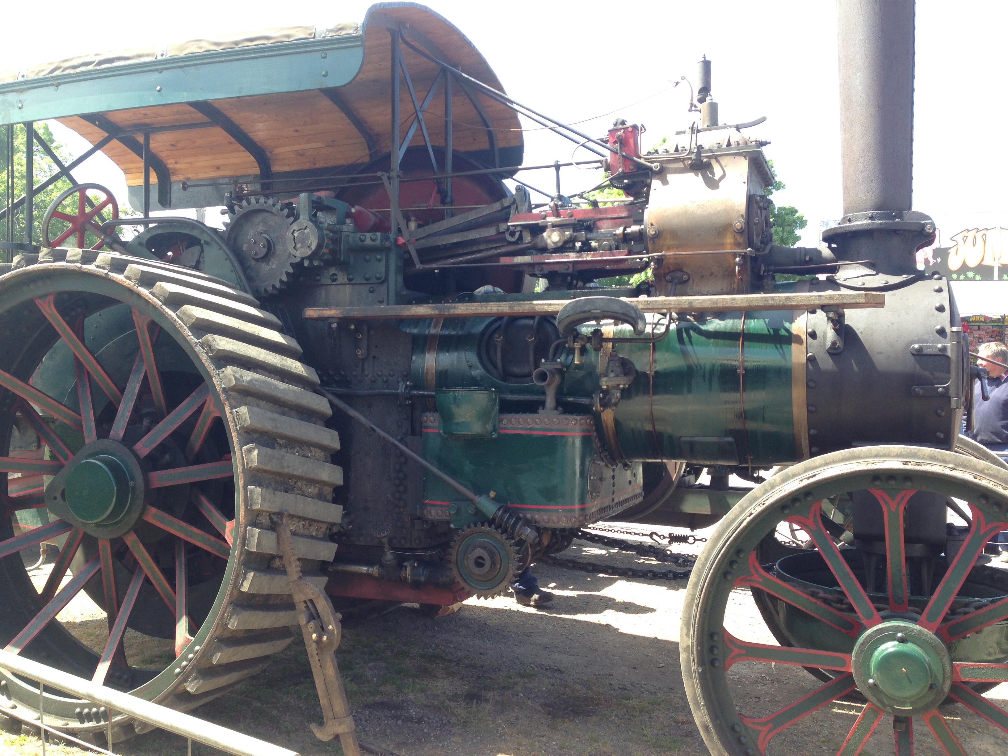
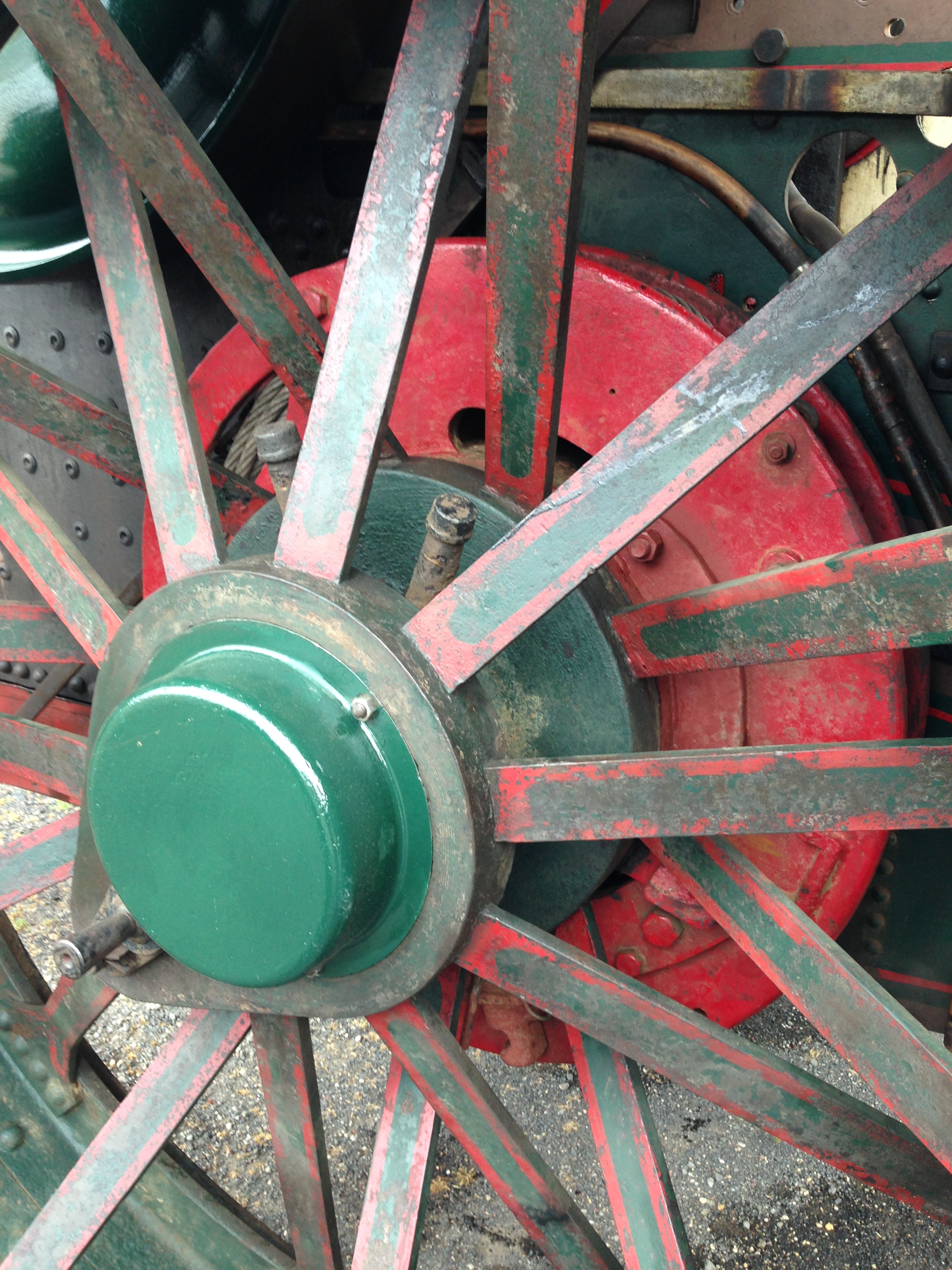
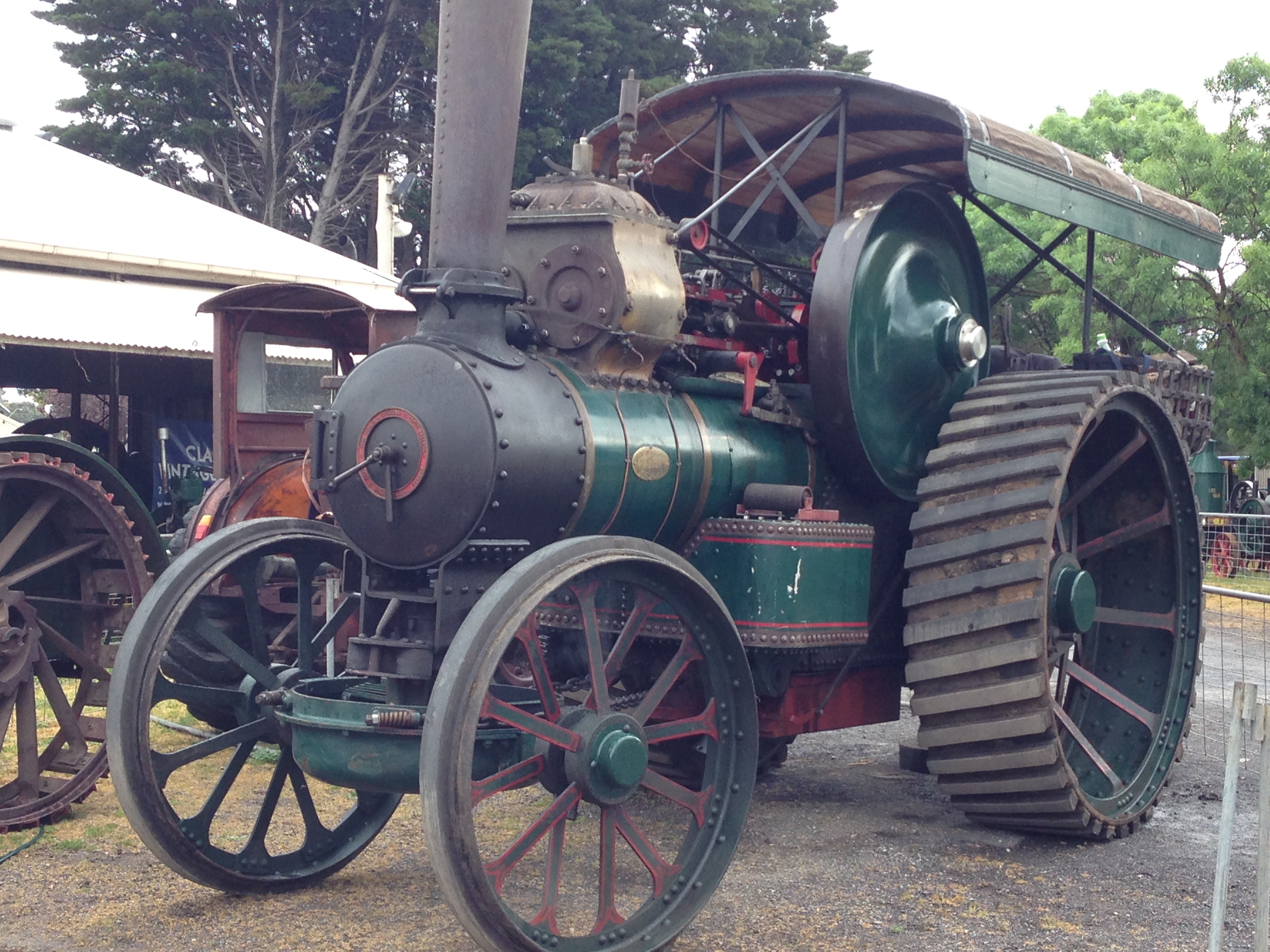
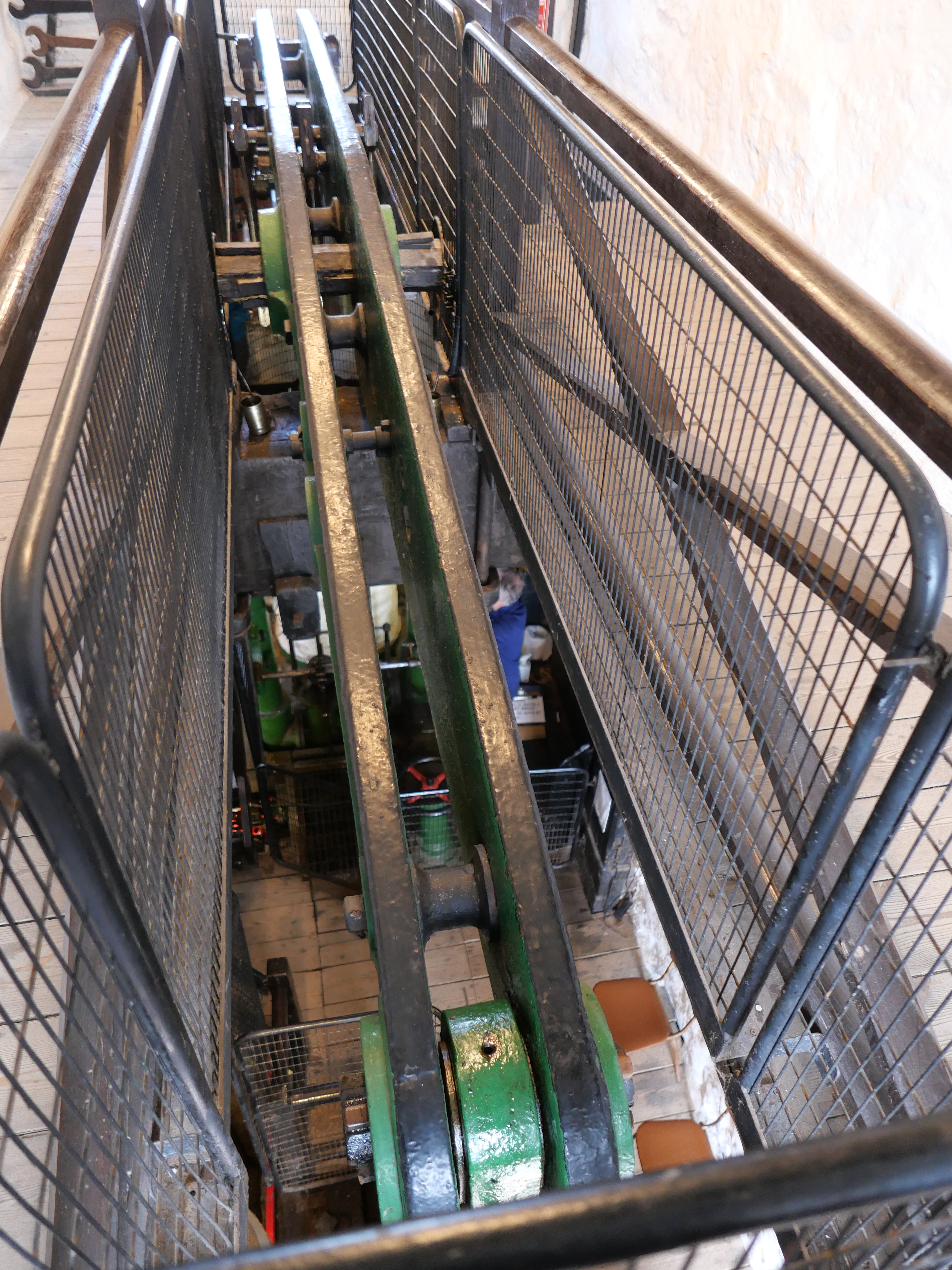
From a steam beam engine which provided power for the winding winch, the beam and connecting rod.

P1021671.JPG

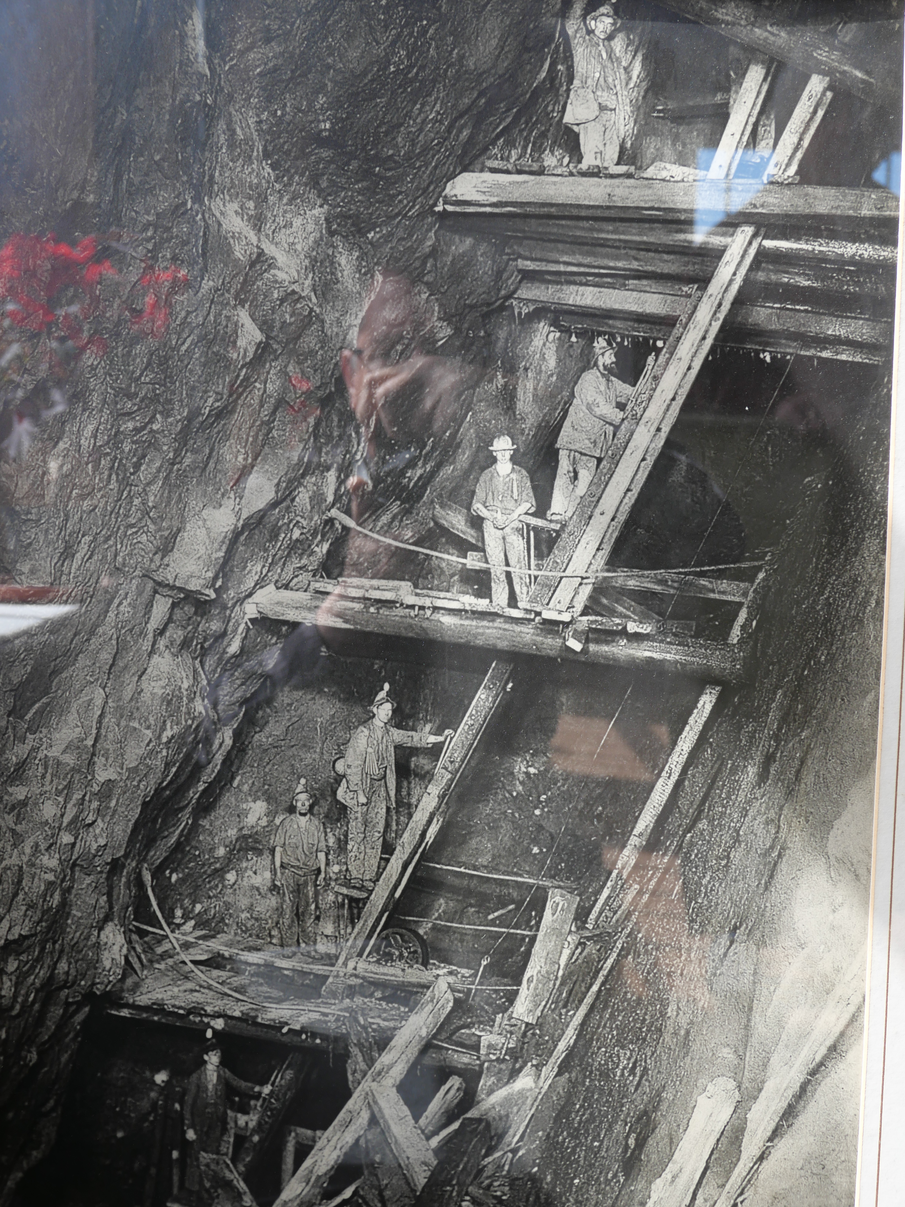
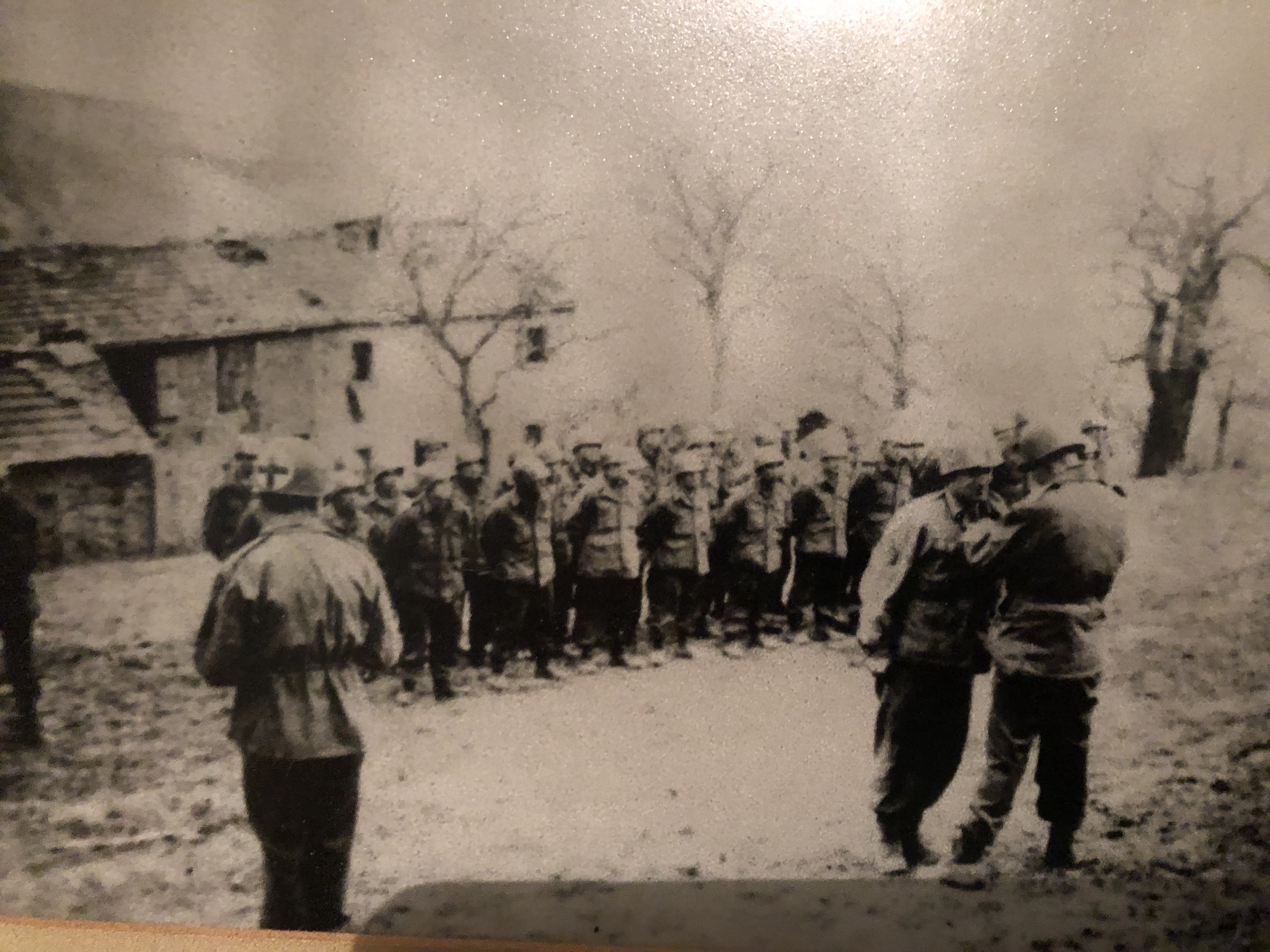
19th century photo of miners on a “man engine”.  To decrease the time it took for miners to climb up and down ladders, sometimes up to 2000 feet(!) to get to and from the working face, this was devised.  There is a series of wooden beams, fastened together end to end, totalling the length of the depth of the mine, and every 12 feet there is a small step.  A steam engine at ground level raised and lowered the wooden beams and steps every few seconds by 12′.   The miner had to step onto the moving step, be raised 12′ then step off onto the platform above.  Perfect coordination and timing was required.  Even using the engine, it would take 30 minutes to go up or down 2000 feet.  Needless to say it was dangerous, and many injuries, amputations, and some deaths occurred from miscalculation.  There was a disaster at the Levant Mine where the main beam broke, killing 31 men who were on the man engine.  OH&S is not total BS.

P1021683

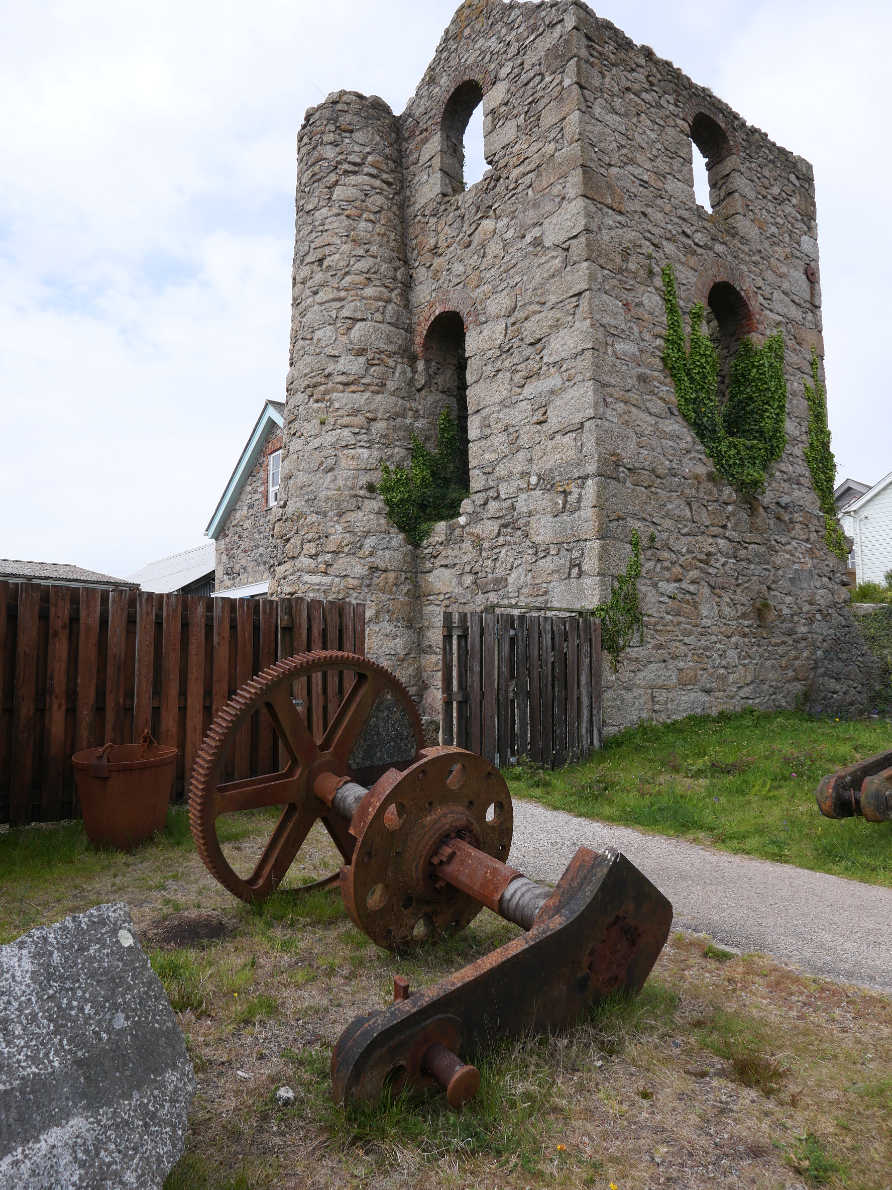
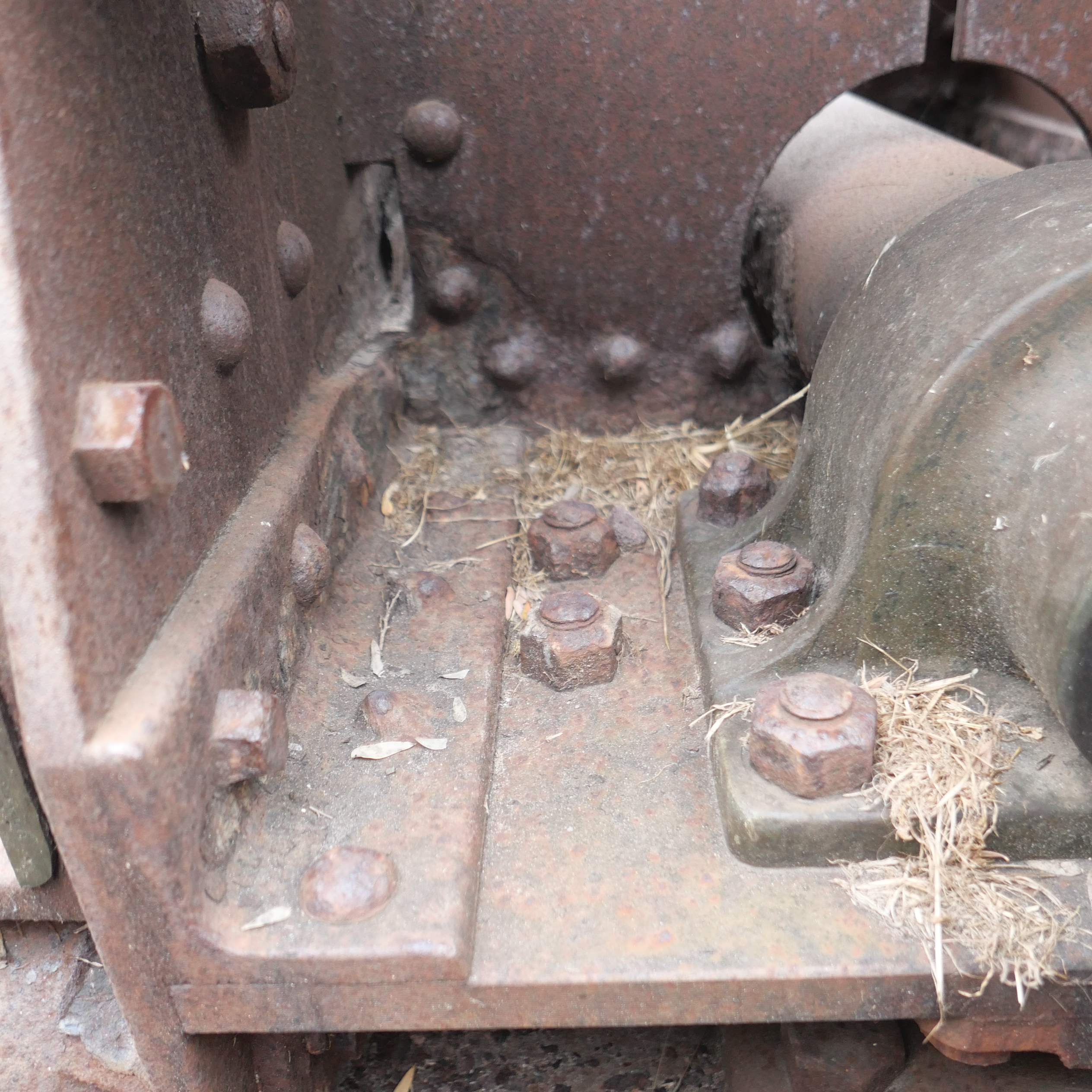
The remains of the engine house and chimney at King Edward Mine.  Granite blocks were preferred to hold the weight of the large beam engines.  And the beam weight was taken directly by the walls.

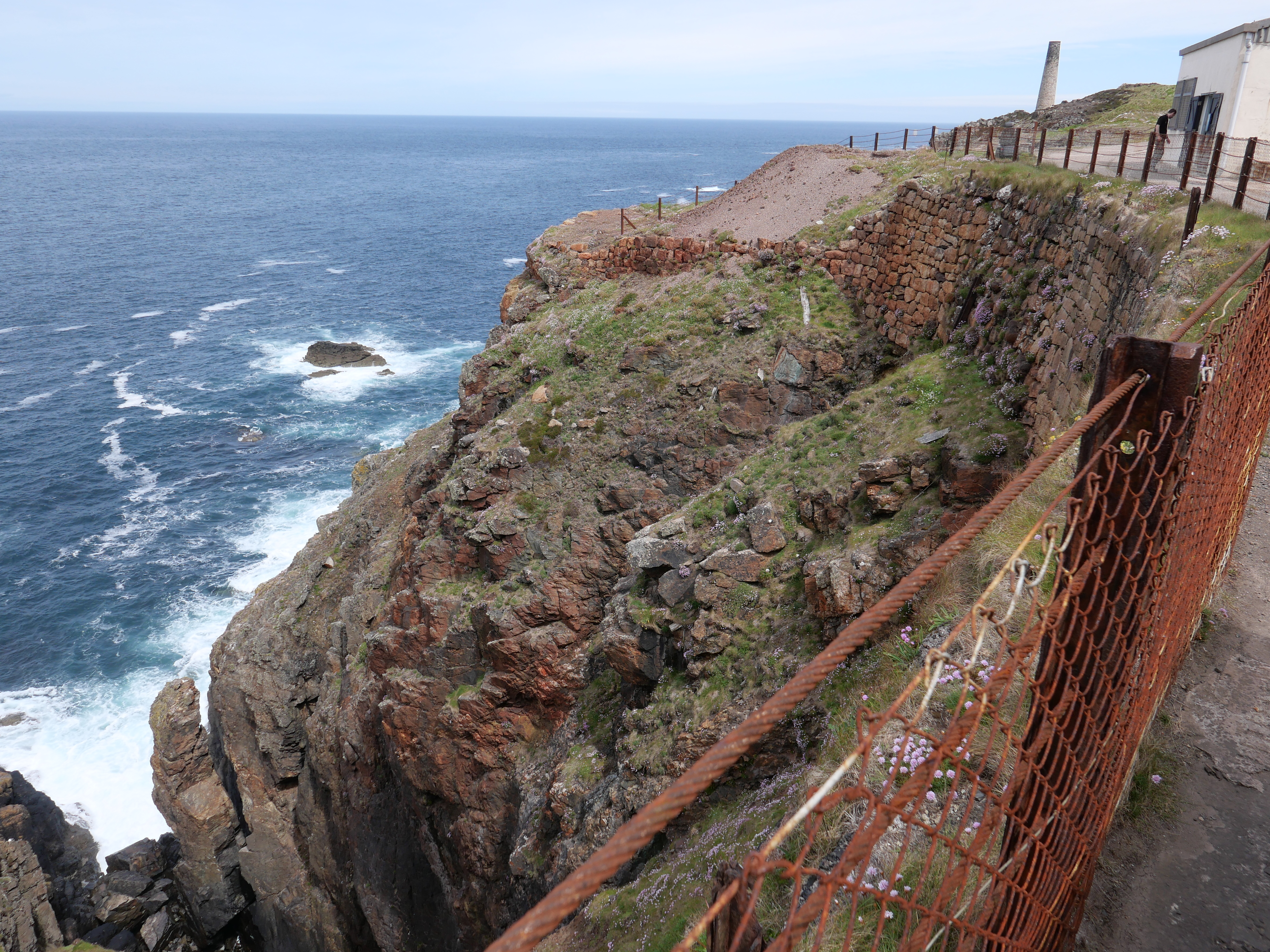
Geevor Mine closed later than King Edward, and the ore processing machines are substantially intact, and date from early 20th centuery.  It is on the coastline of Cornwall.

P1021706.JPG

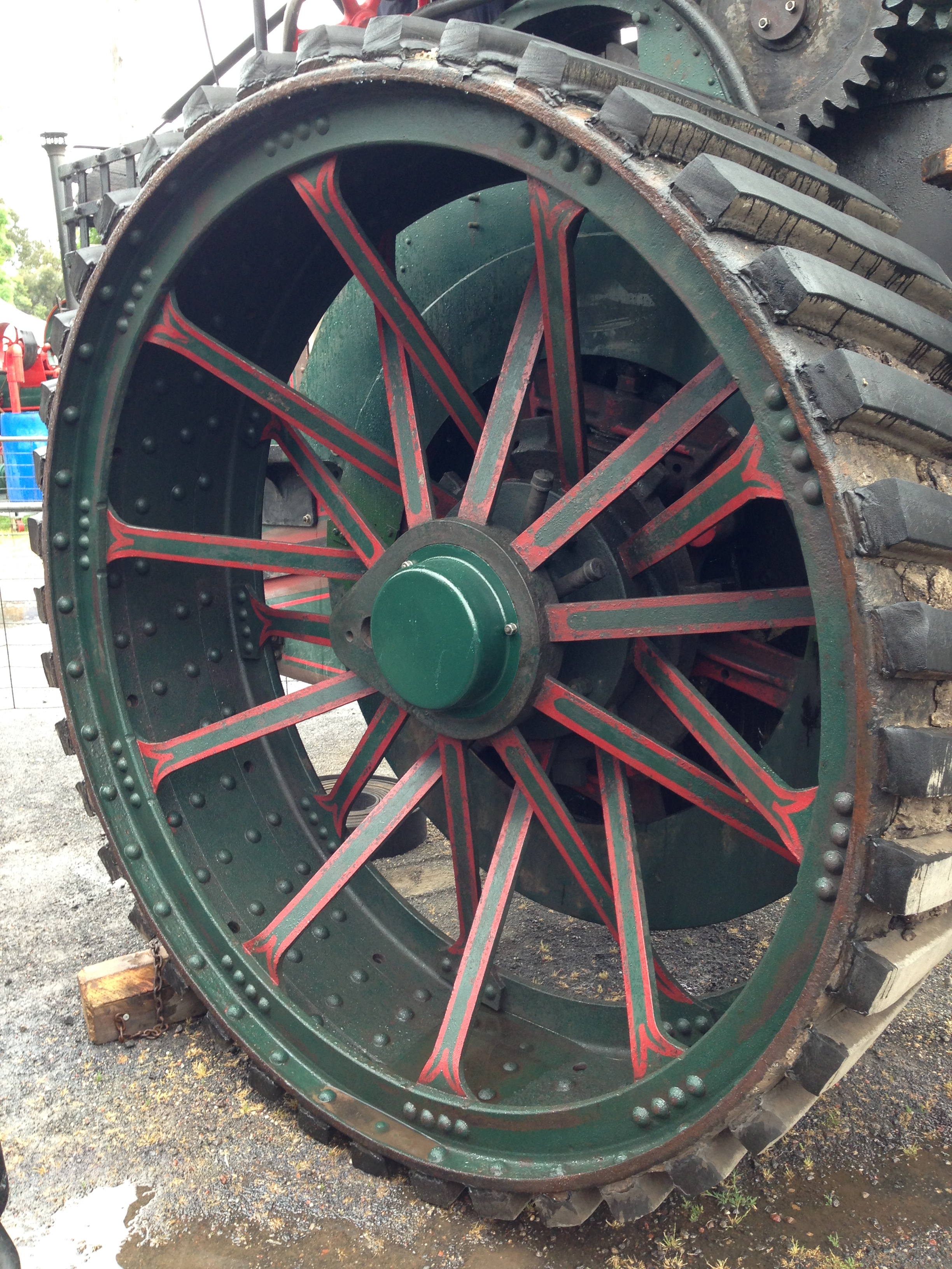
Geevor Mine.  The tower with the wheels is the headframe.  The engine house is on the right.

P1021719

Like gold sieves, the denser tin ore is sieved from the lighter rocks.  The bottom machines are a last phase of grinding.

P1021714.JPG

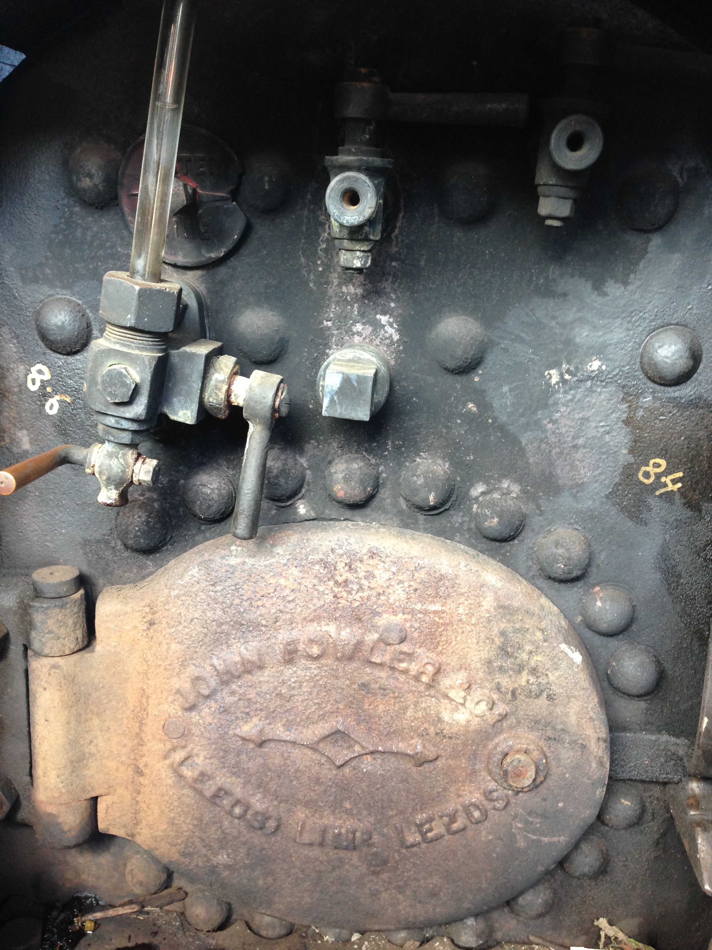
Boilers.  Lancashire type I think.  (my bad.  Not Lancashire.  Egg end

P1021715.JPG

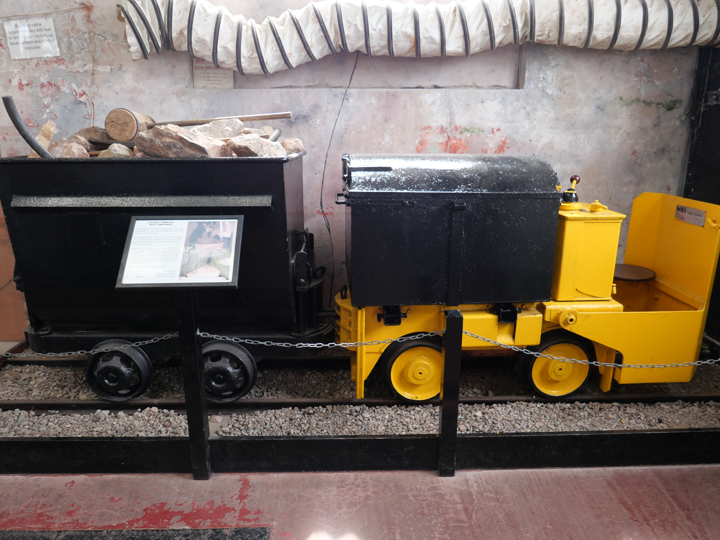
Ore train, battery powered.  Earlier they tried small steam engines, but the smoke was a problem, so they used horses to pull the empty trucks back to the loading areas.  The loaded trucks went to the bucket lifts down a gradual slope, using gravity.  The horses spent 2 months under ground, and were carefully looked after because of their cost, and the trouble of getting them down and up.  At the end of two months they were blindfolded and legs tied, and were lifted using the ore lifting whim.  They were kept in a dark barn for 2 weeks, then allowed out for 6 weeks, before going undergound again.

P1021723.JPG

Water wheel powered ore crusher.

The final part of this tour, was a walk undergound, through a 350 year old mine, later used as an access tunnel.  They issued us with a helmet and raincoat, and both were absolutely necessary.  The tunnel was about 5′ to 5’6″‘ tall, so the helmet took a battering. The walls were wet, and the roof constantly dripped and ran.  Sometimes the walls were not vertical, but sloped markedly.  Our guide used to be a tin miner, and he told us that they disliked the irregular access, because after placing a charge of black powder, they had approximately 30 seconds to clear the area.  Falling over, or being too slow was a bad option.  And it was pitch black when the lights were out.  This tour is not for everyone.

Prior to pneumatic drills, water fed tools, the charge holes had to chiselled by hand.  One person holding and rotating the drill (chisel), and one or two miners swinging heavy sledge hammers.  Typically it would take 2-3 hours to chisel the 6-8″ hole to take the charge of powder.  They made their own fuses using goose quills end to end, and filled with black powder.   This was granite containing the tin ore.  Very hard stone.  Very few timber props were required once the mine was well undergound.


P1021703.JPG

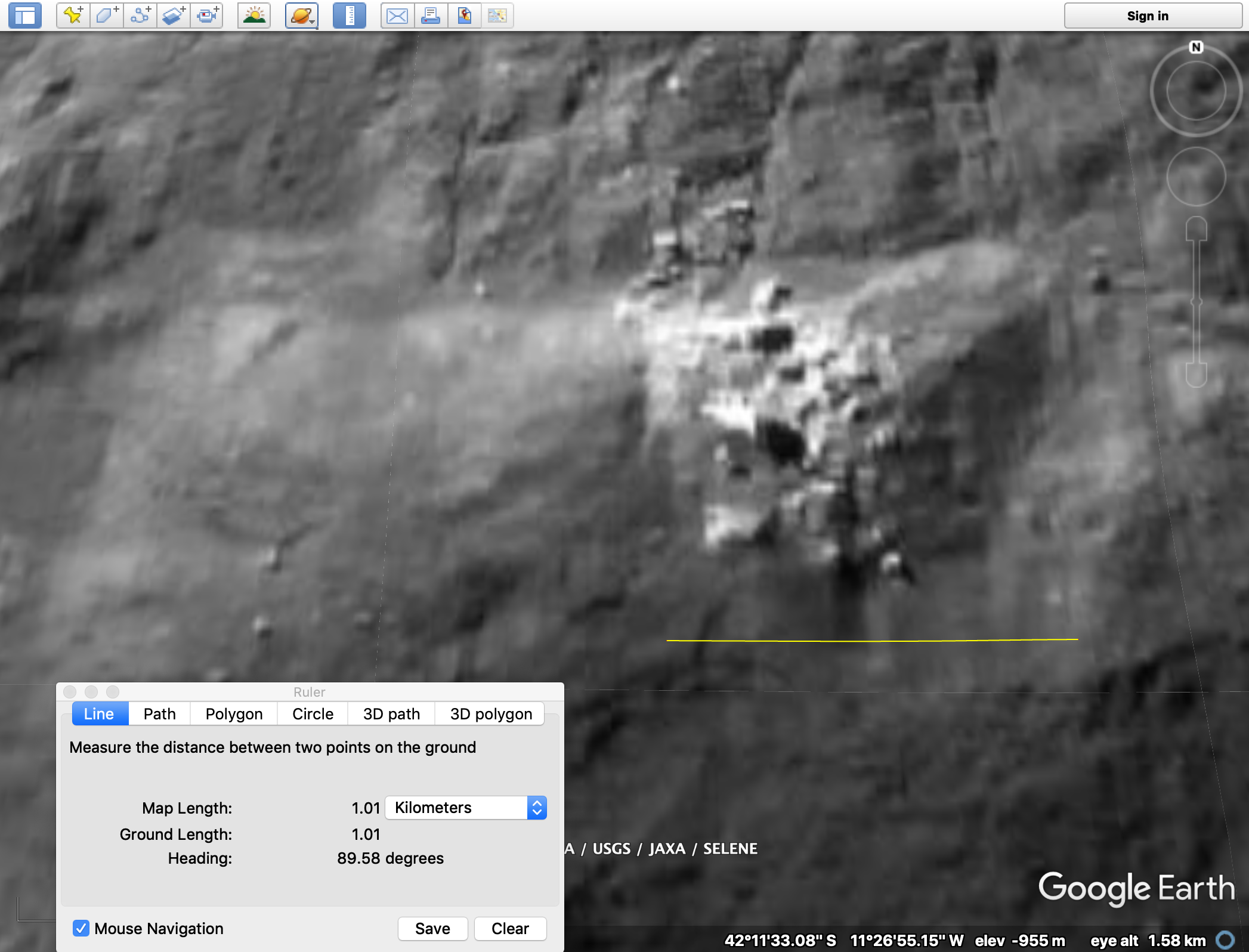
This is a 3D model of one mine’s shafts, adits, and tunnels.   100 miles altogether.  2000 feet deep, and extending inland, and out under the ocean floor for 2000 feet!   Surprisingly, the part under under the ocean was the driest, and was fresh water, except when they accidentally mined up too far.

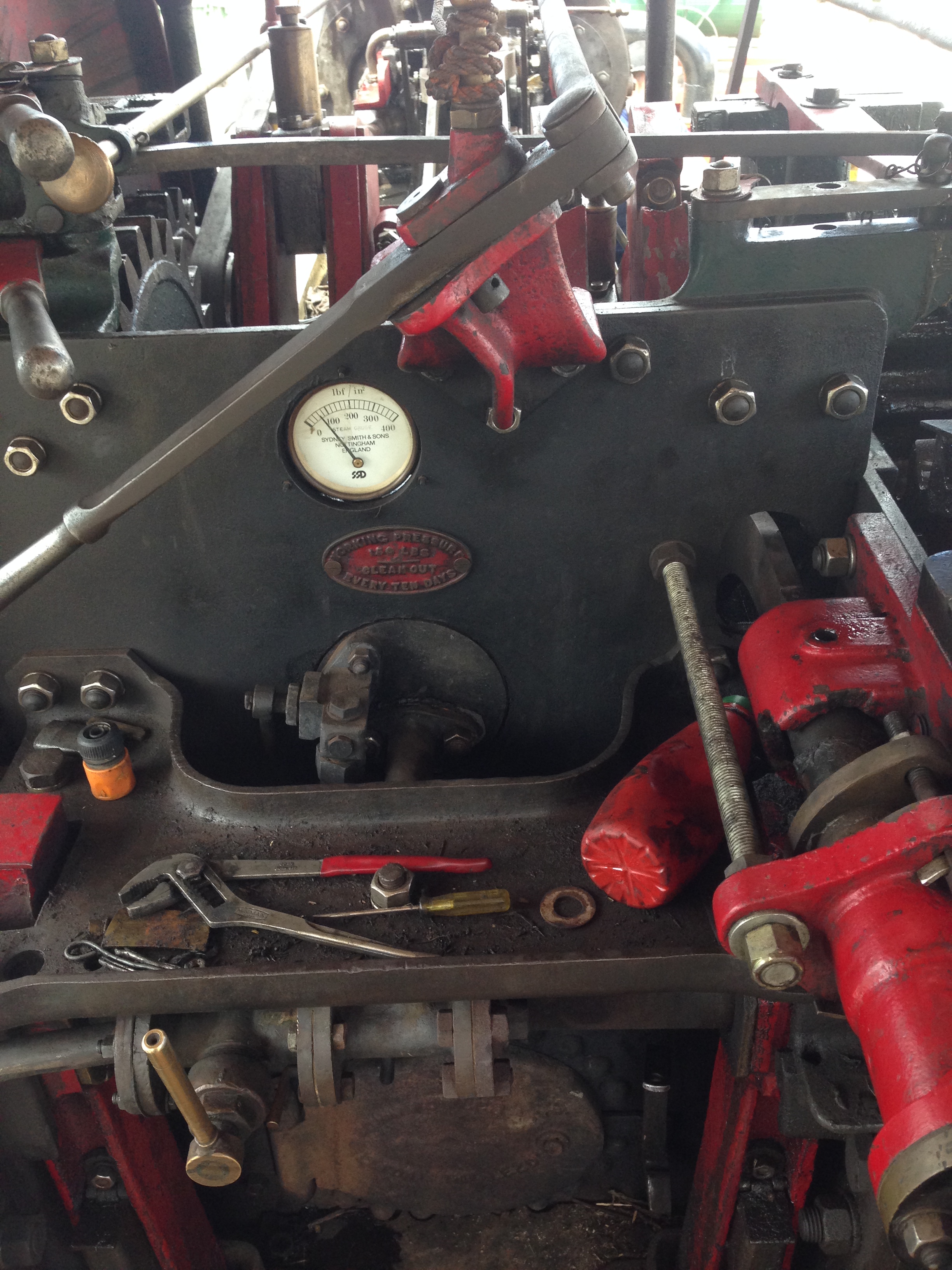
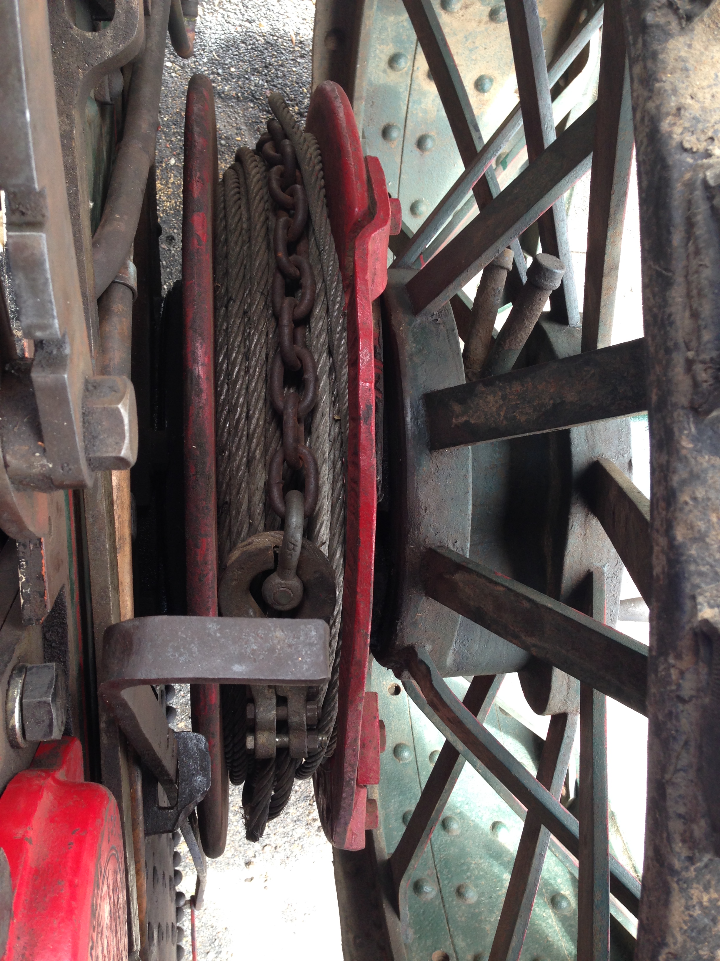
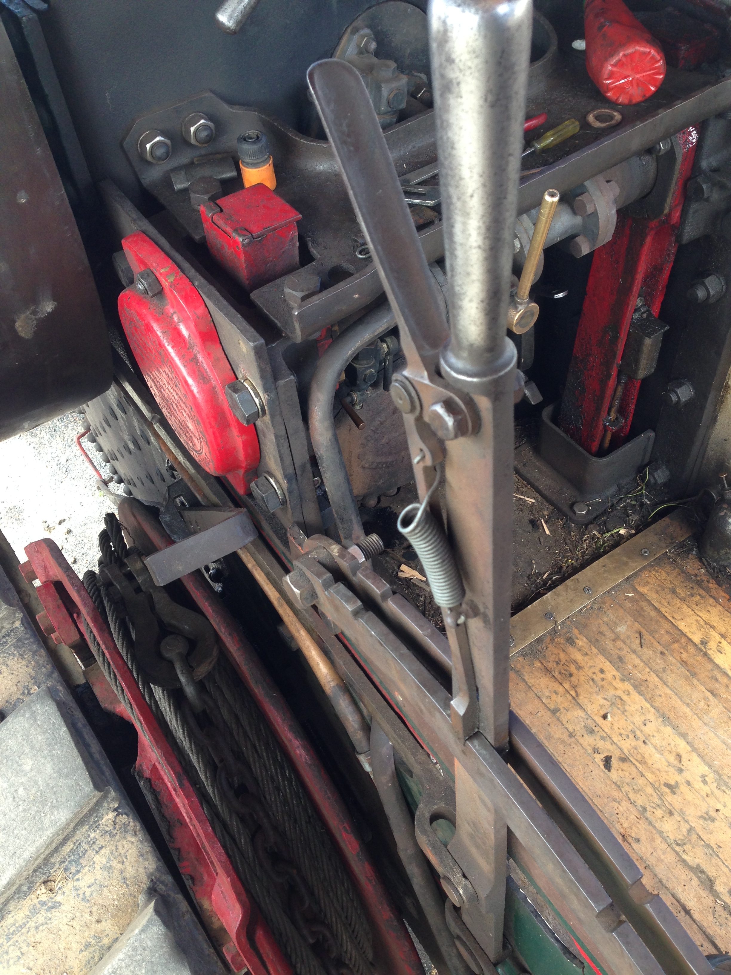
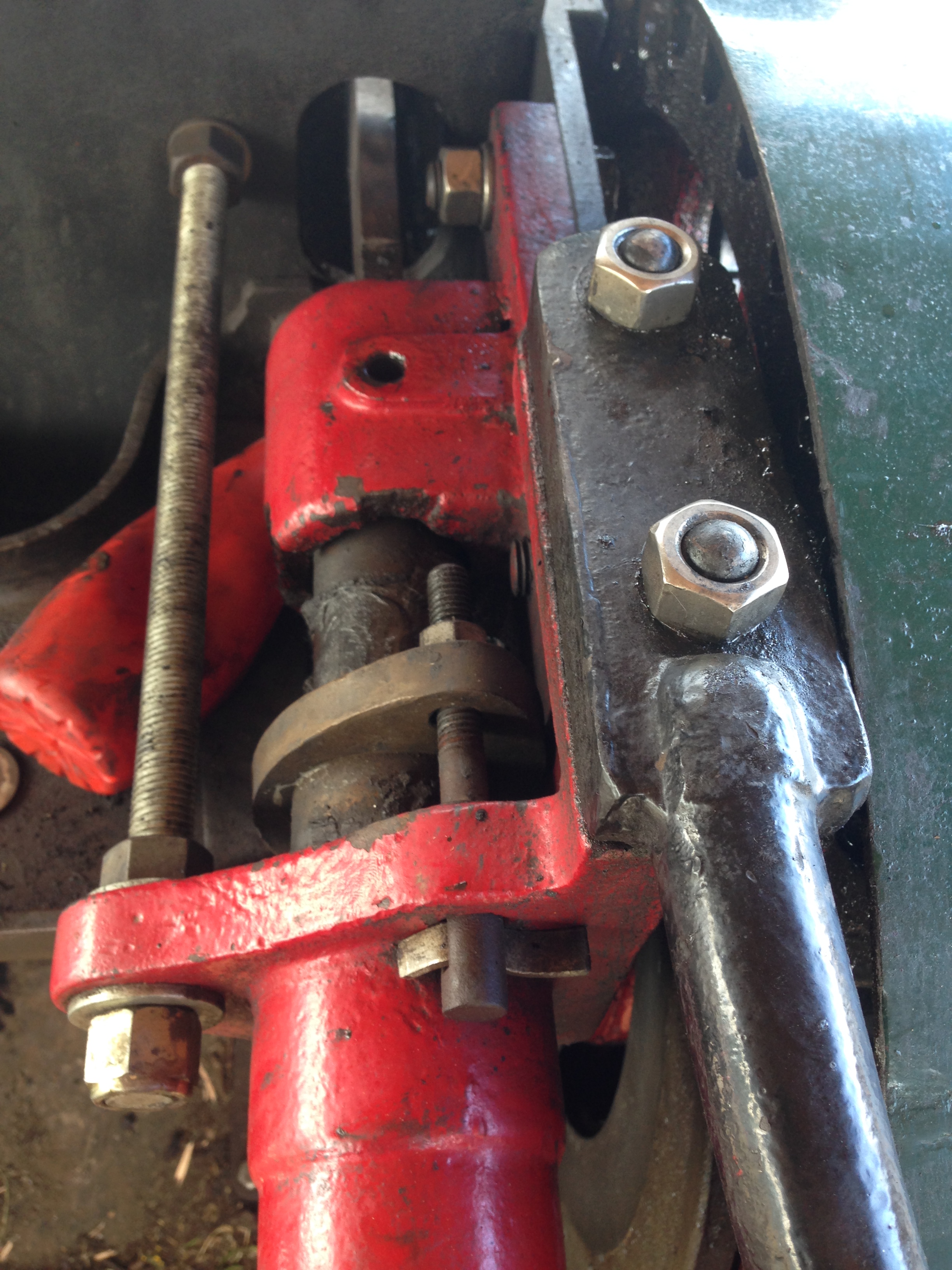
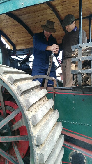
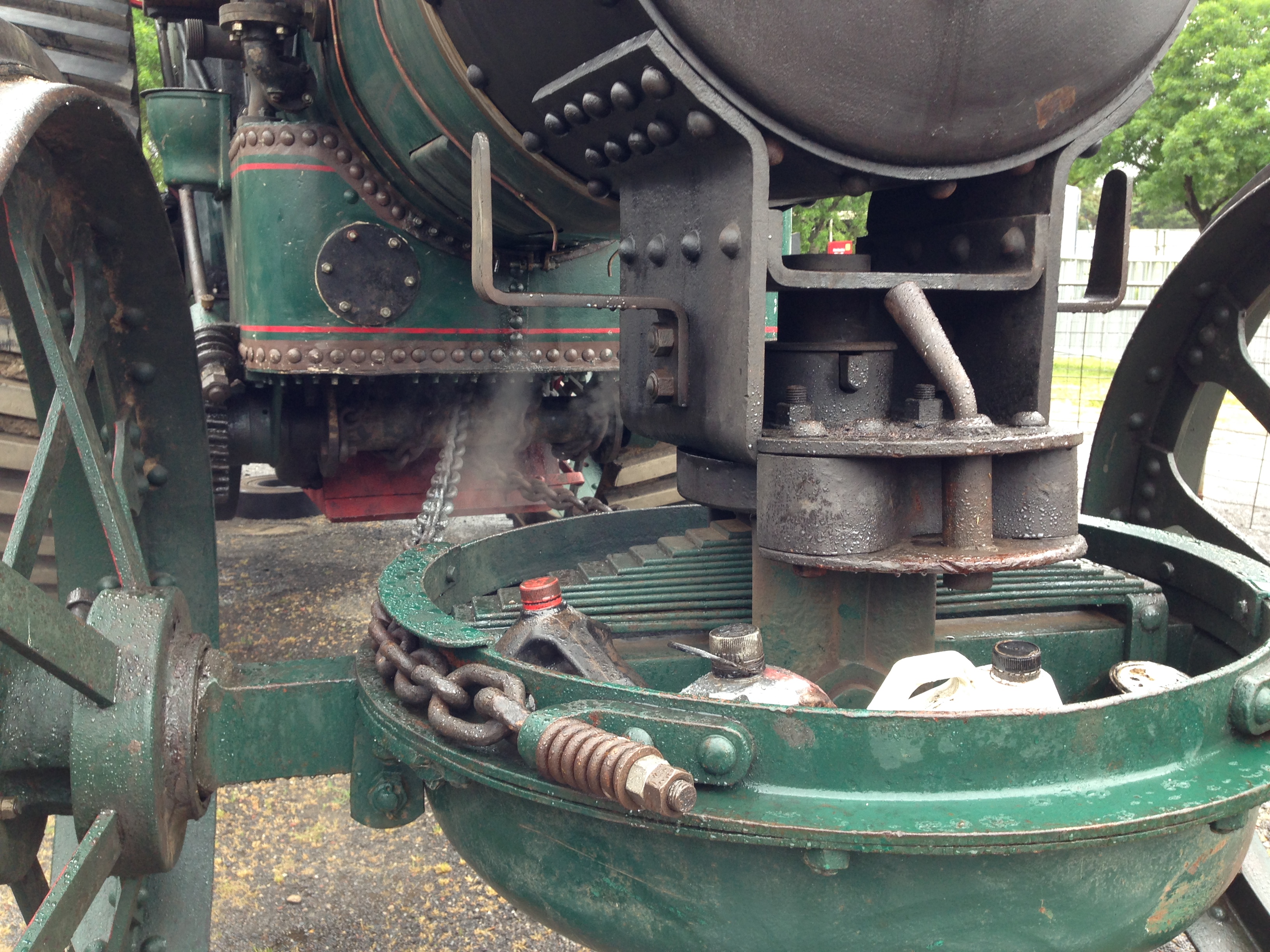
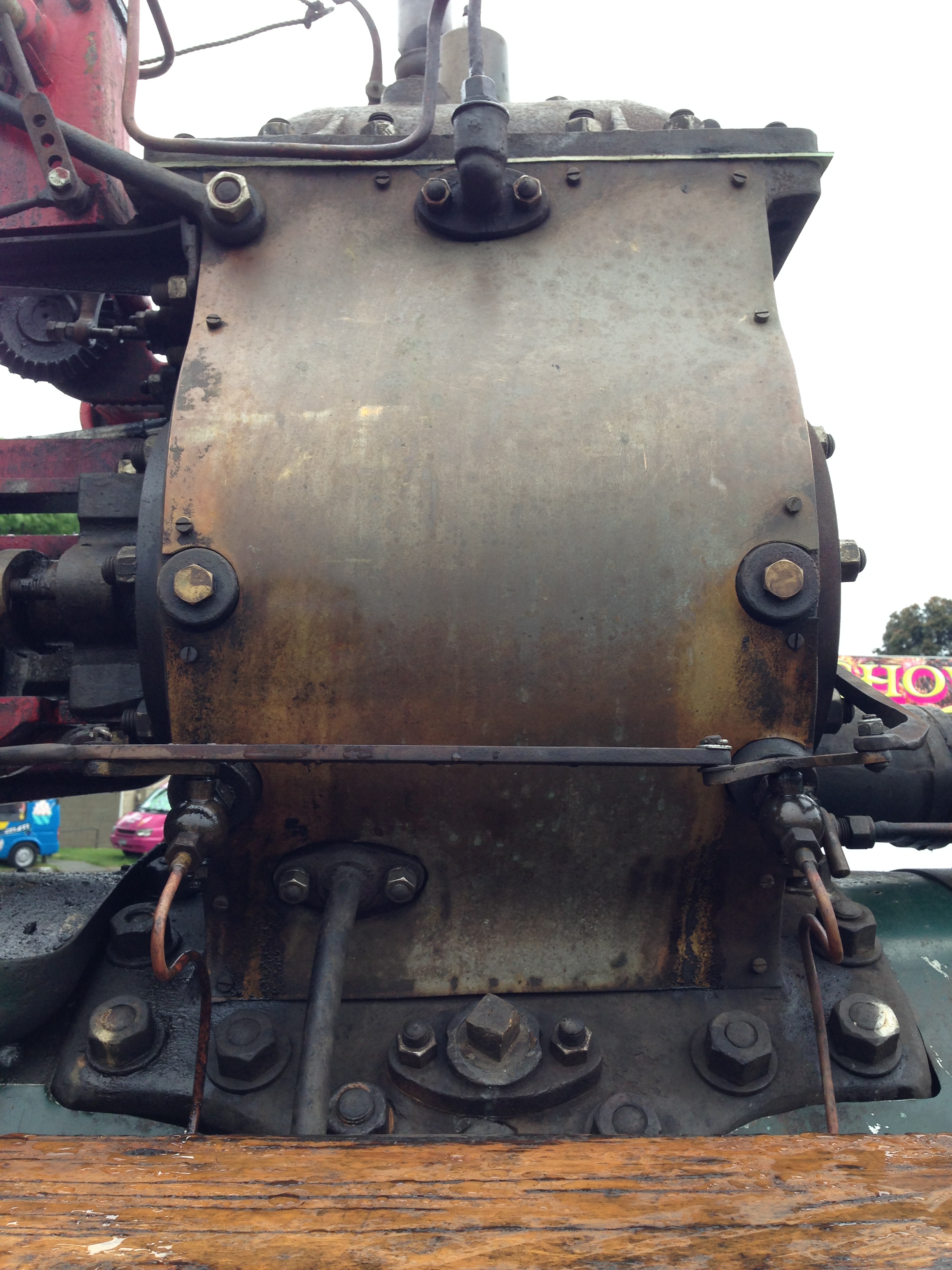
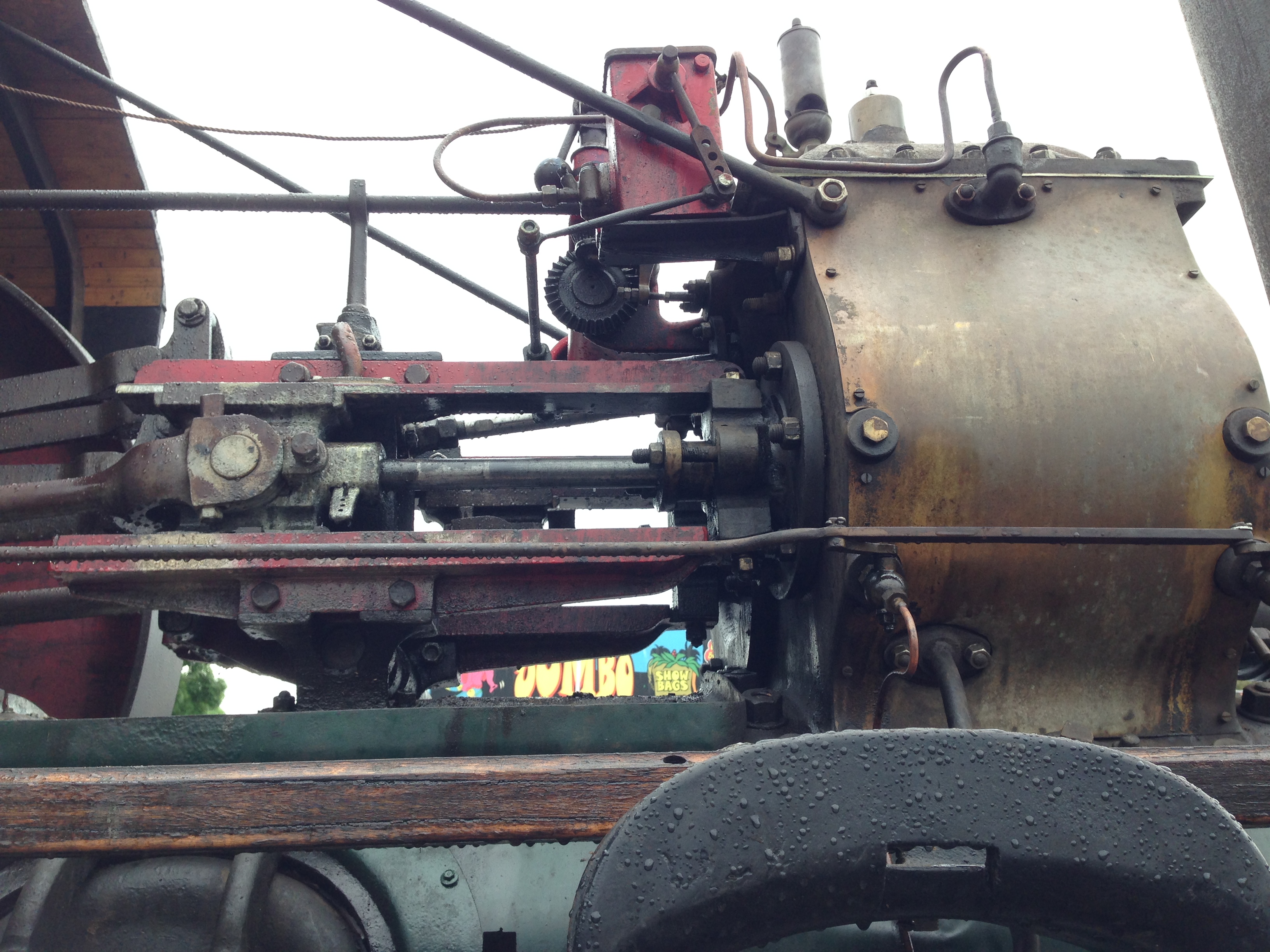
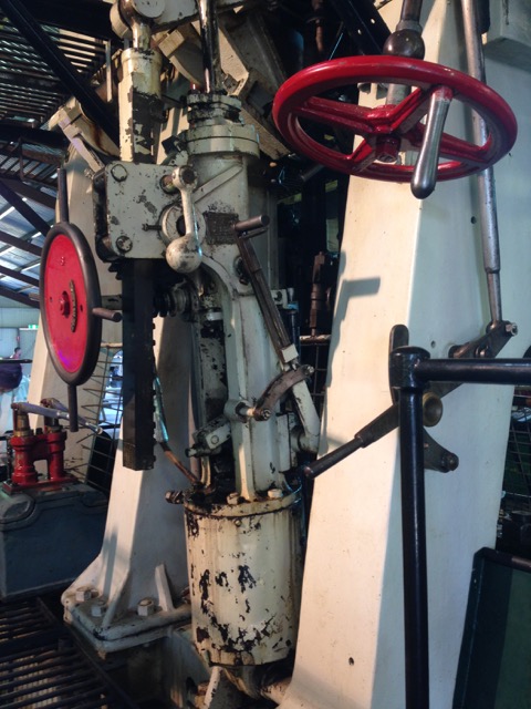
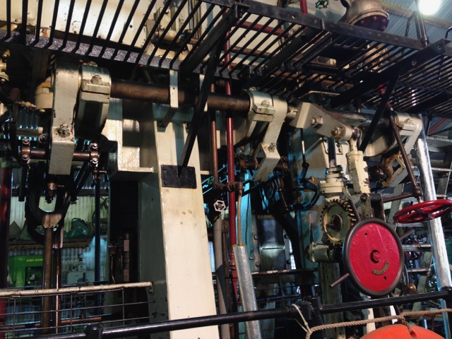
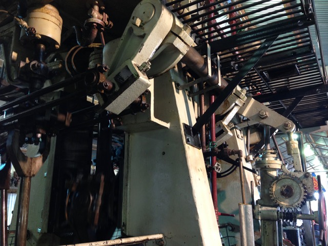
The final mine which I toured was the richest.  The Levant mine.  It is of great antiquity.. 3000 to 600 BCE and intermittently mined until 1930.  It never really recovered from the Man Engine disaster of 1919.  It is now a National Trust site, and the tour was one of the best I have experienced anywhere.  Again the tour guide was an ex tin miner.  He looked the part, with missing teeth,  west country brogue, and built like a T34 tank.  He was a superb raconteur, with a wealth of stories and knowledge, and answered every question with assurance.  We visited many parts of the complex, including a trip into a mine, with a huge vertical shaft at the end.  Counted the tourists in and out, and radioed the manager in and out.  The tour ended with a visit to the steam driven whim engine.  It was the only engine saved after the closure.  The rest were scrapped.


P1021744.JPG

Levant mine is perched on top of rugged Cornish cliffs.  The cliffs were mined by ancients.  The adit (water drainage tunnel and mine entry is down near sea level.  We did not venture down there) opens near the bottom left of the pic.

P1021737

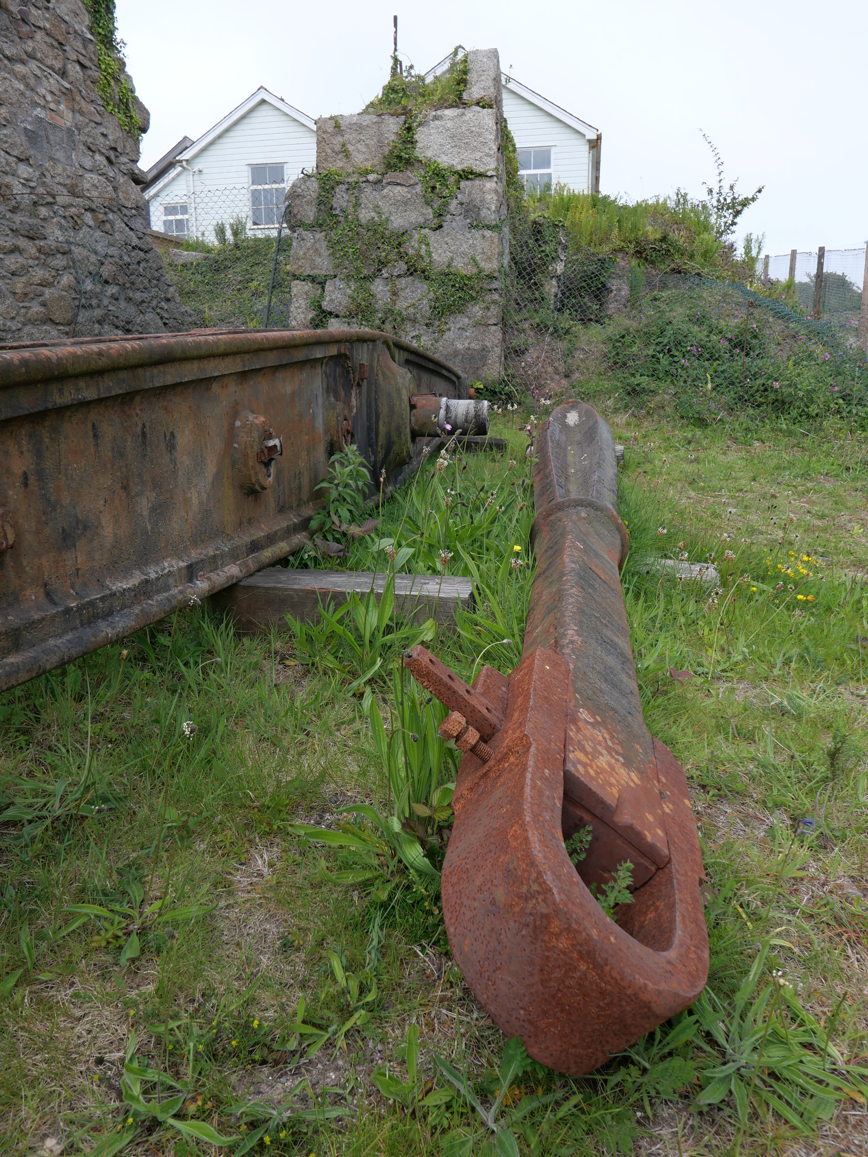
A small part of the Levant above ground complex.


P1021763.JPG

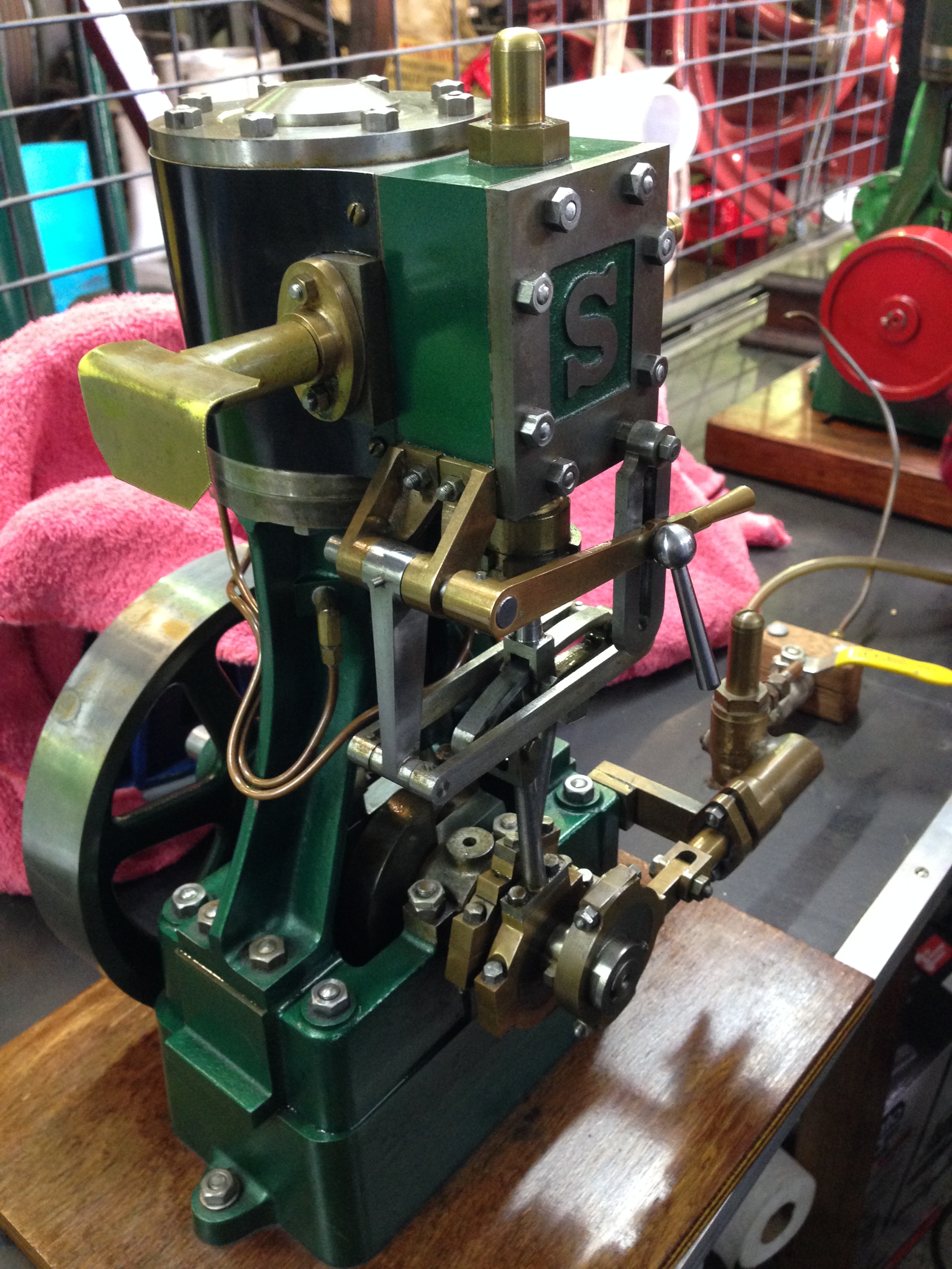
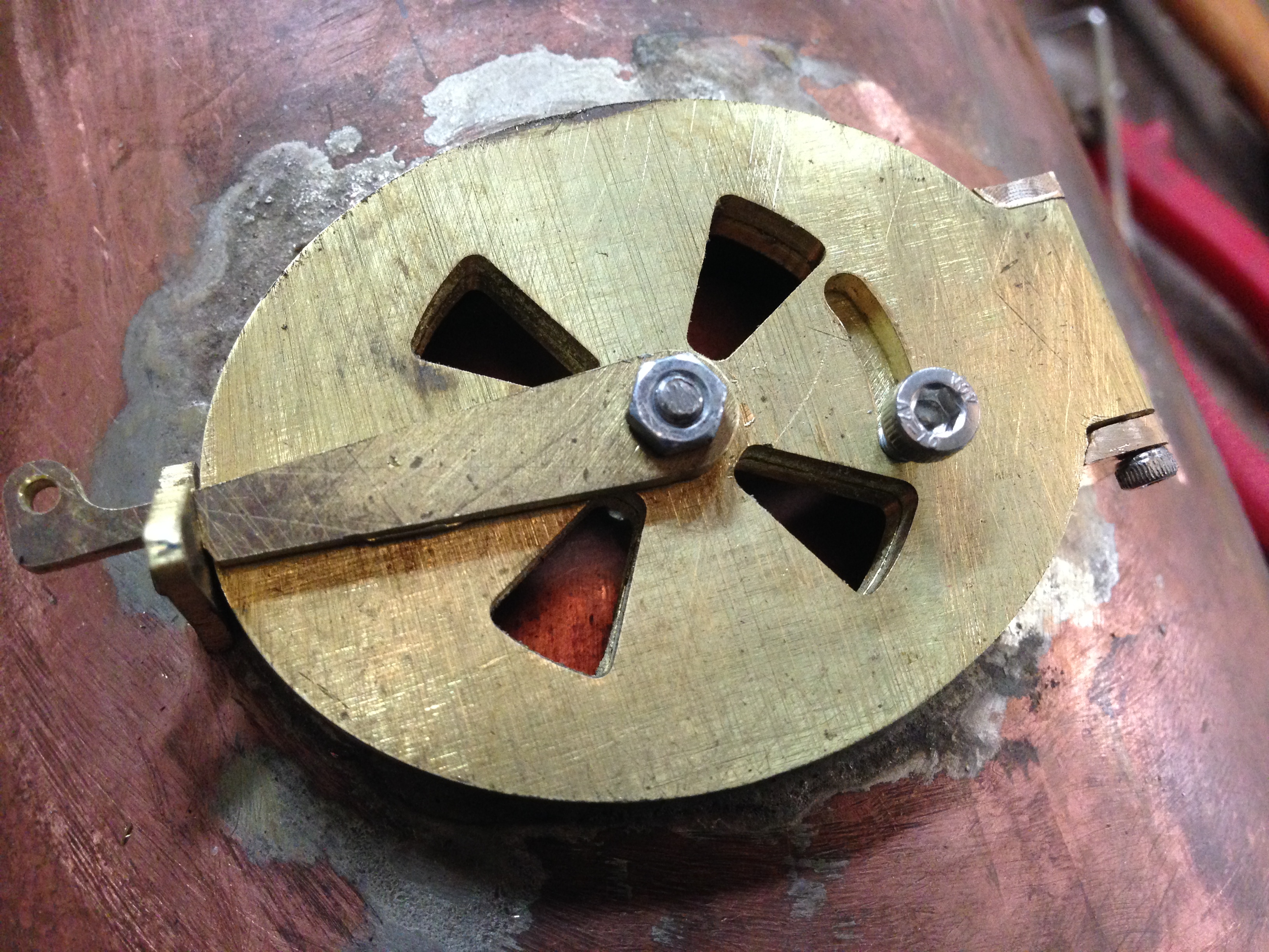
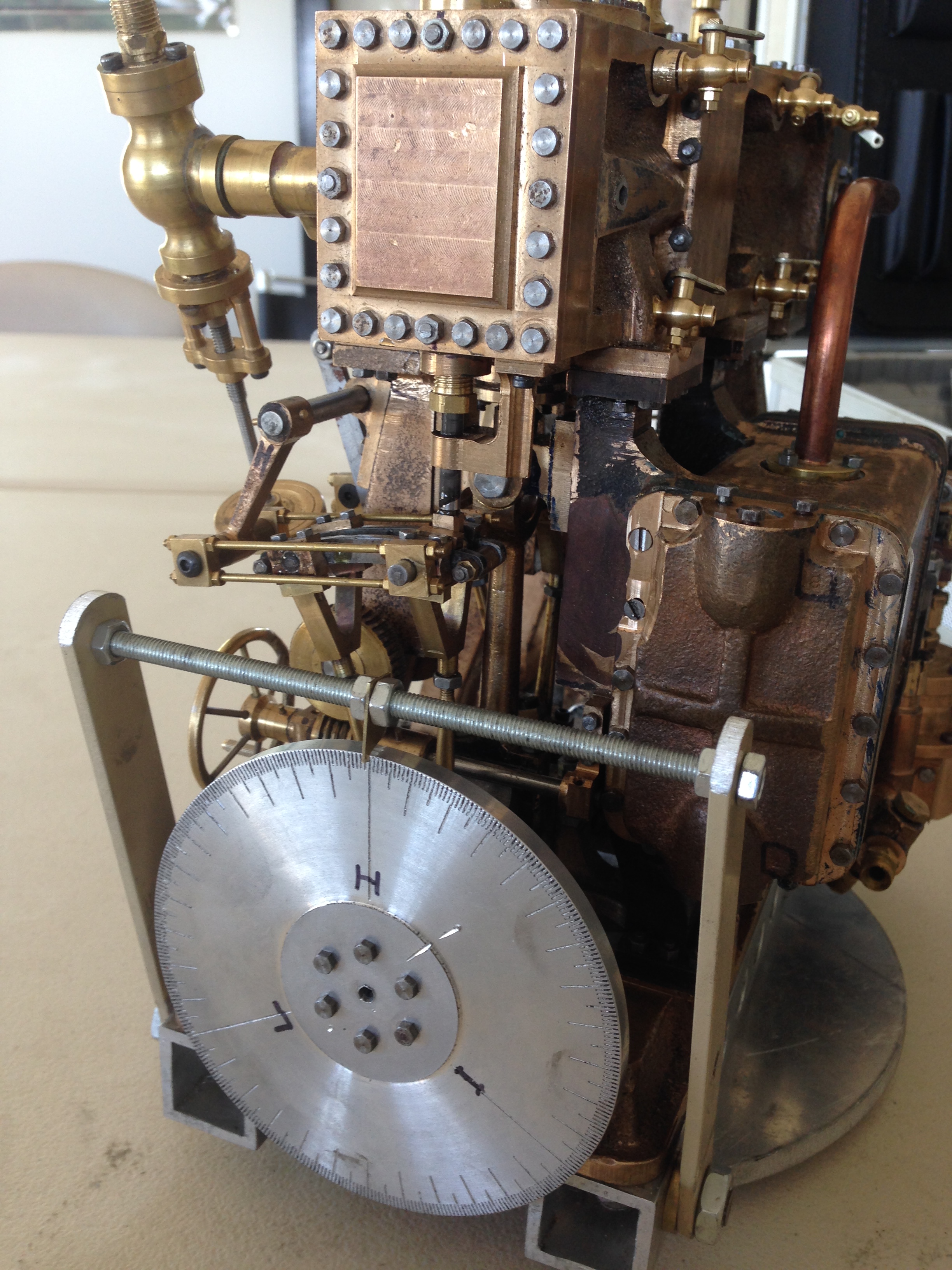
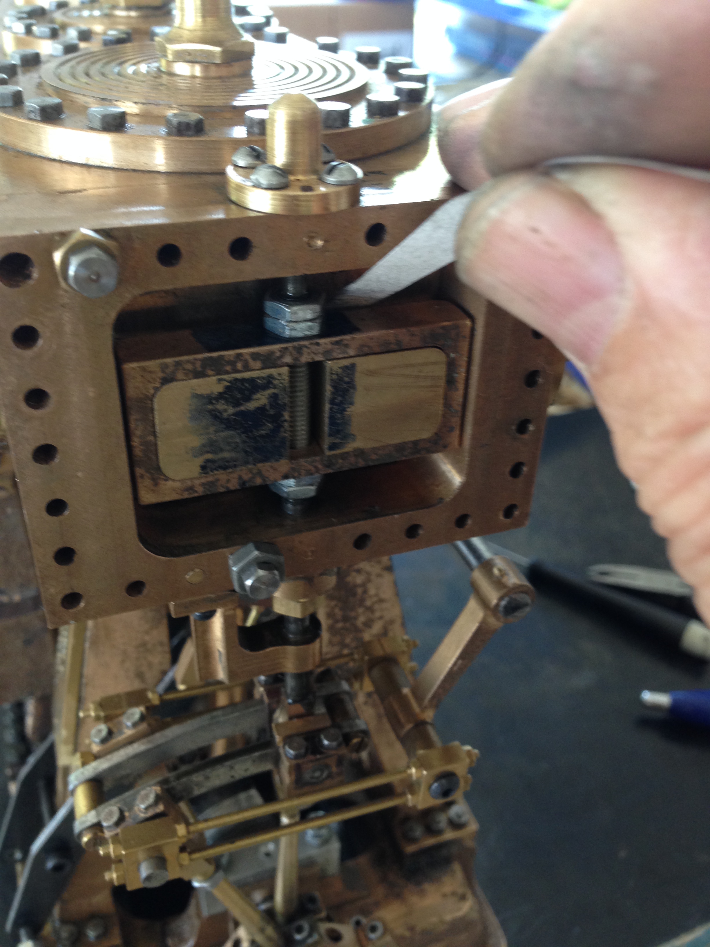
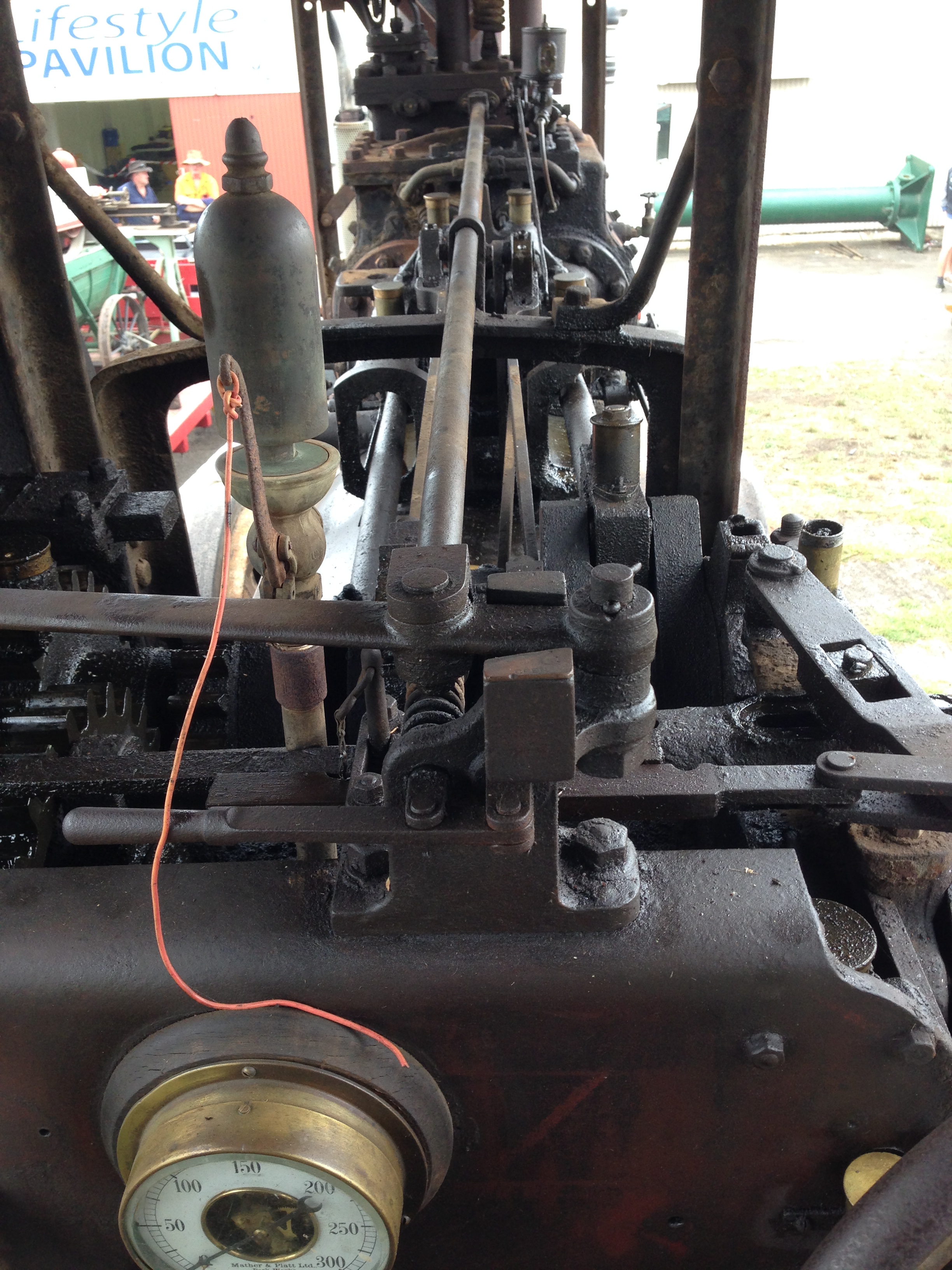
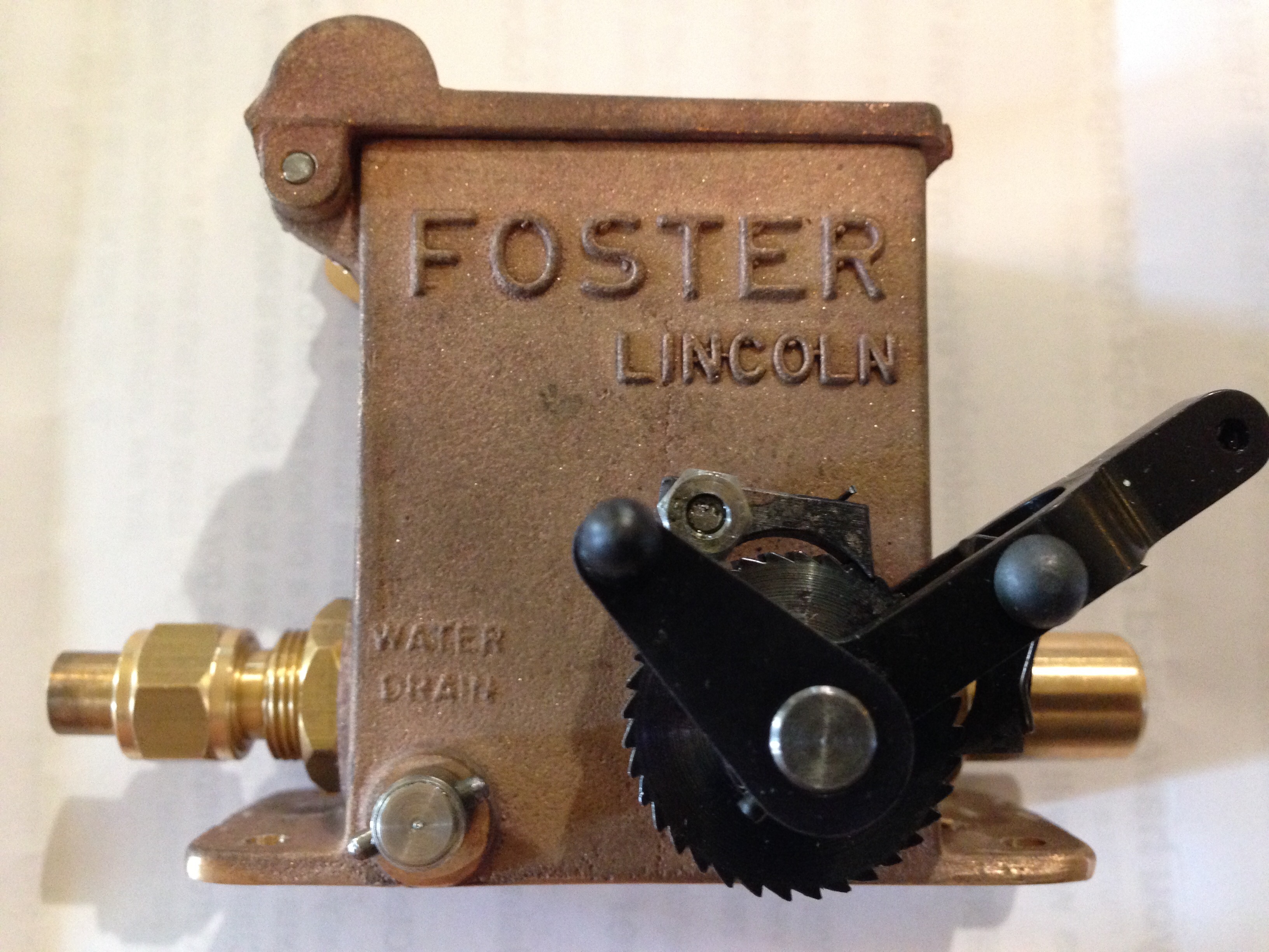
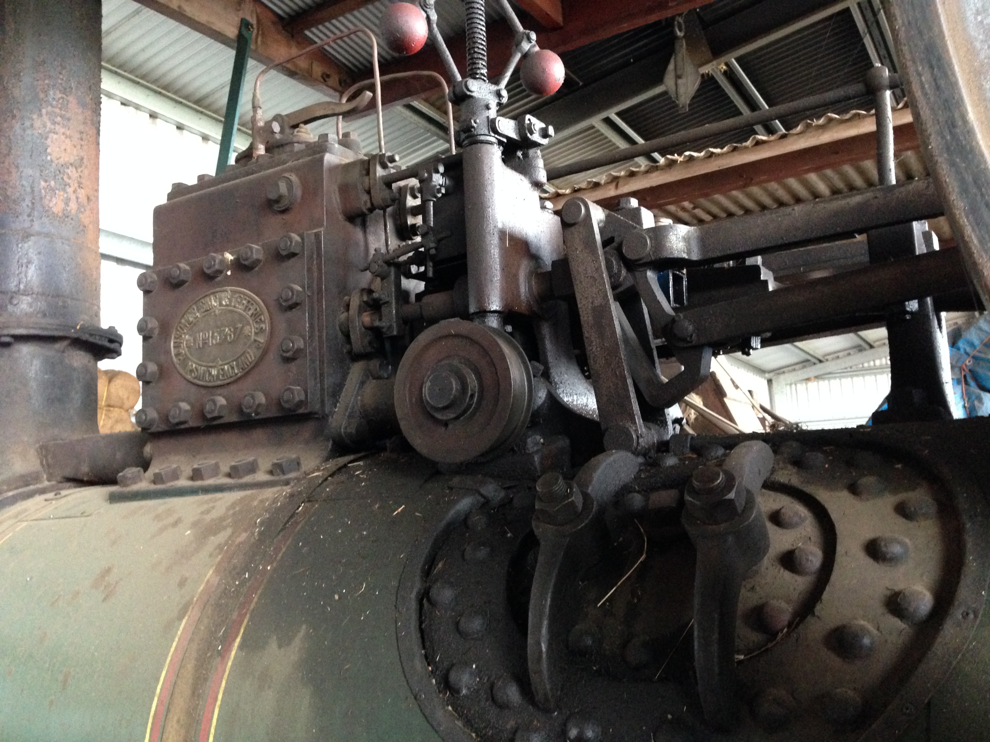
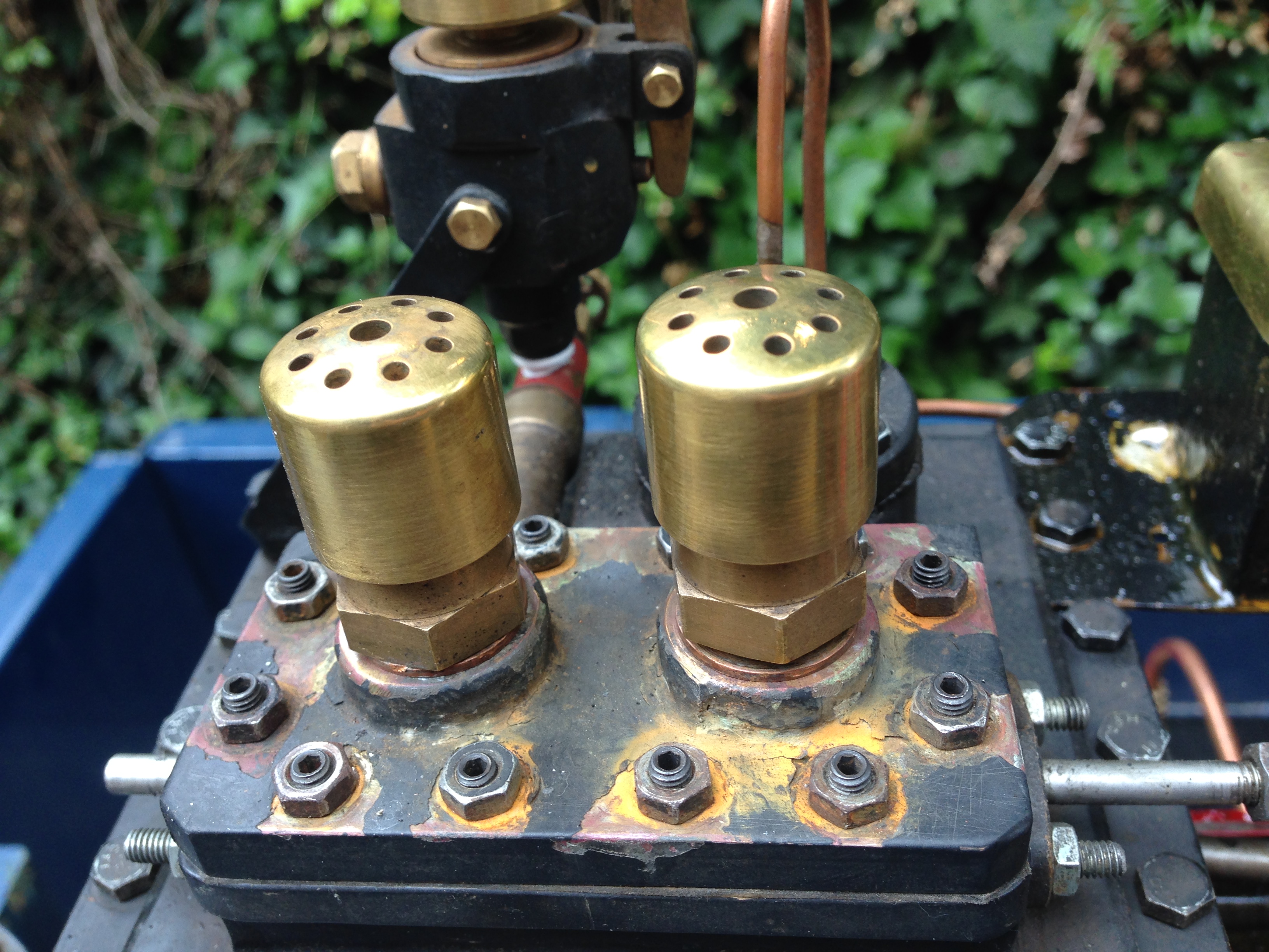
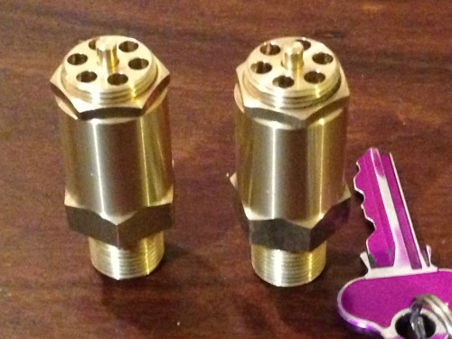
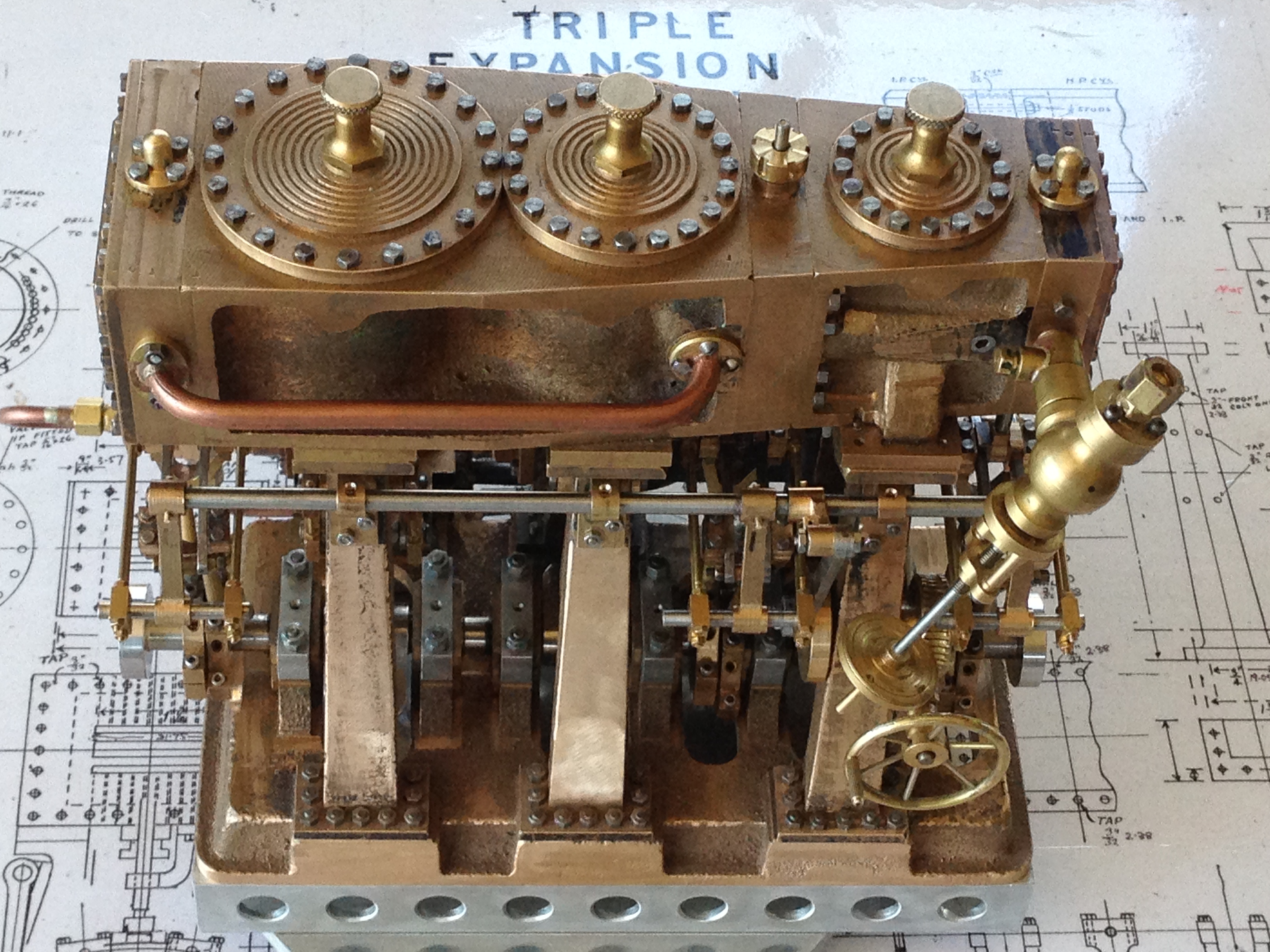
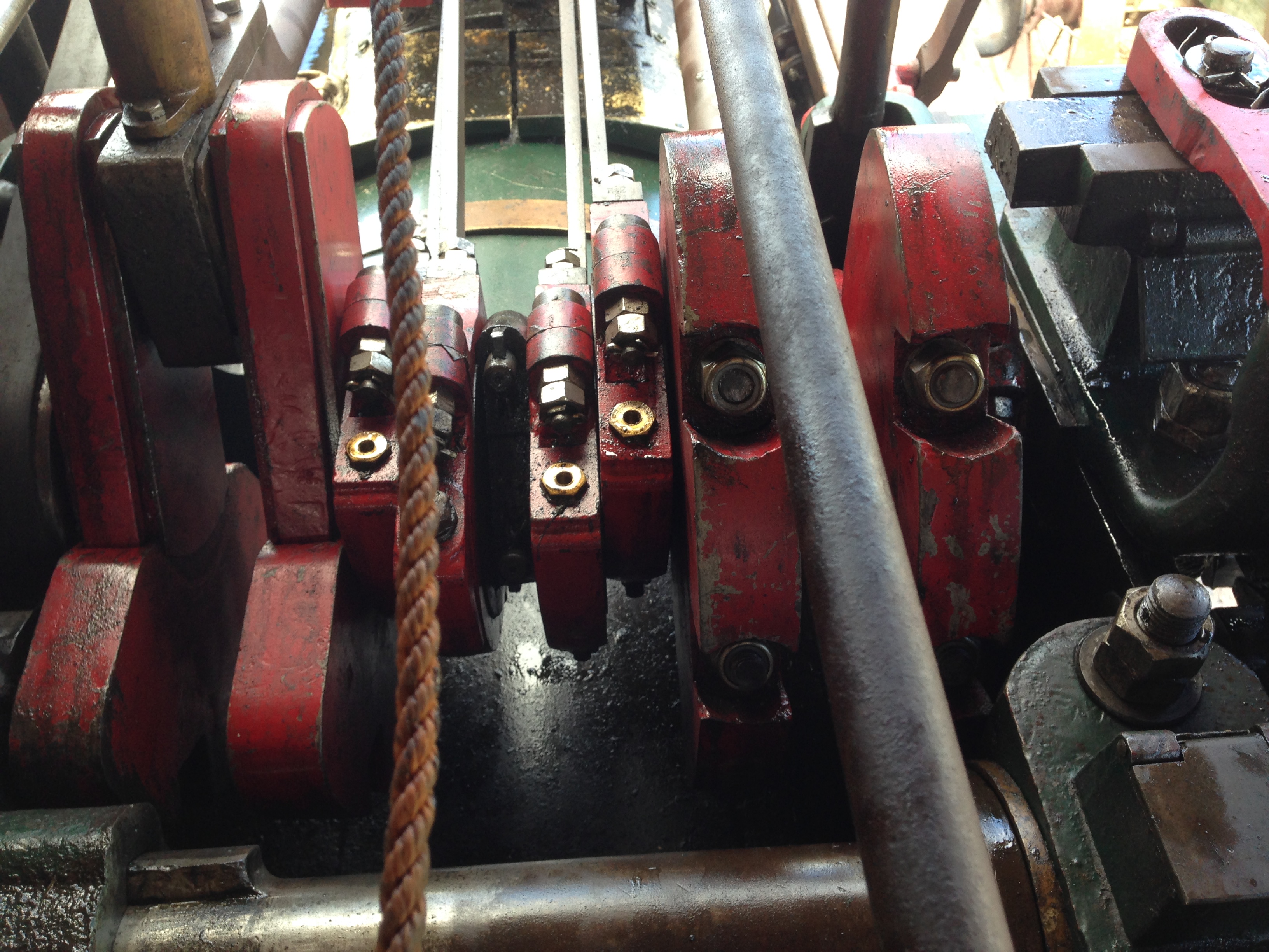
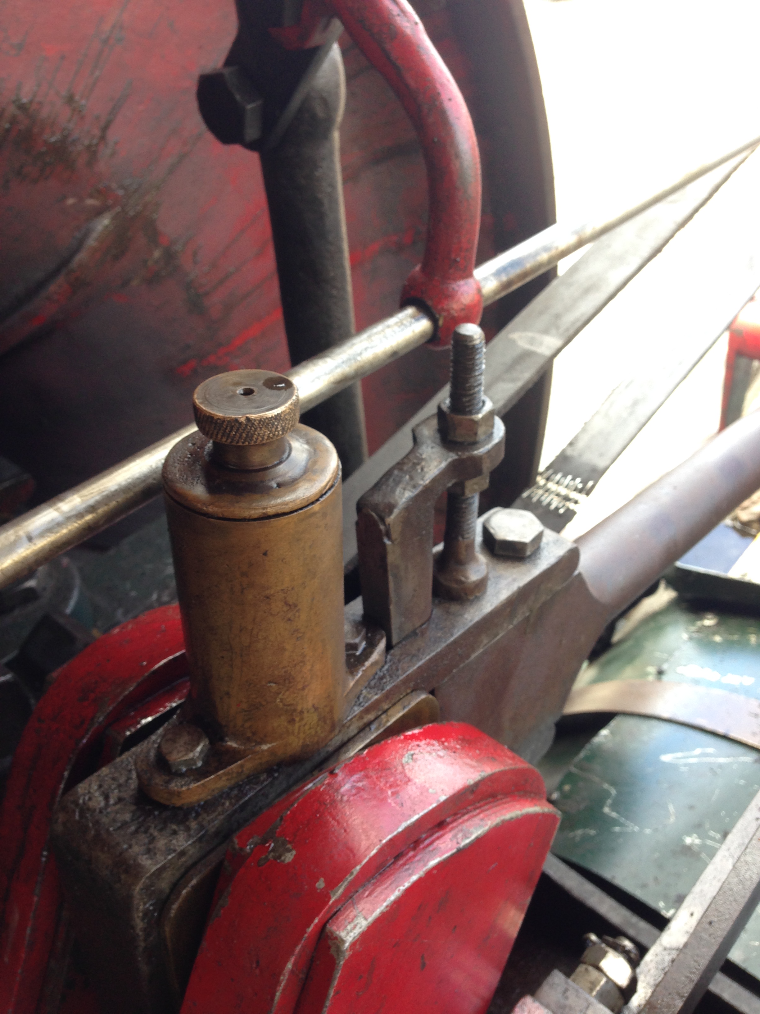
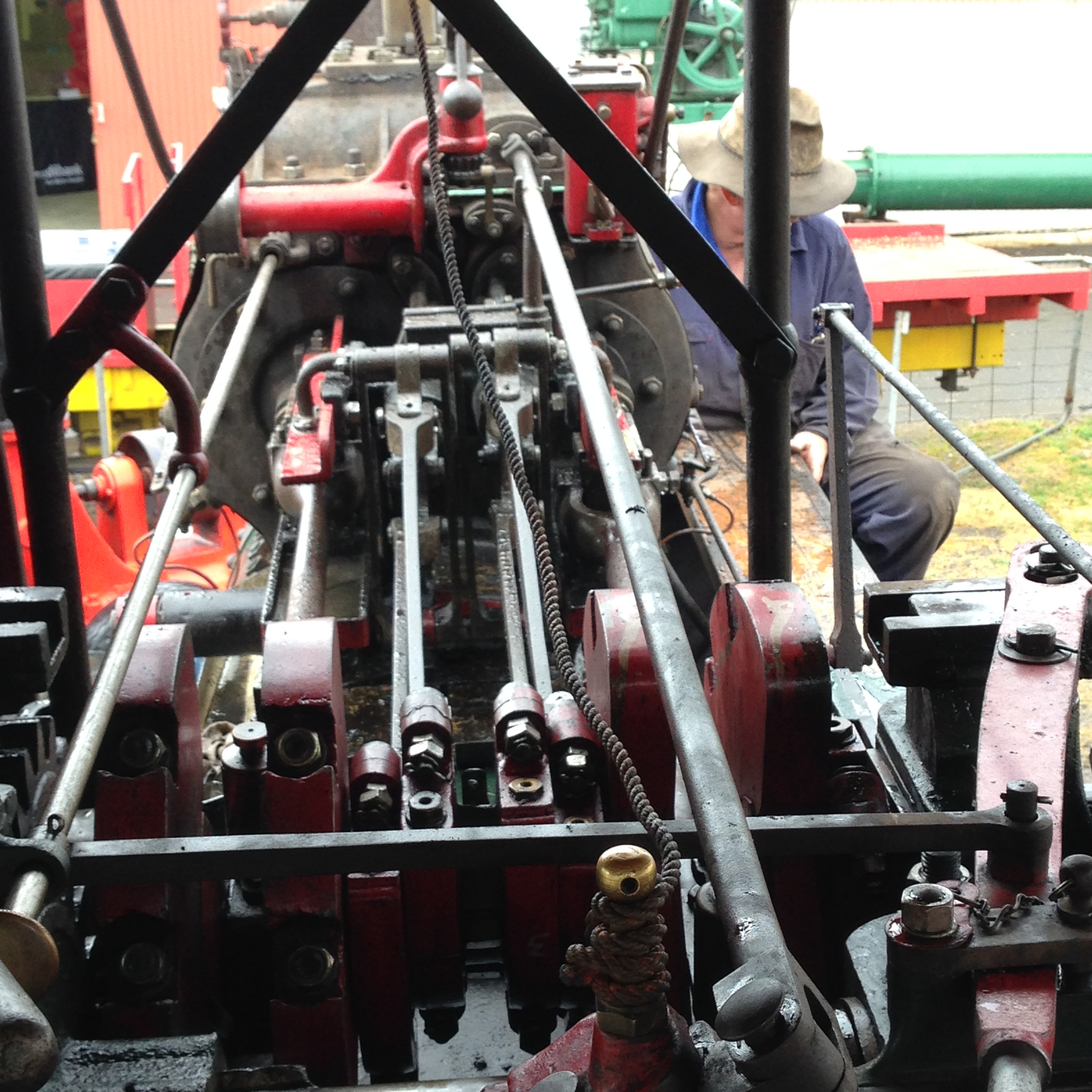
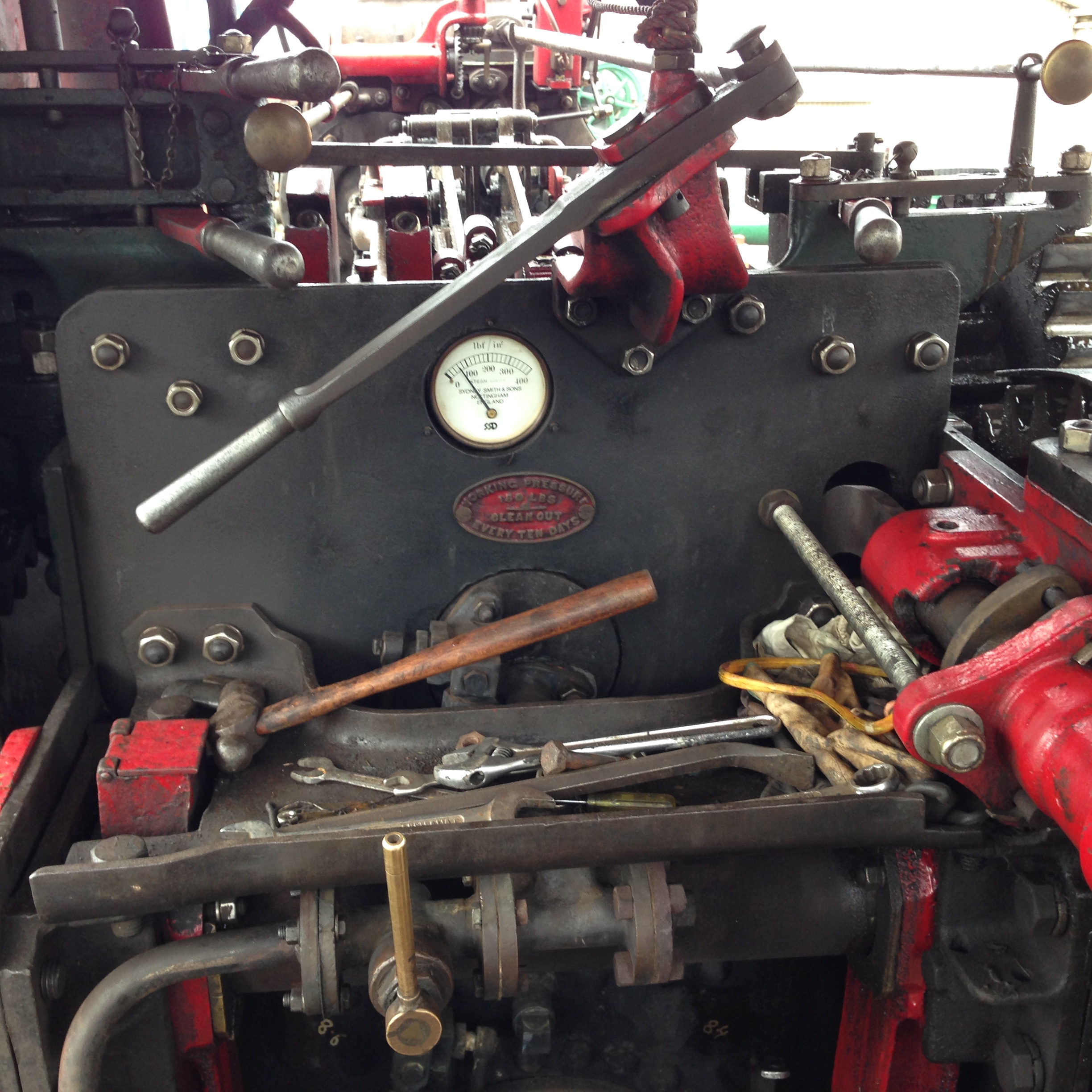
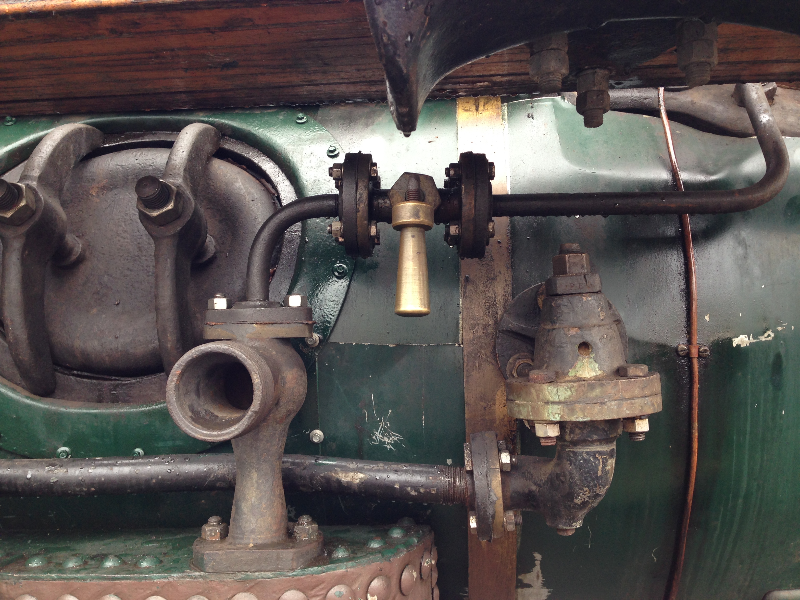
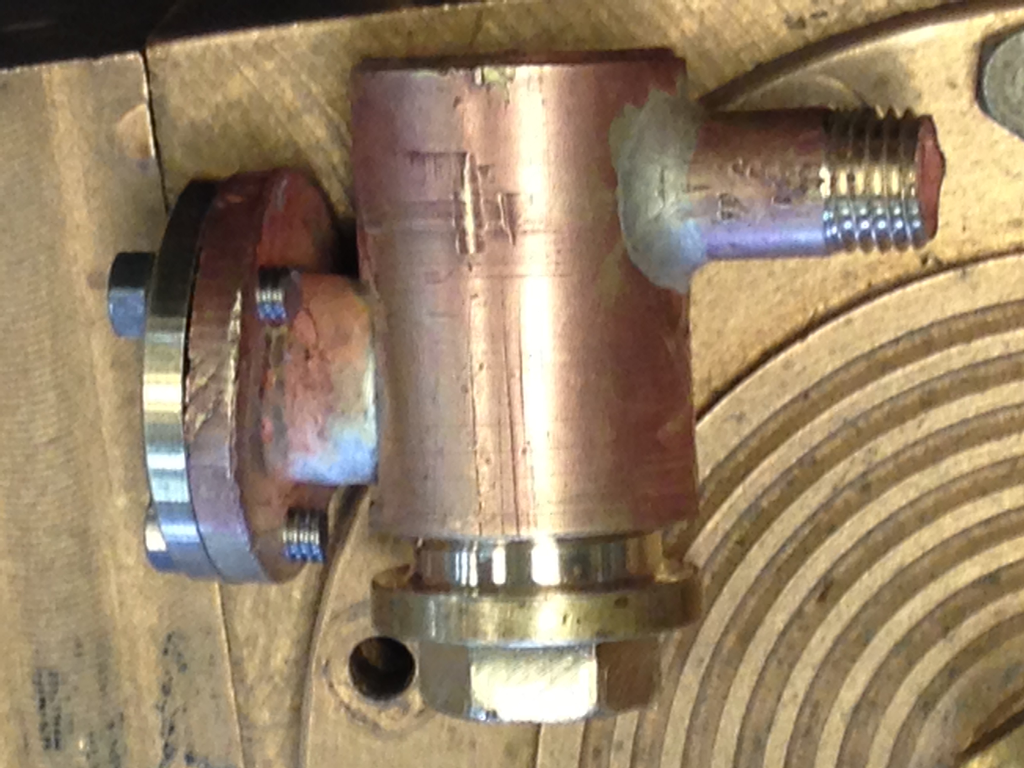
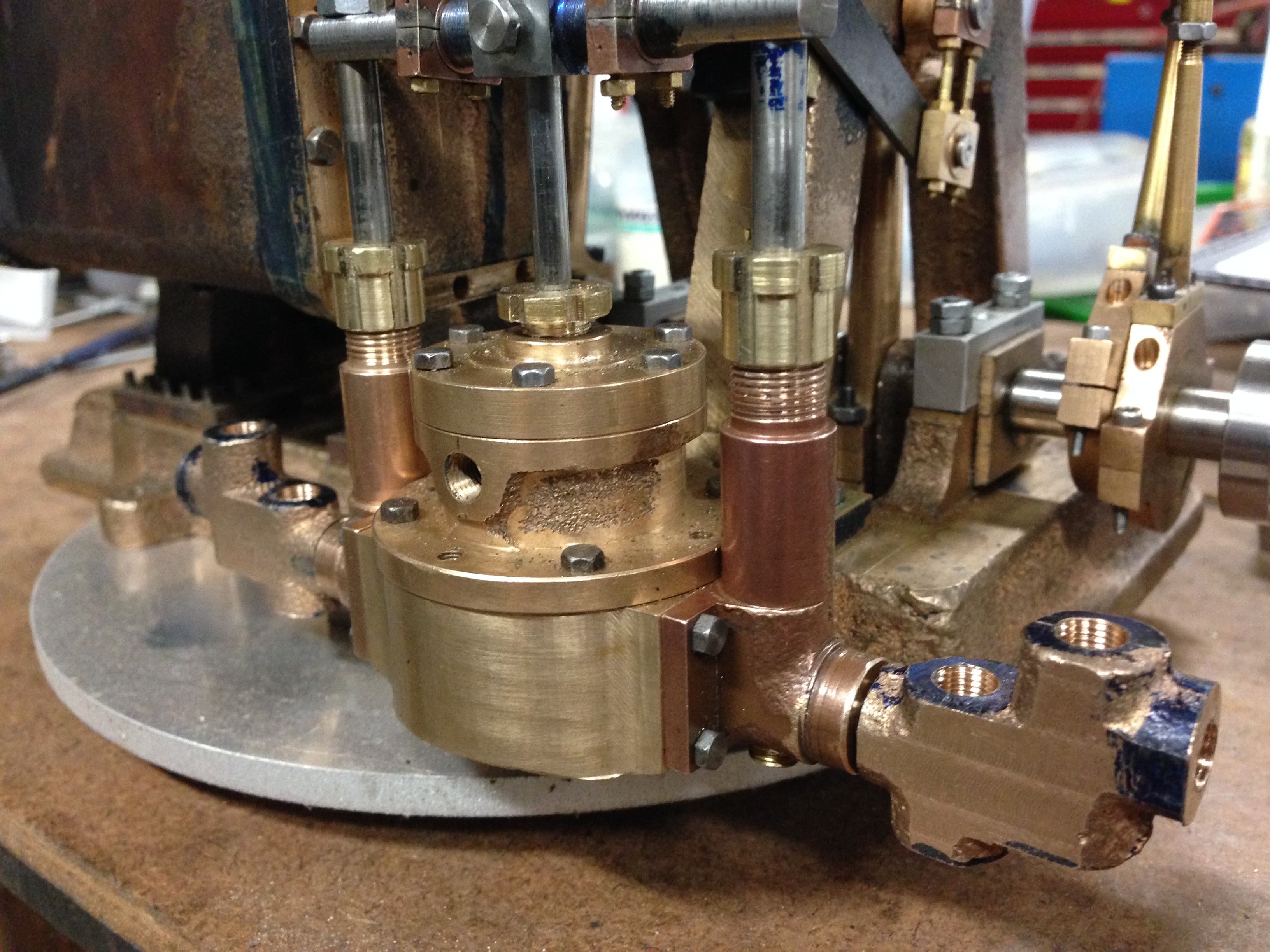
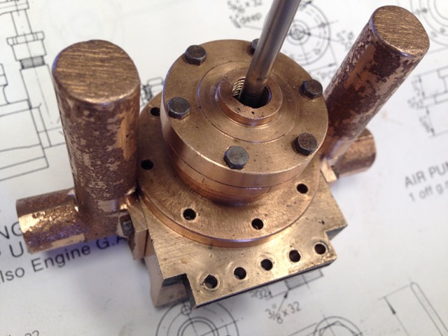
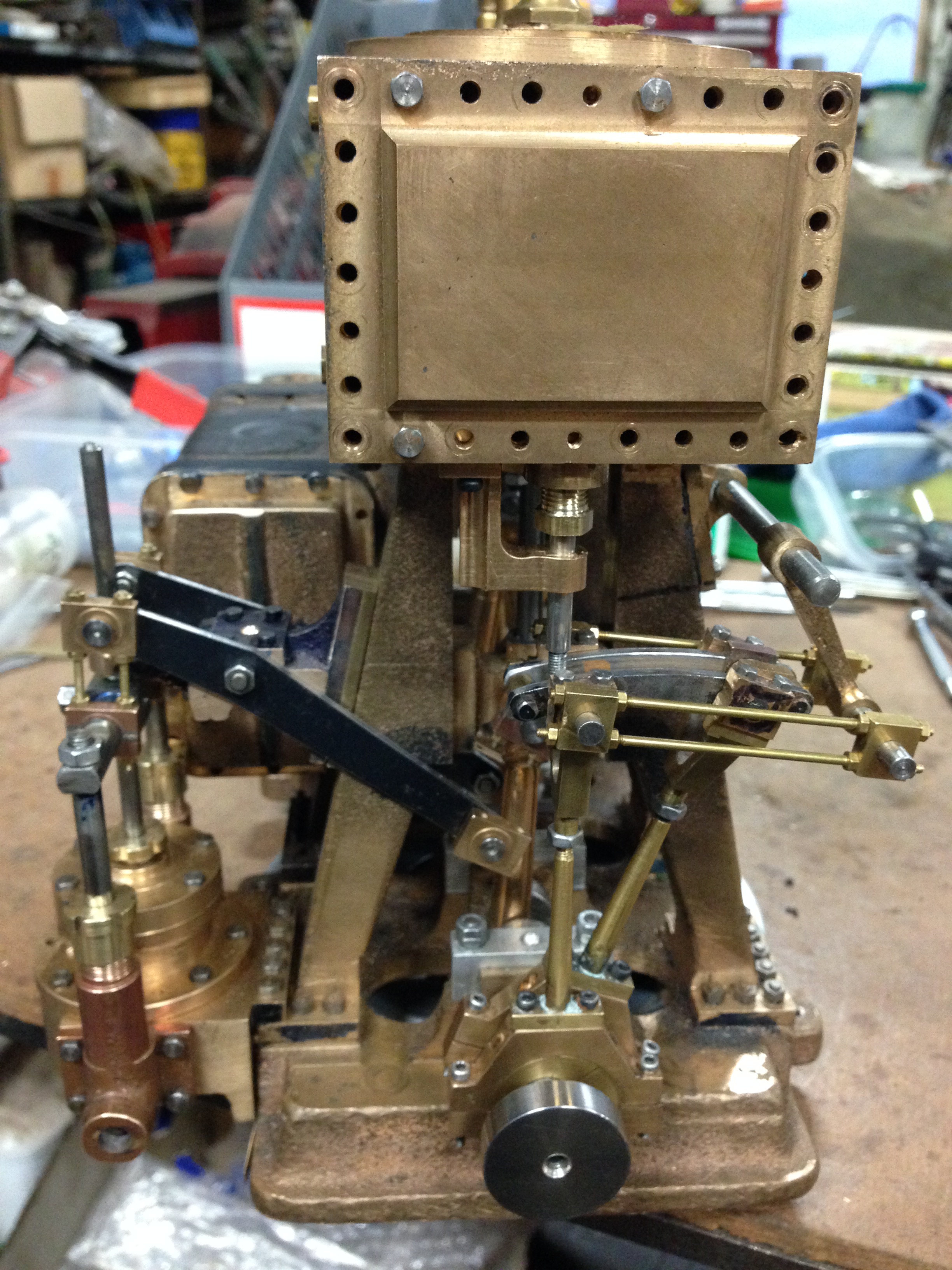
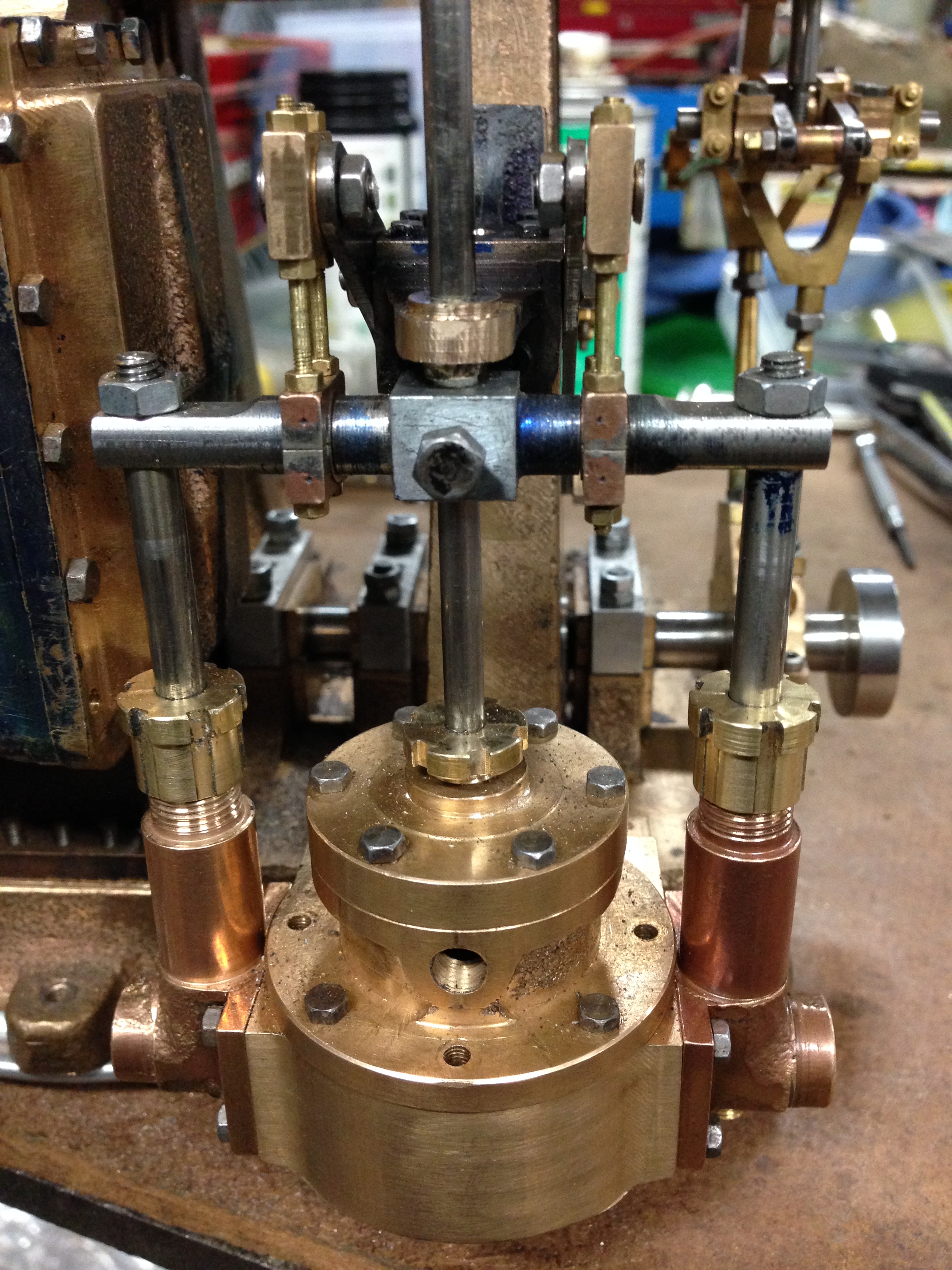
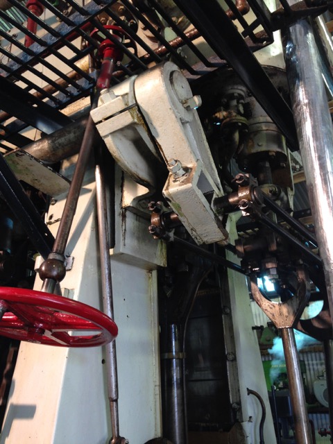
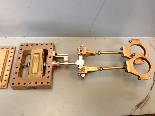
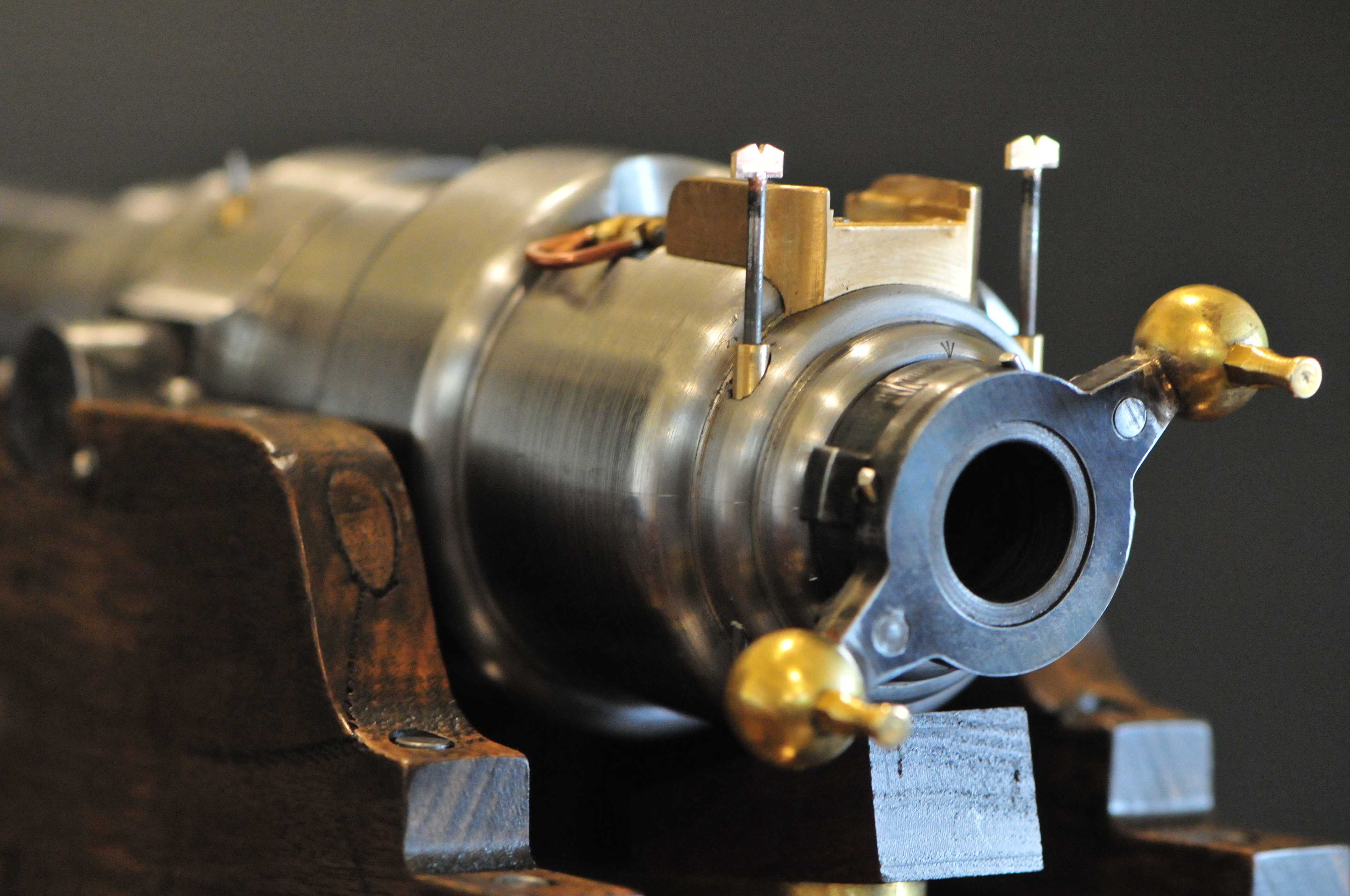
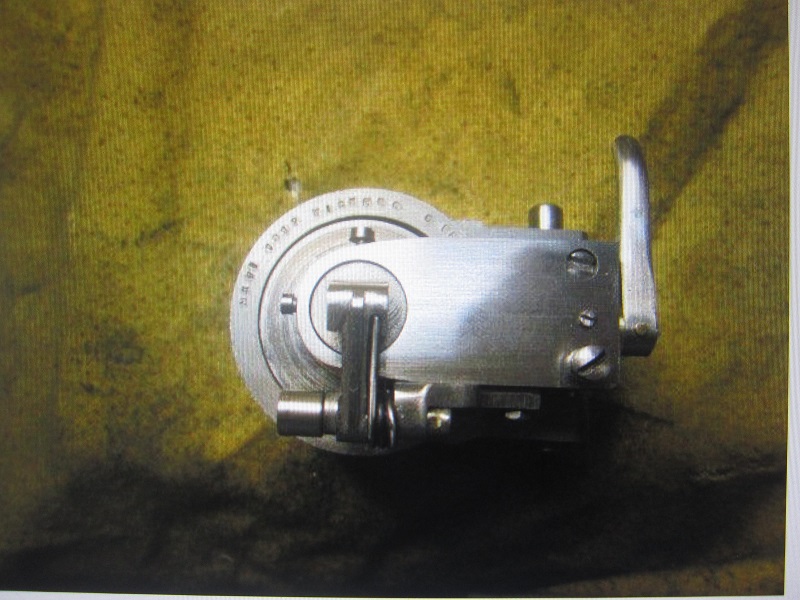
The valves of the beam engine

P1021752.JPG

The beam.  Not the biggest, but it is working on steam.  1840.  Restored 1985.   24 rpm.  690mm bore, 1200mm stroke.  Direct drive to the winding drum.

P1021766.JPG

I do not have enough space for videos of the engine operating, But will put them on YouTube later.

I have not touched on the topic of women and children working in the mines.  It happened until well into the 20th century.  Look up “Bal maidens” for information on women in the mining industry.  They were a strong lot.

Another highly recommended place to visit.
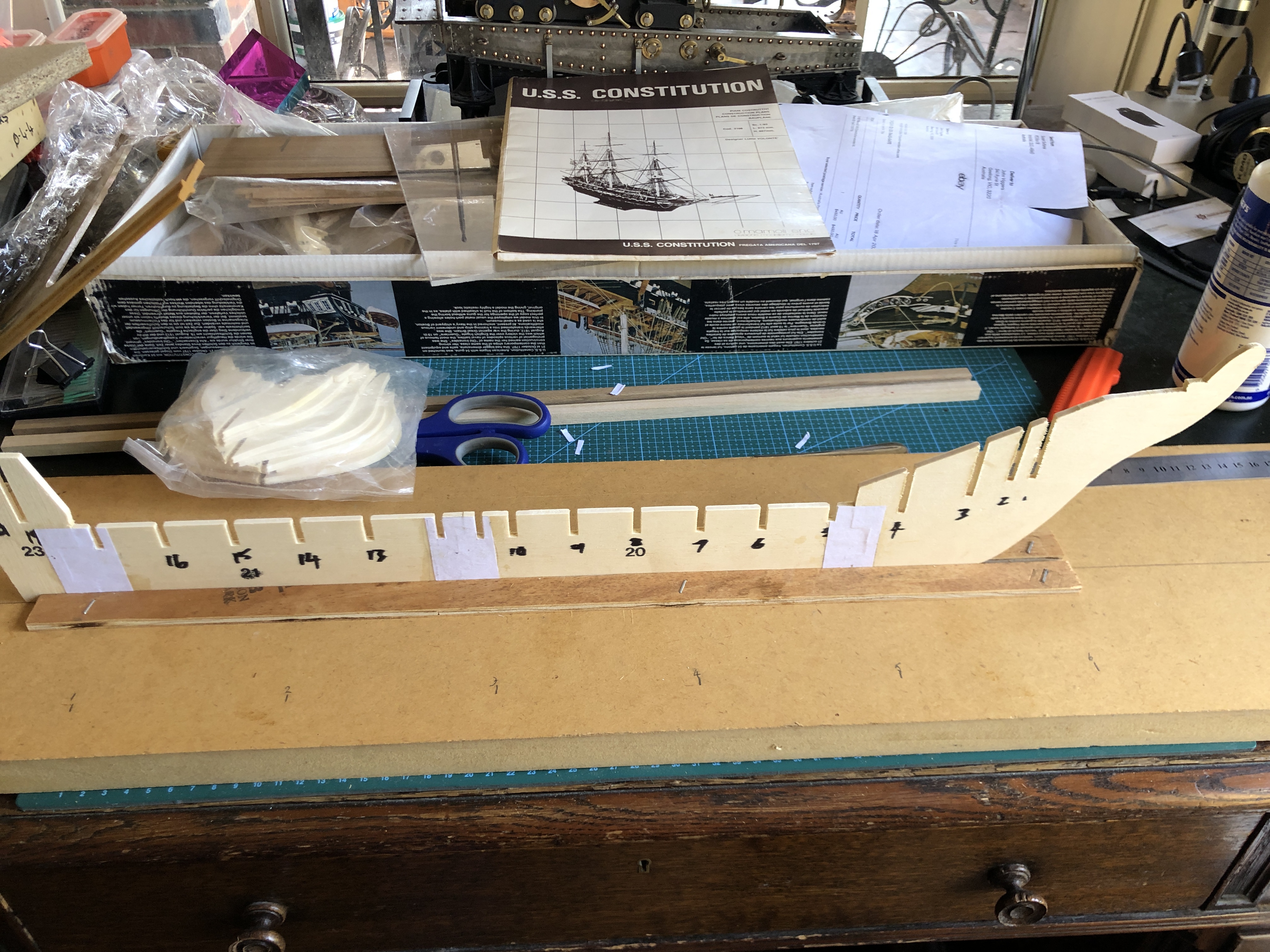
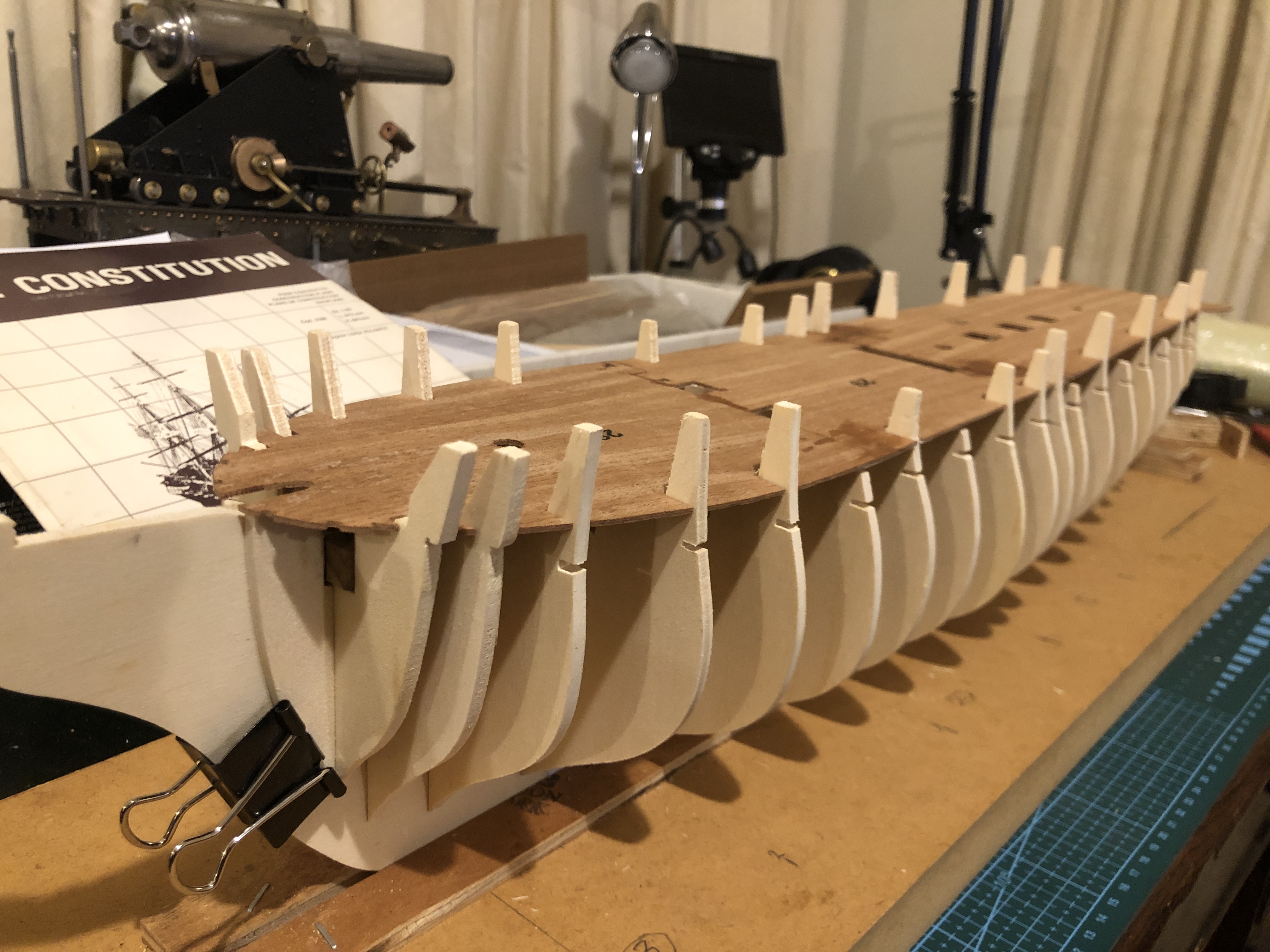
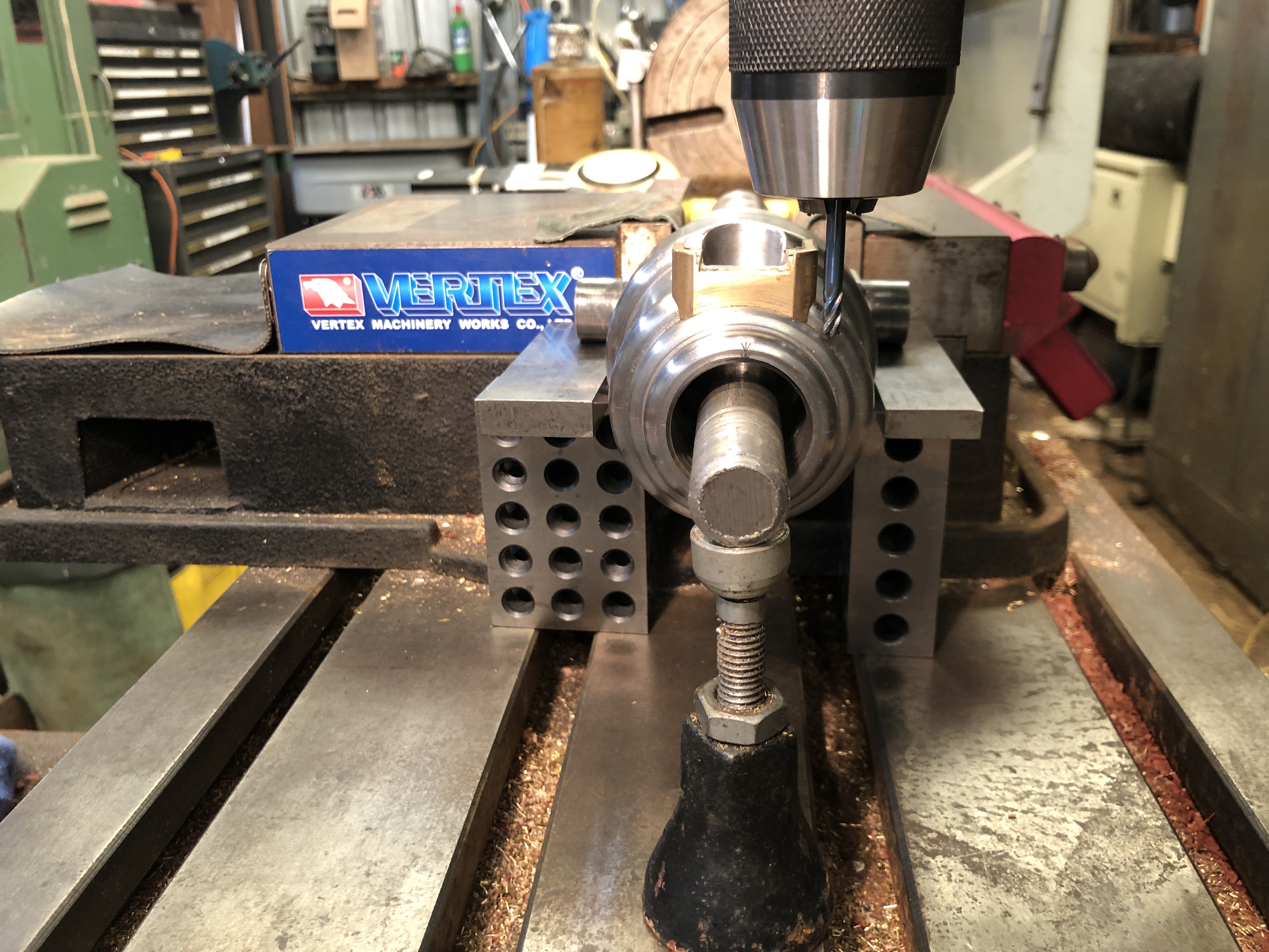
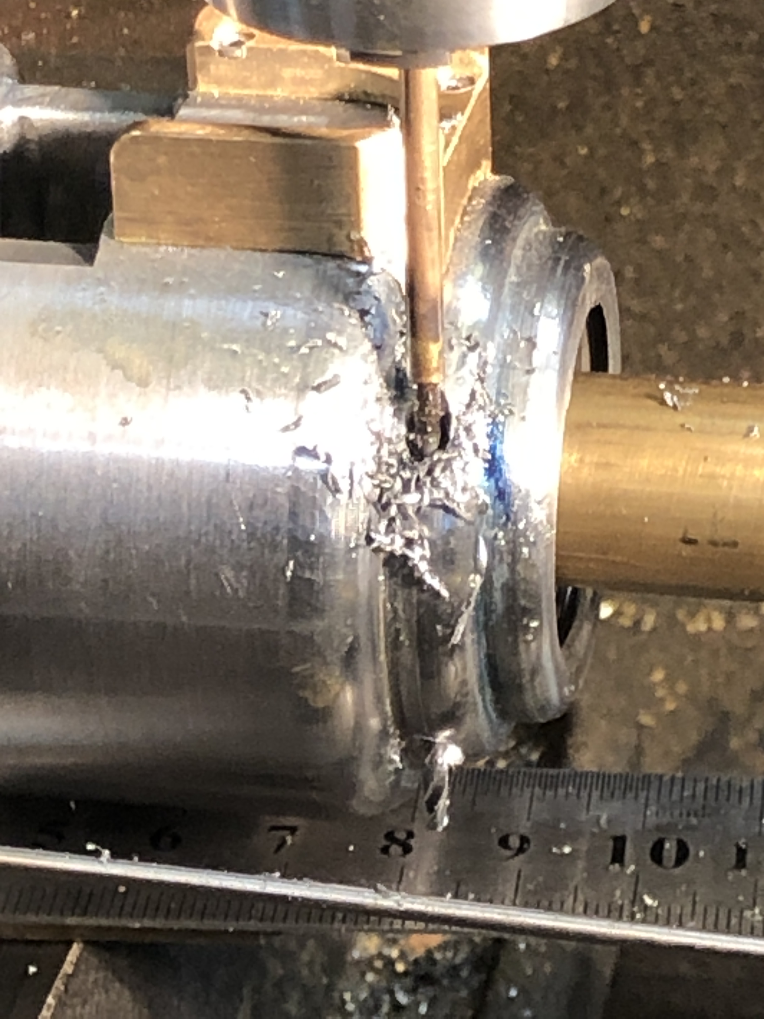
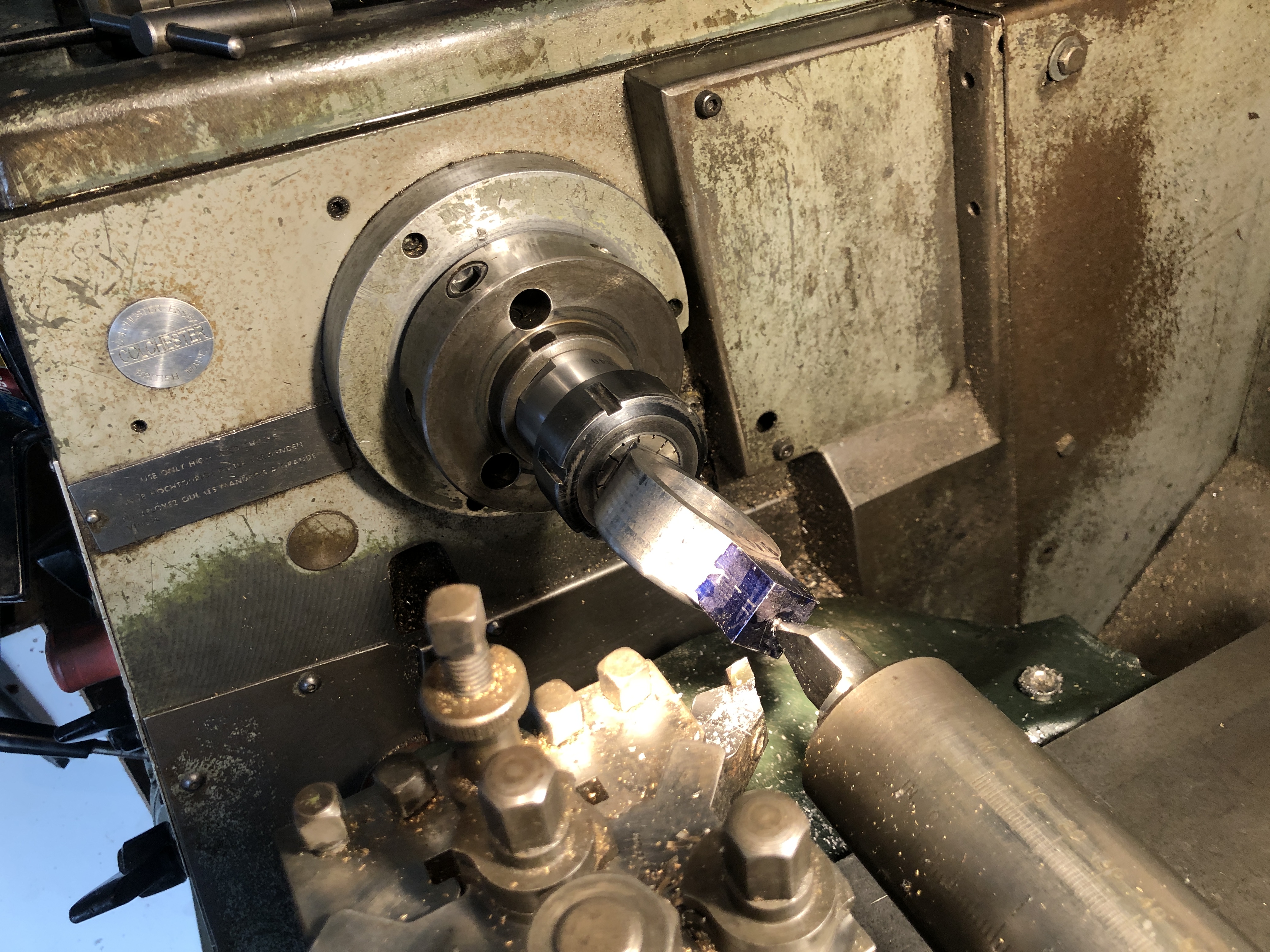
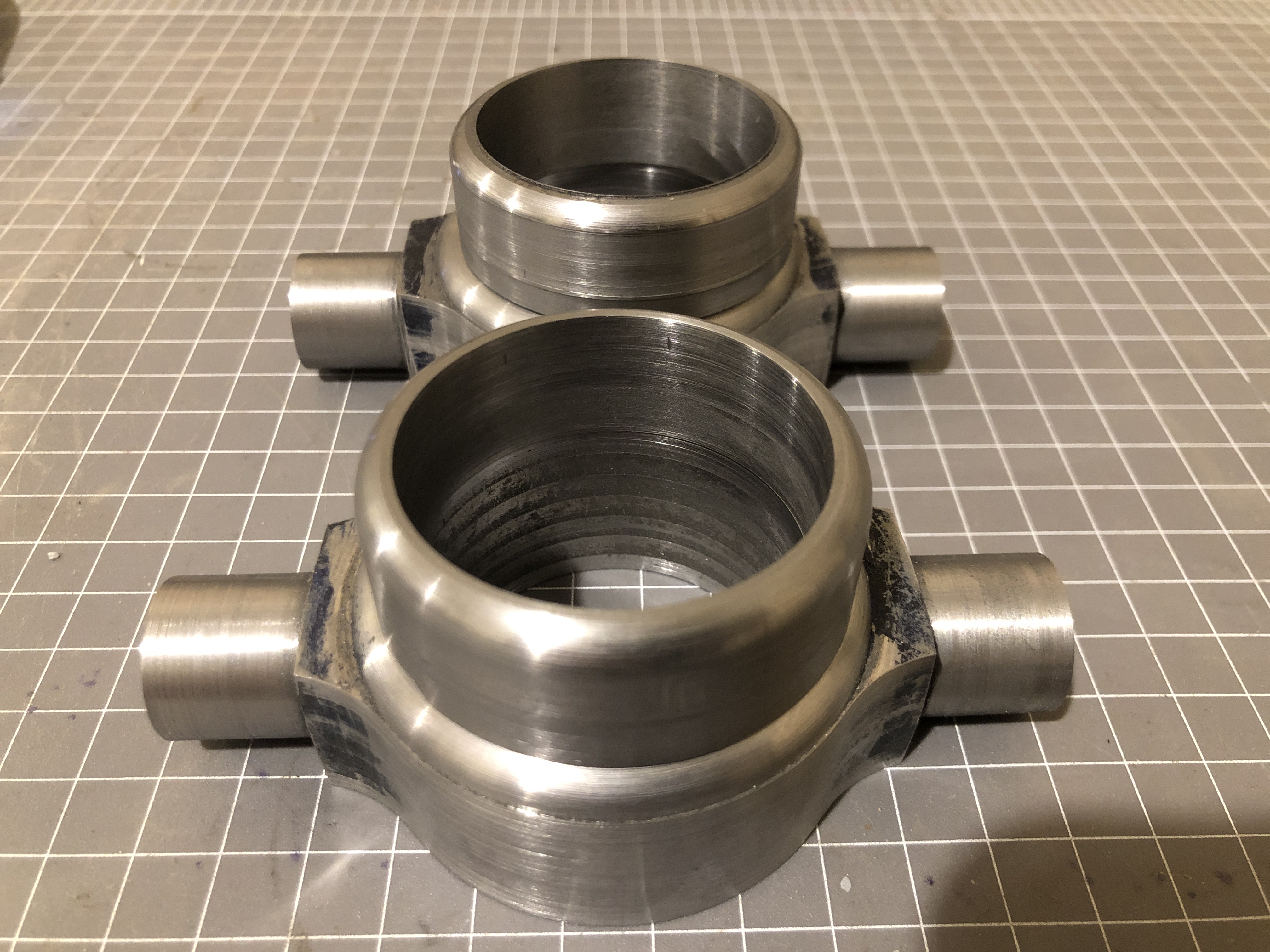
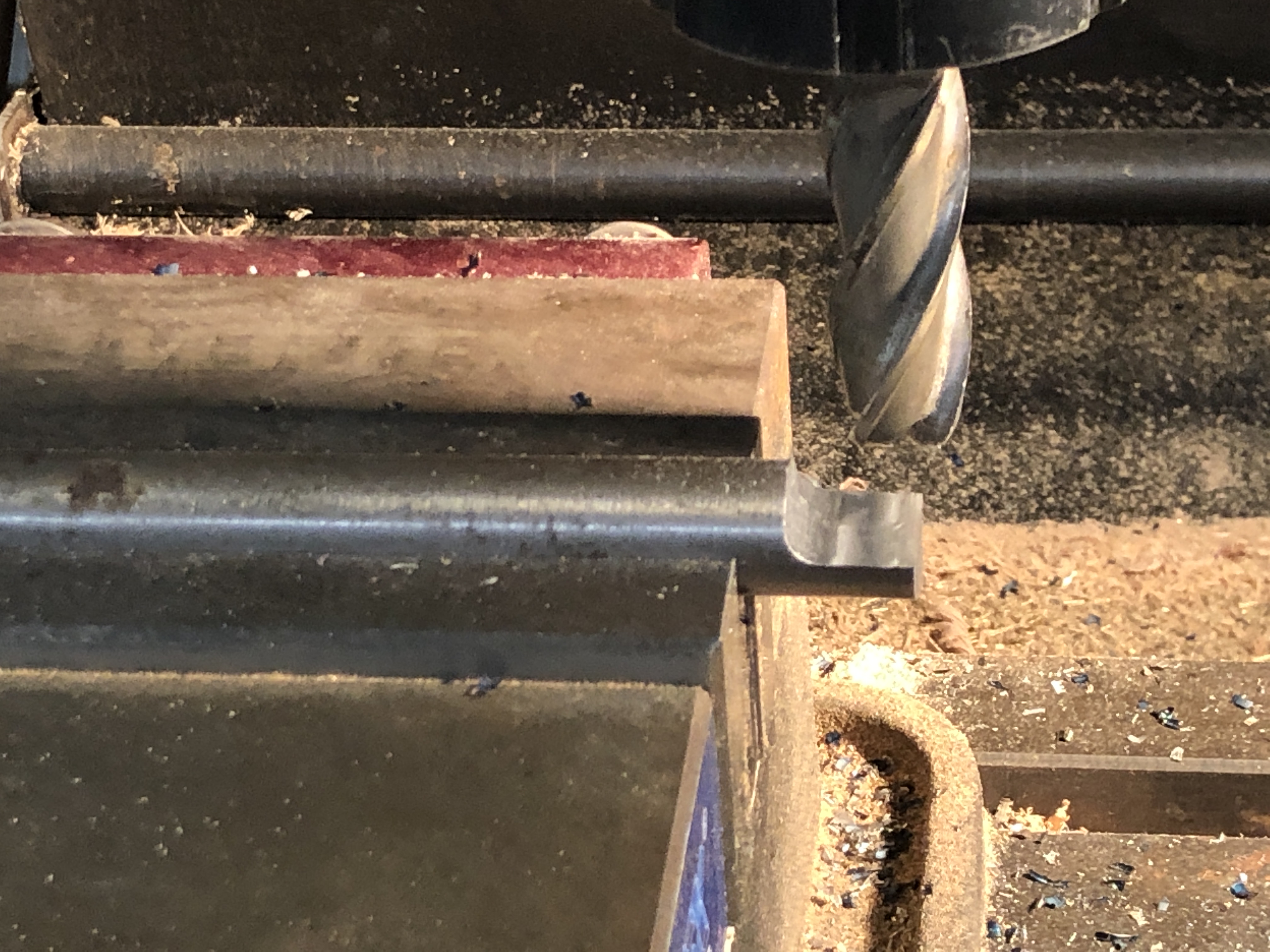
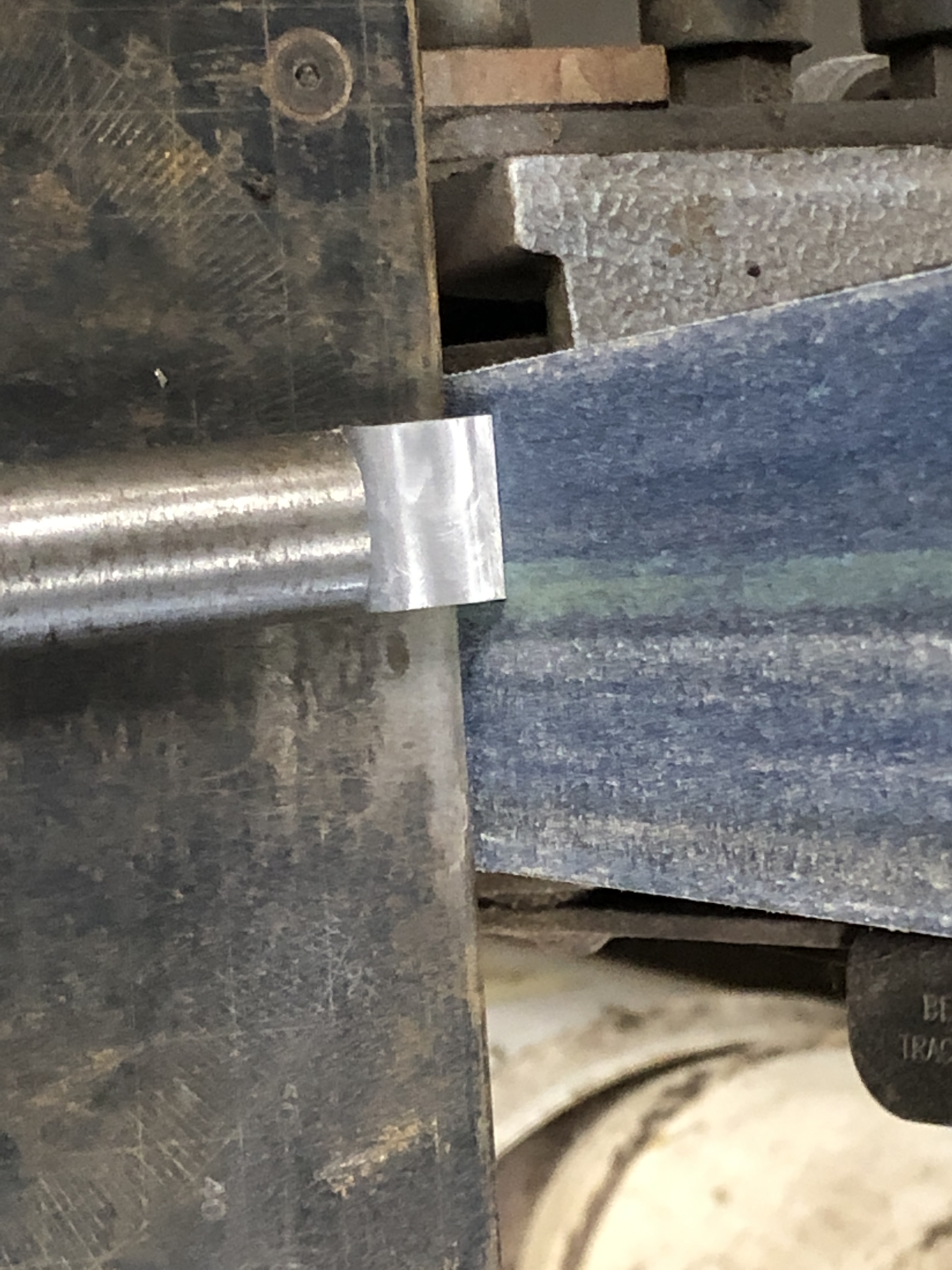
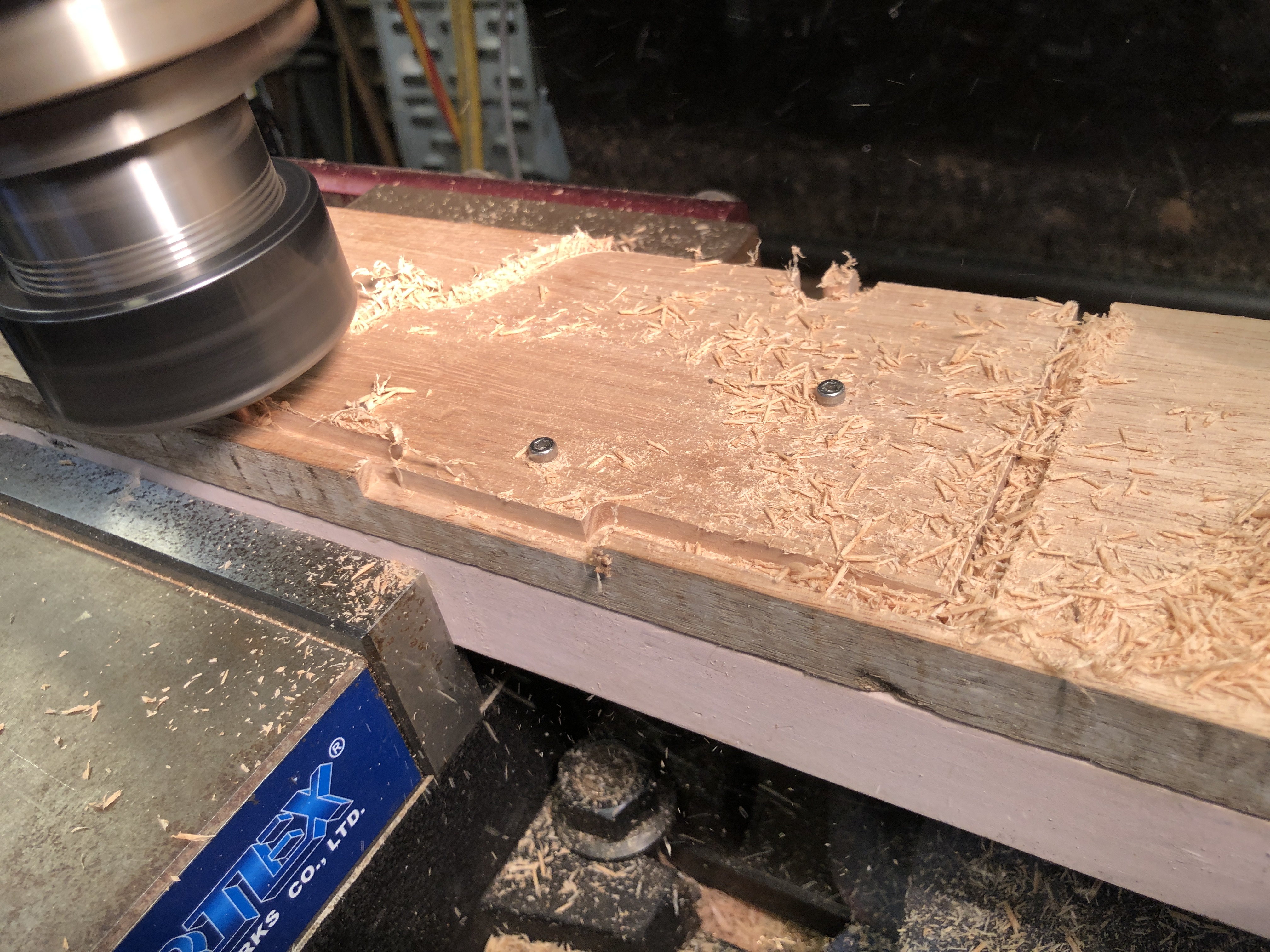
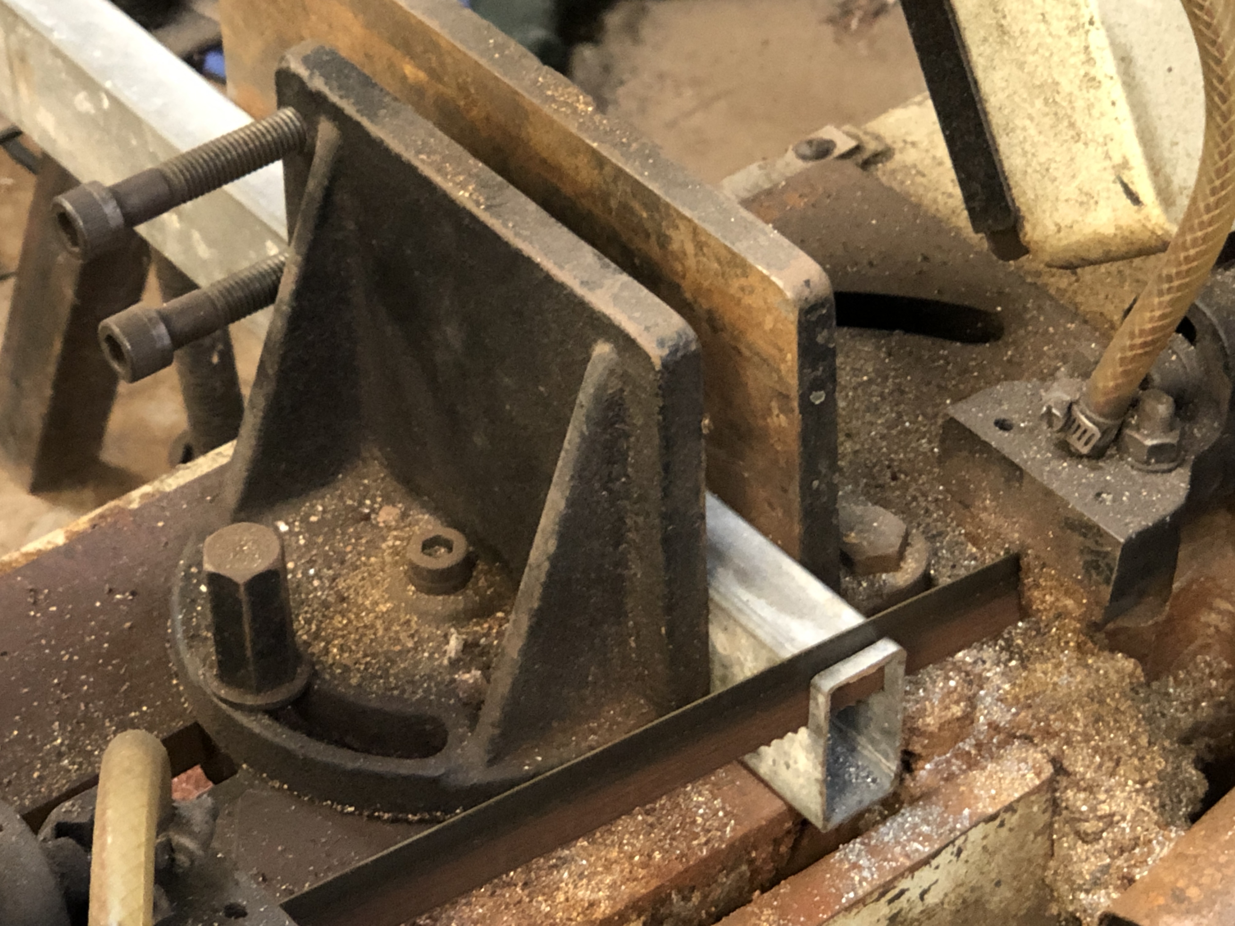
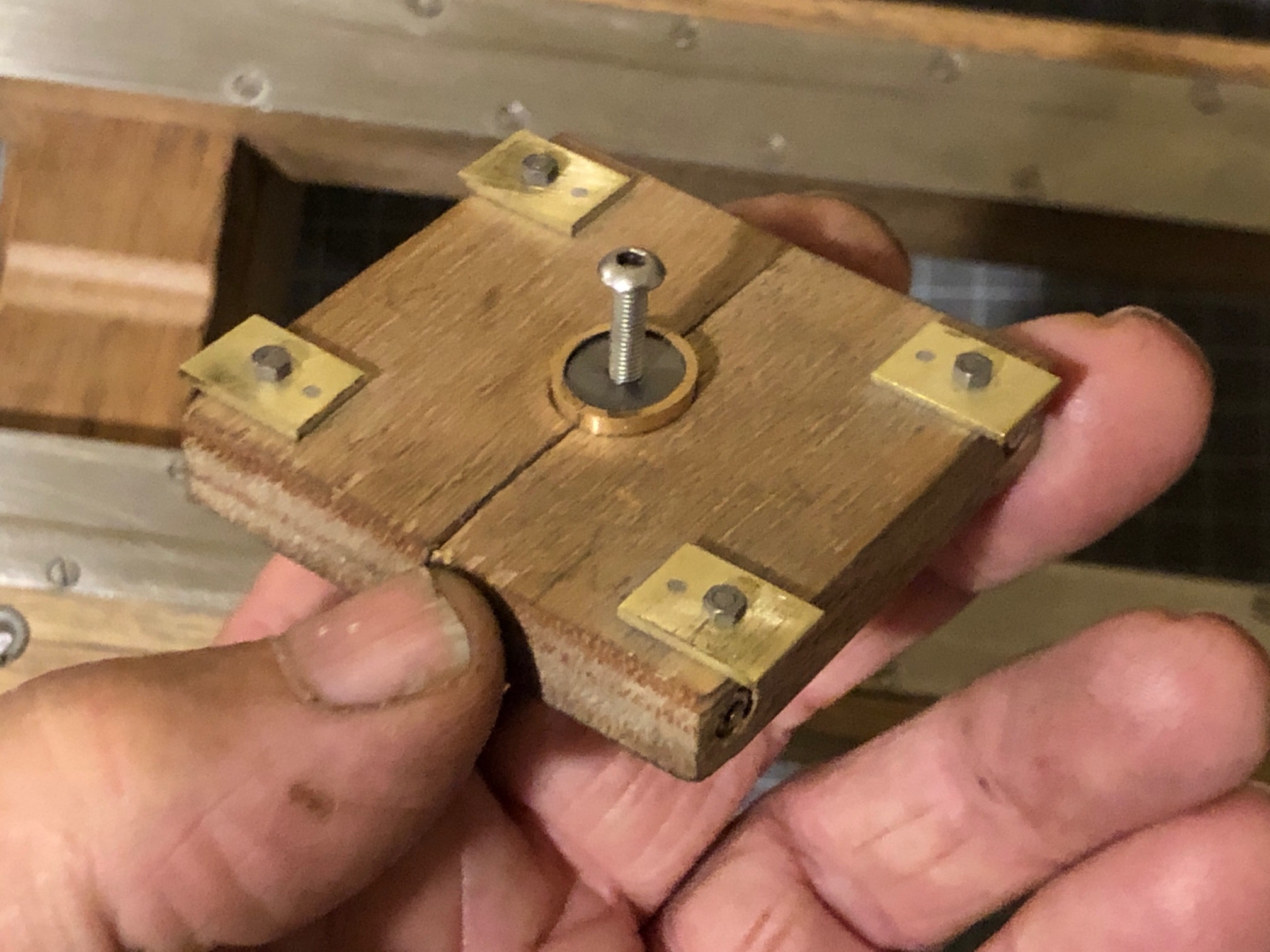
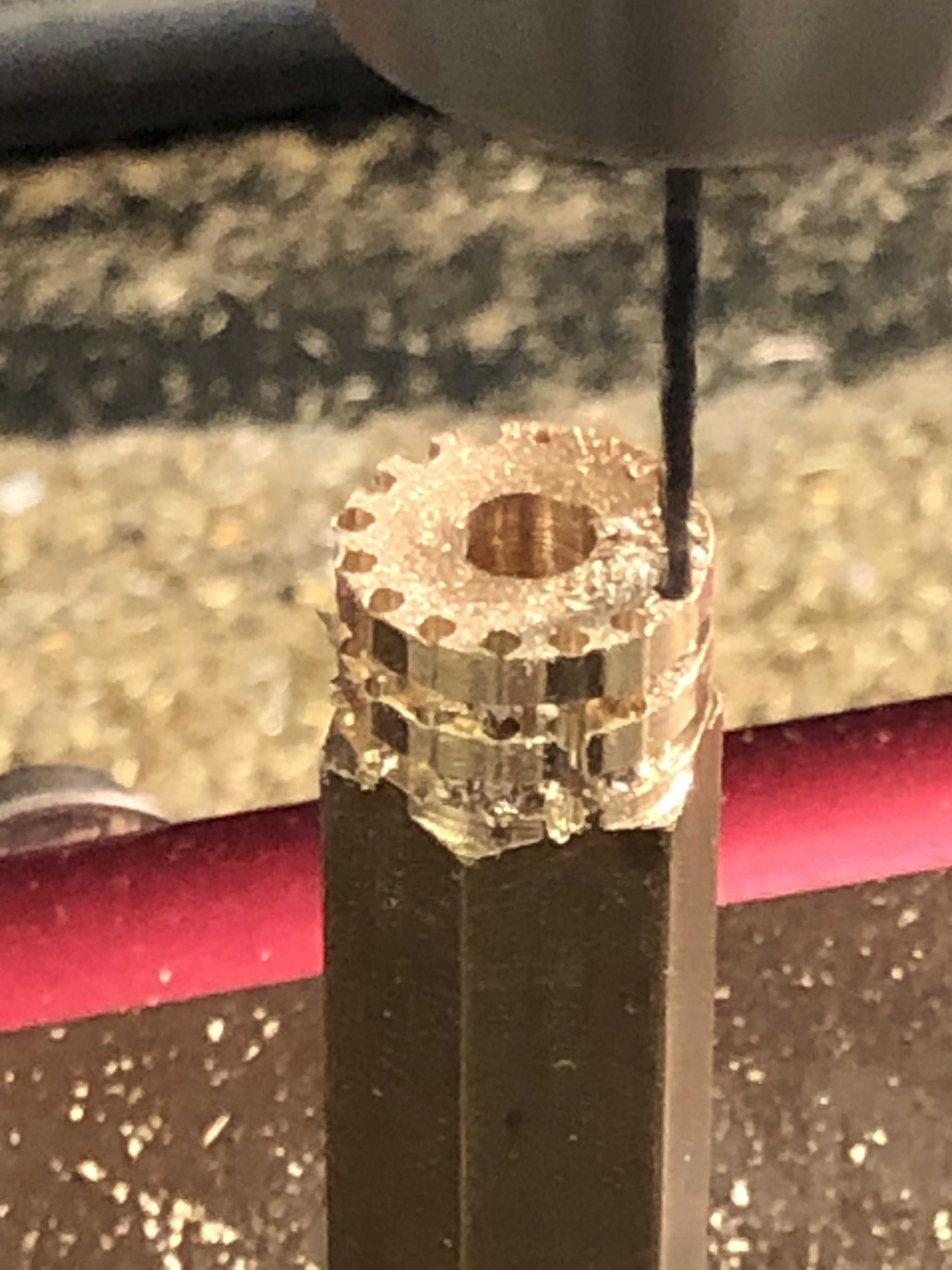
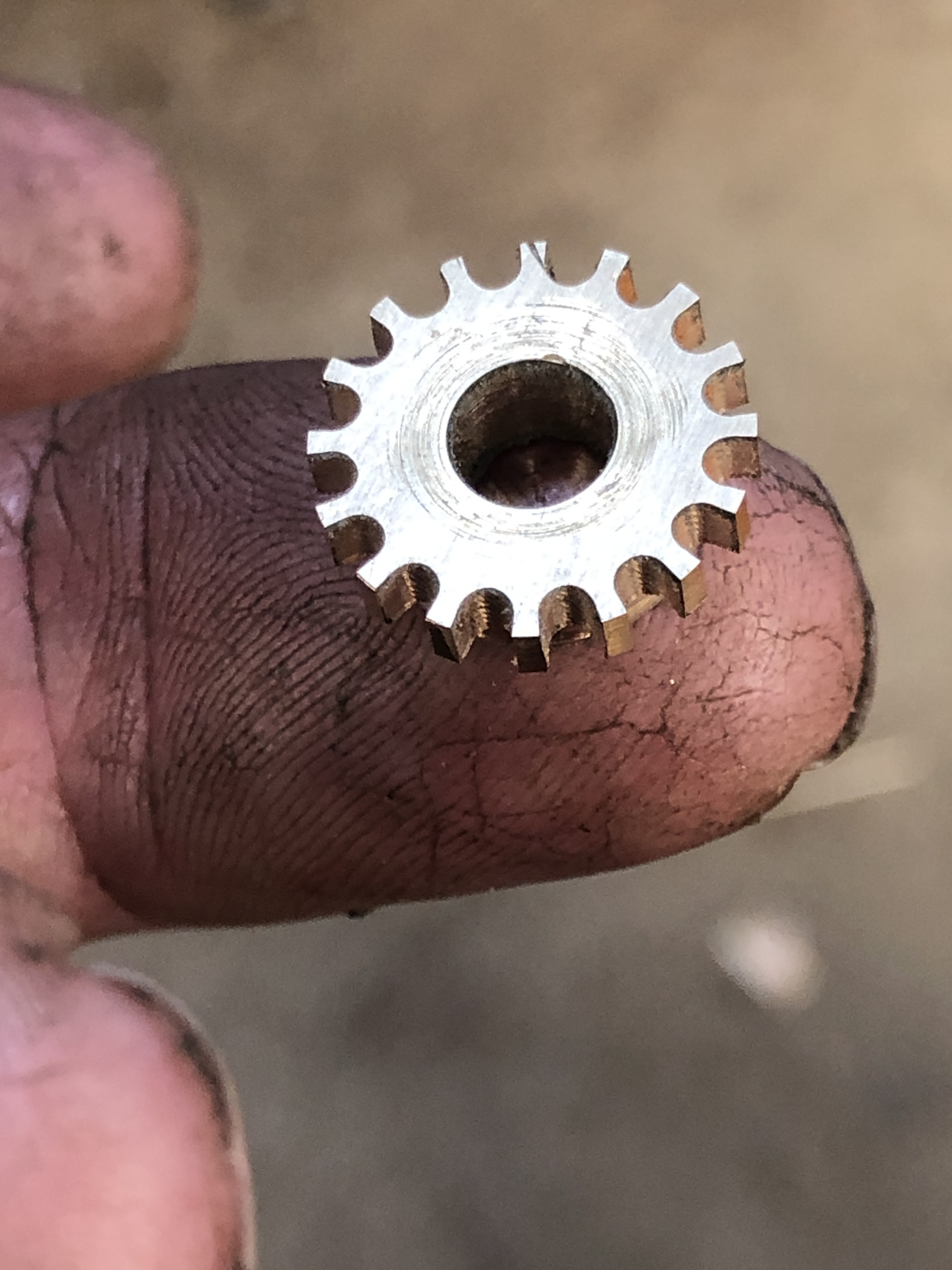
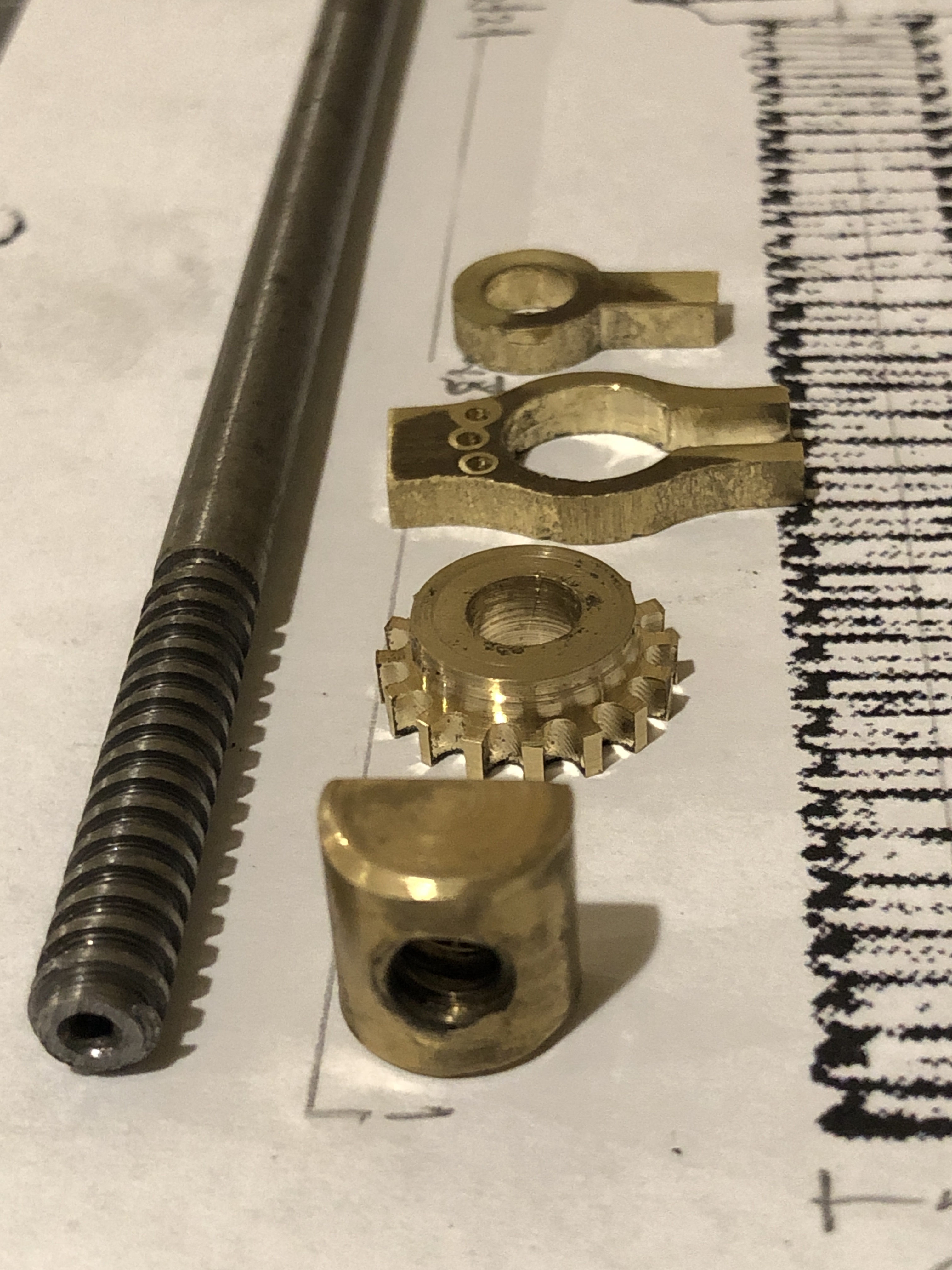
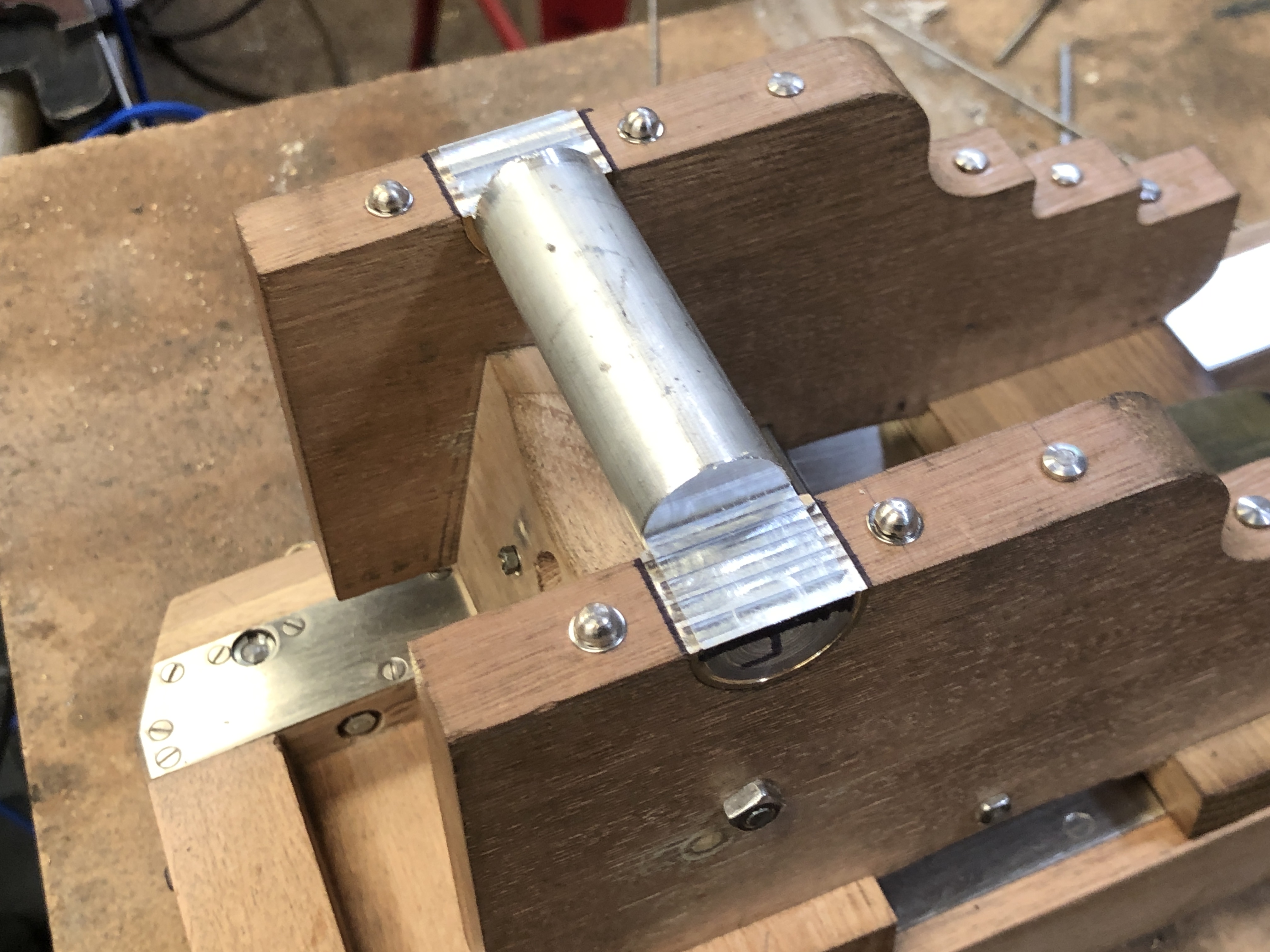
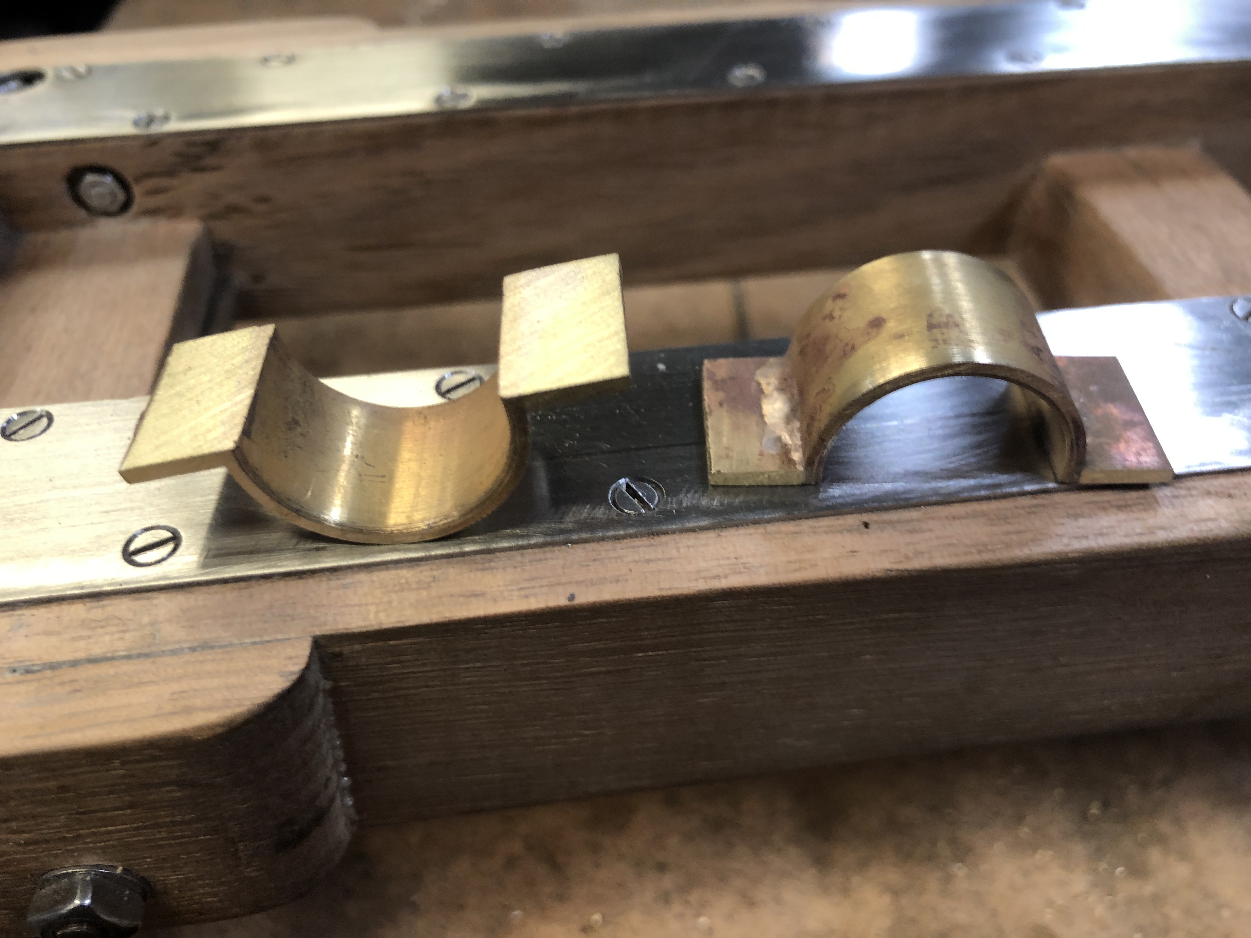
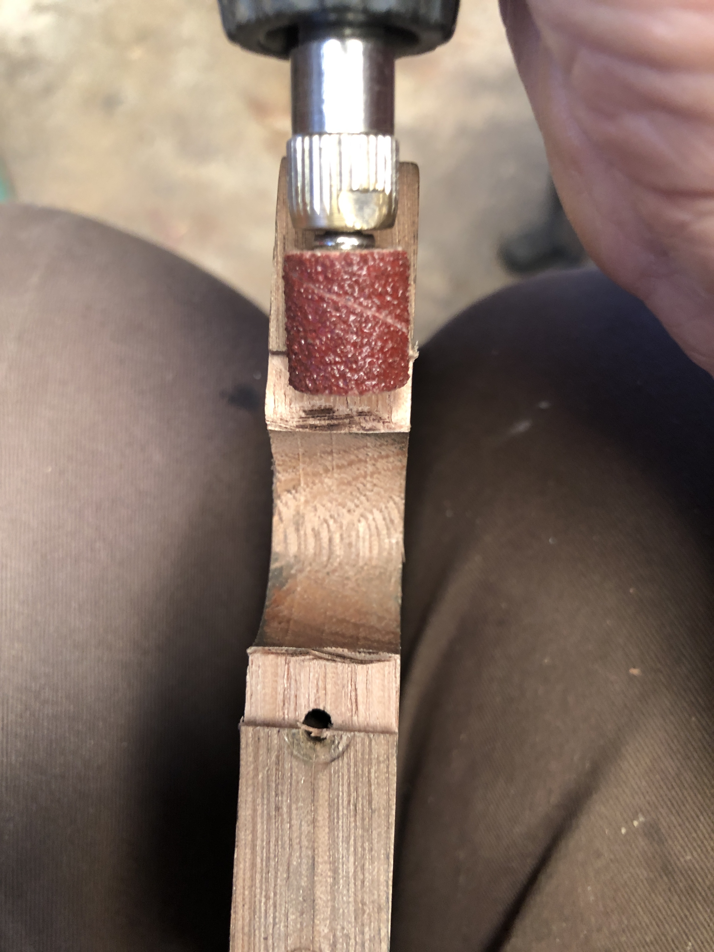
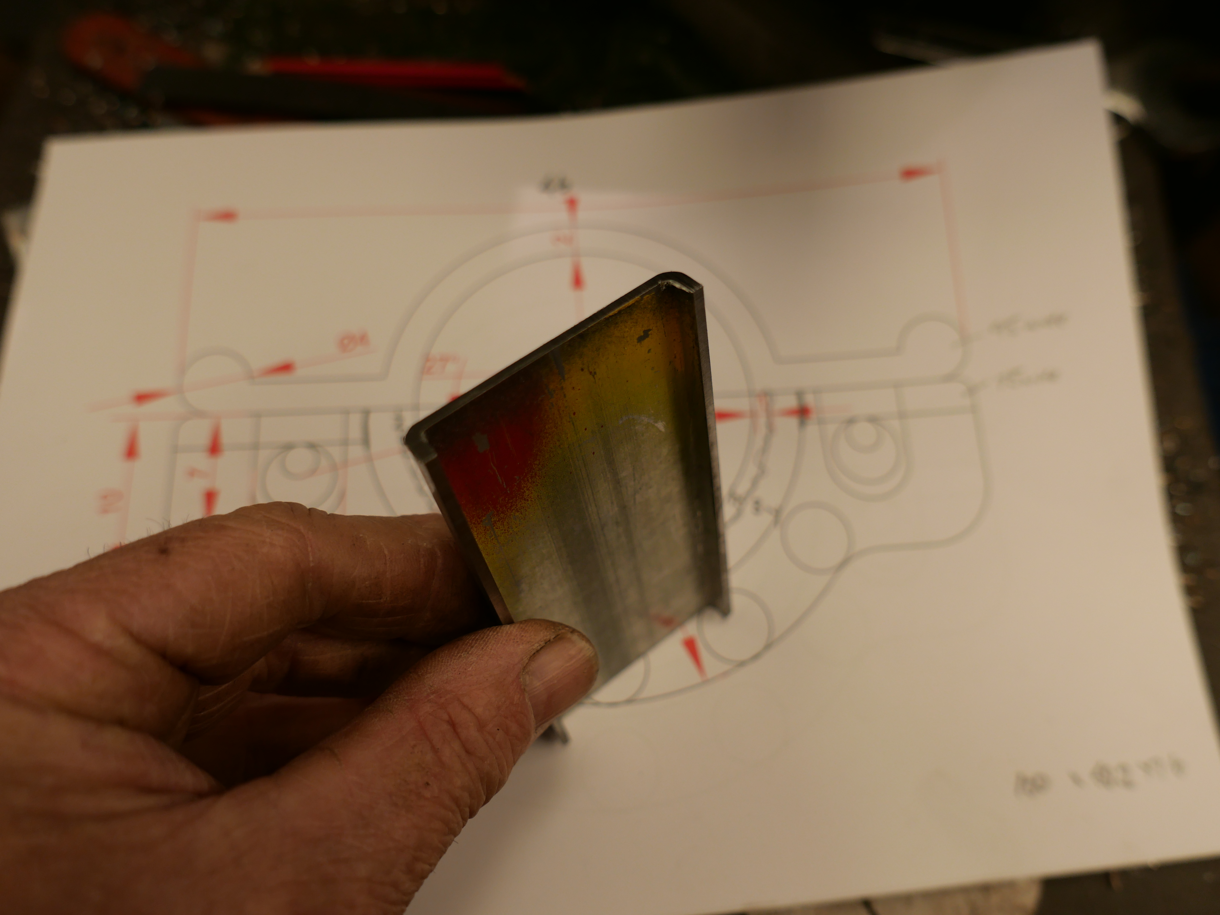
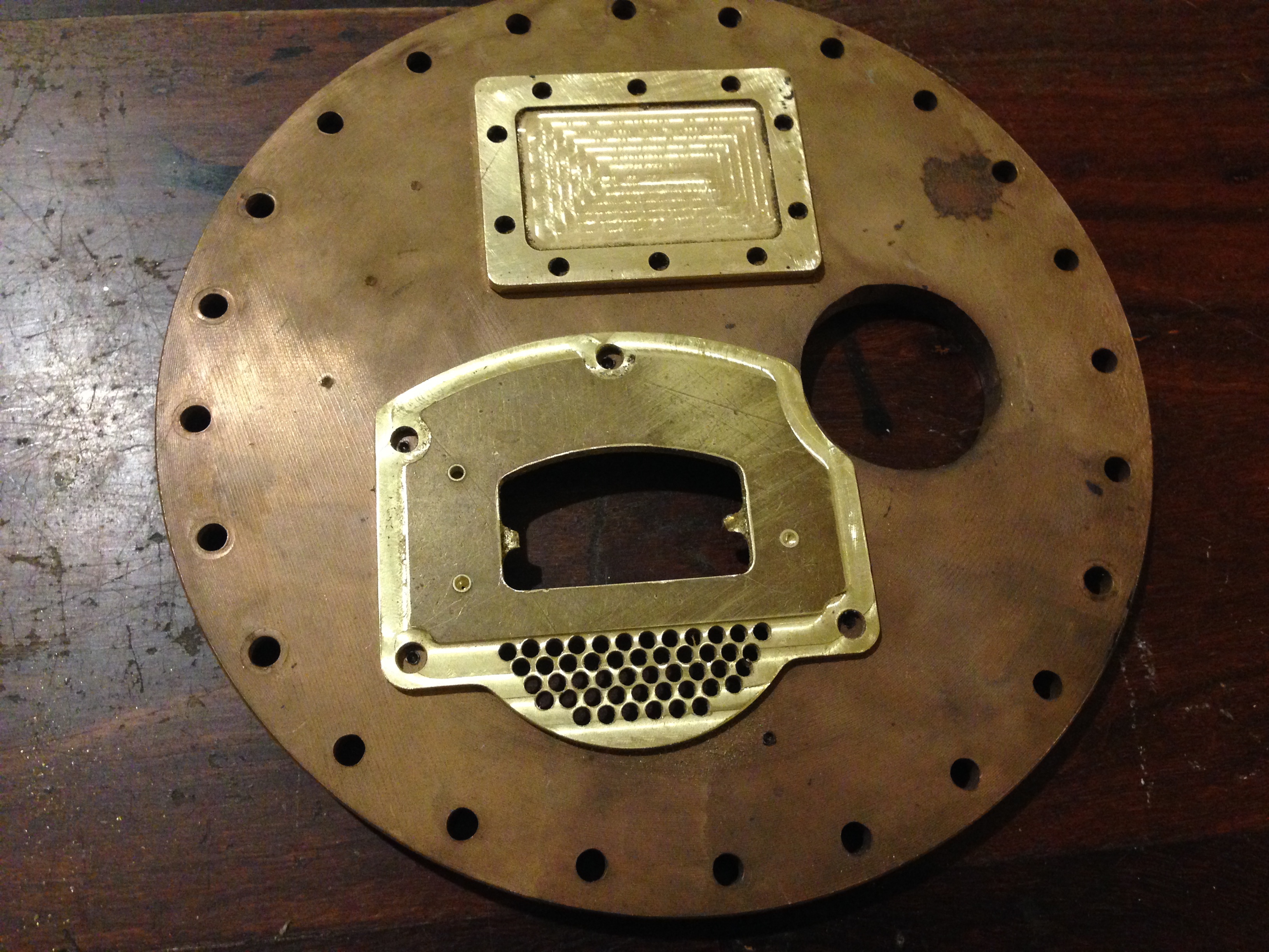
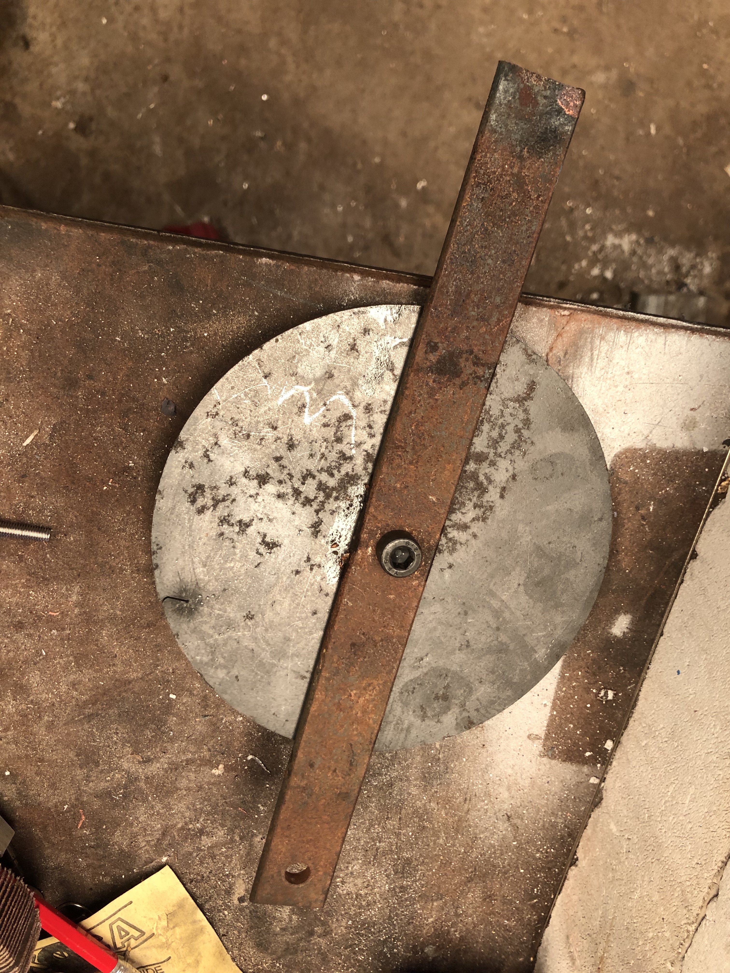
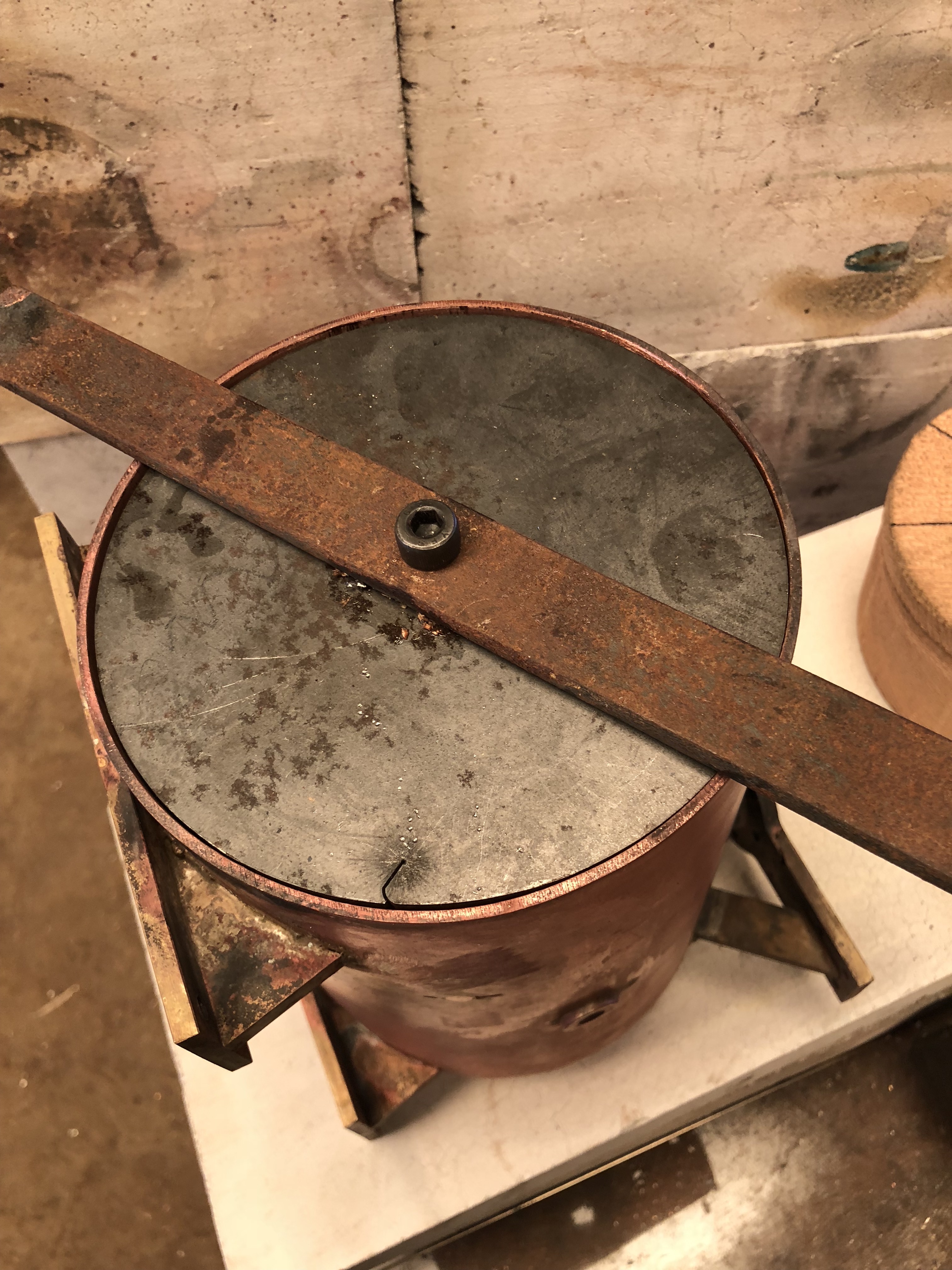
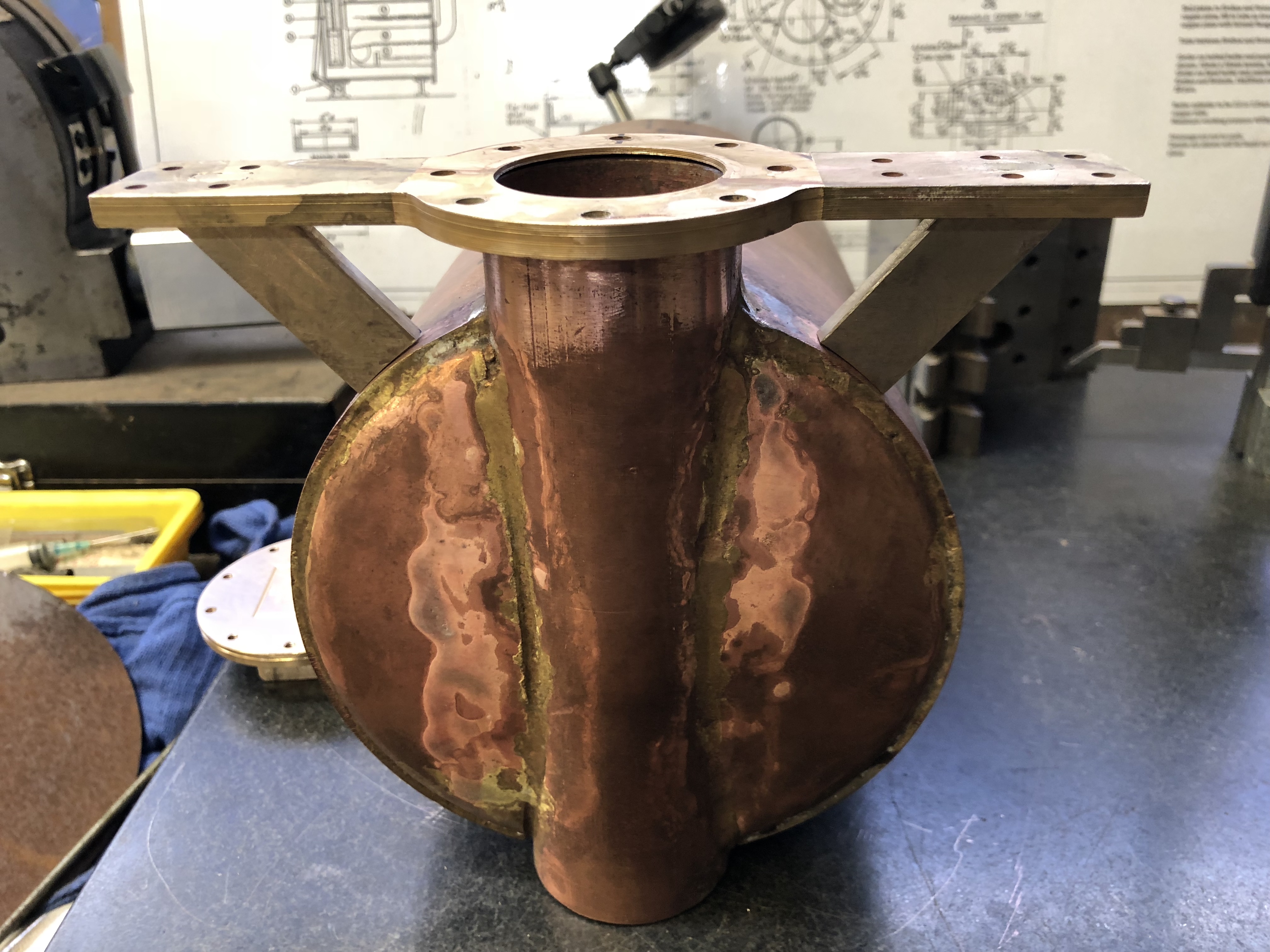
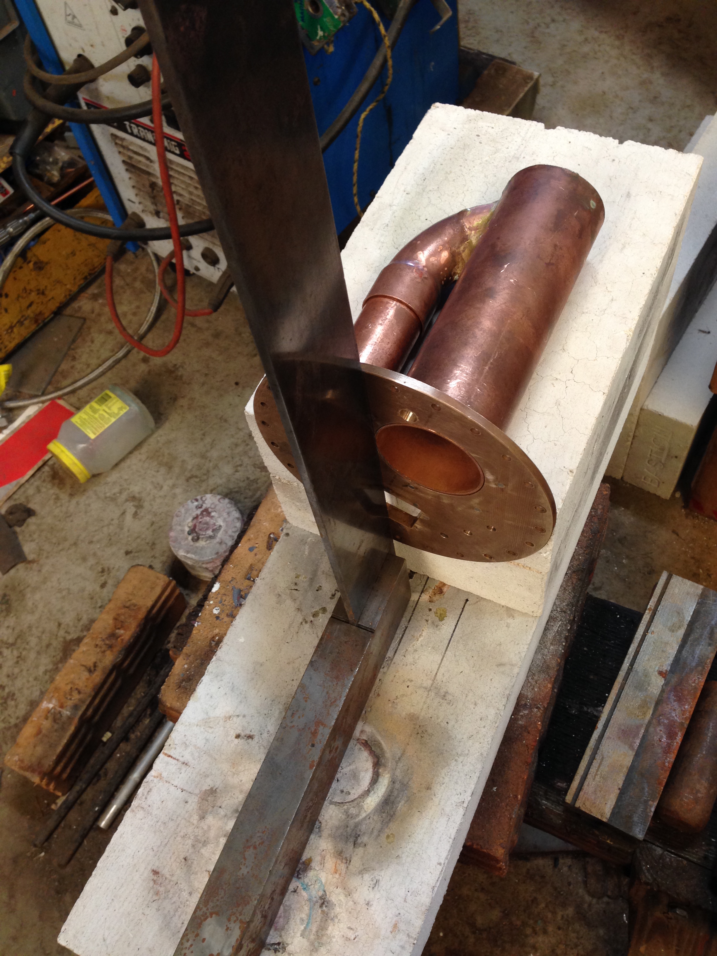
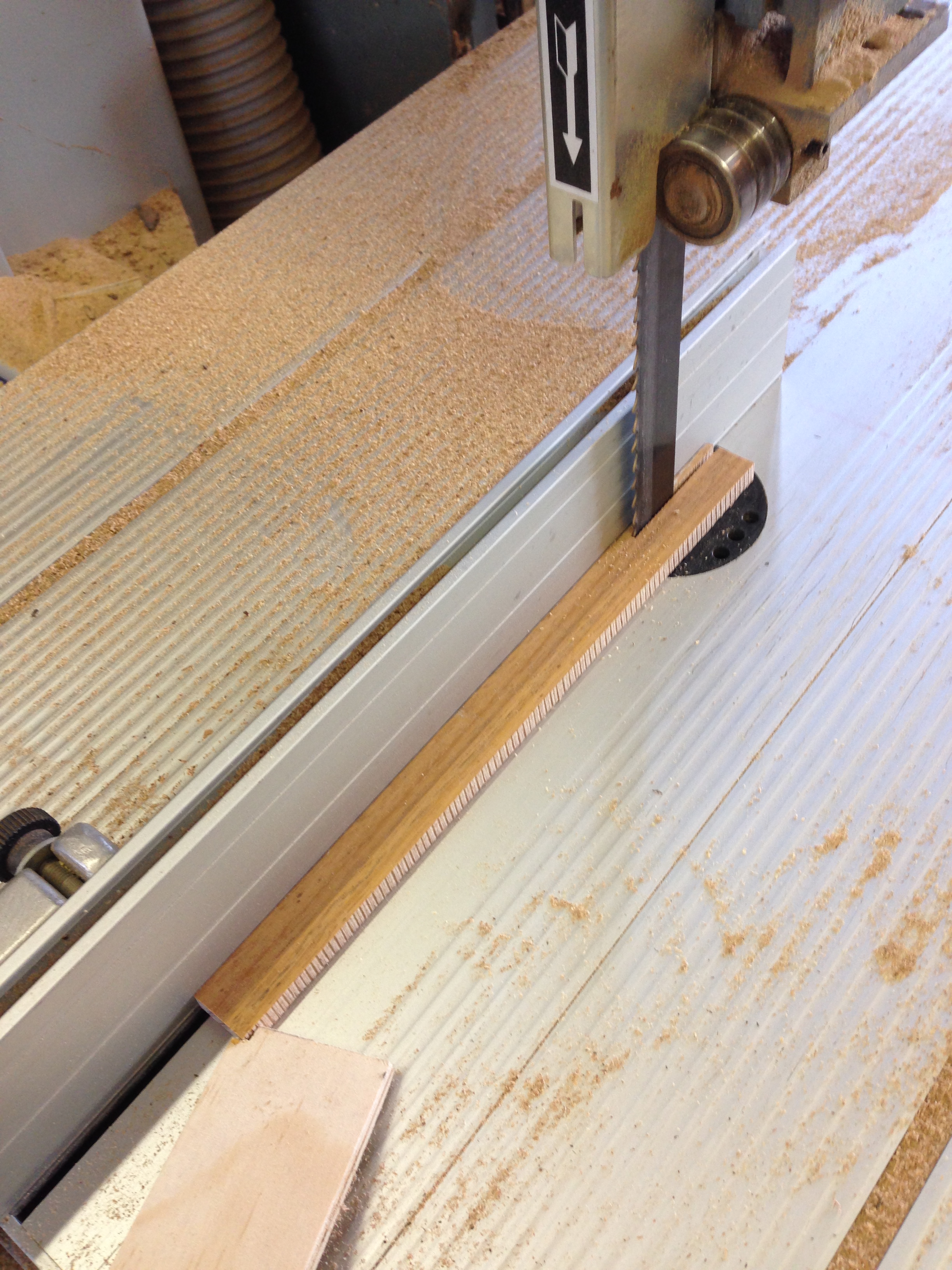
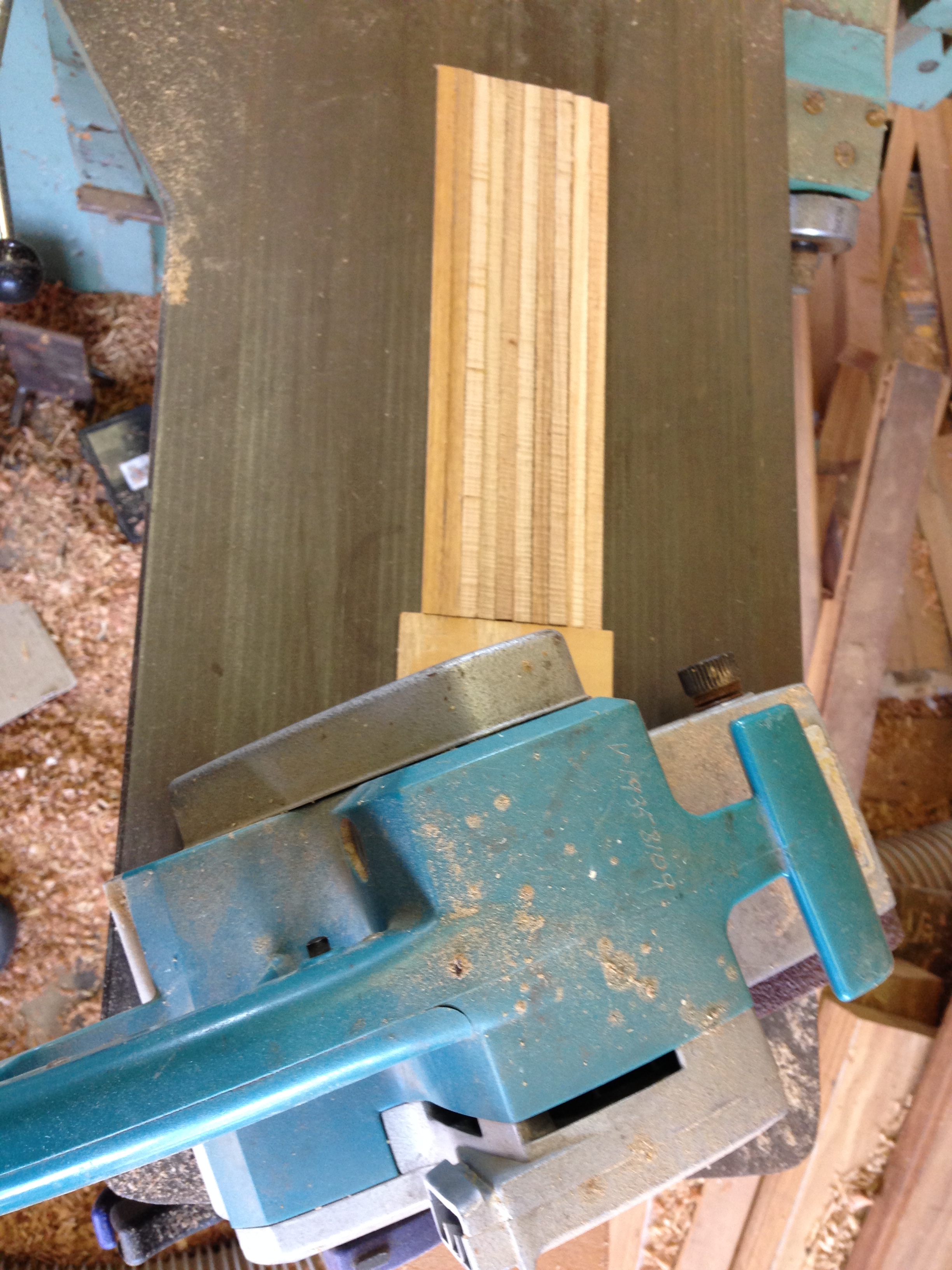
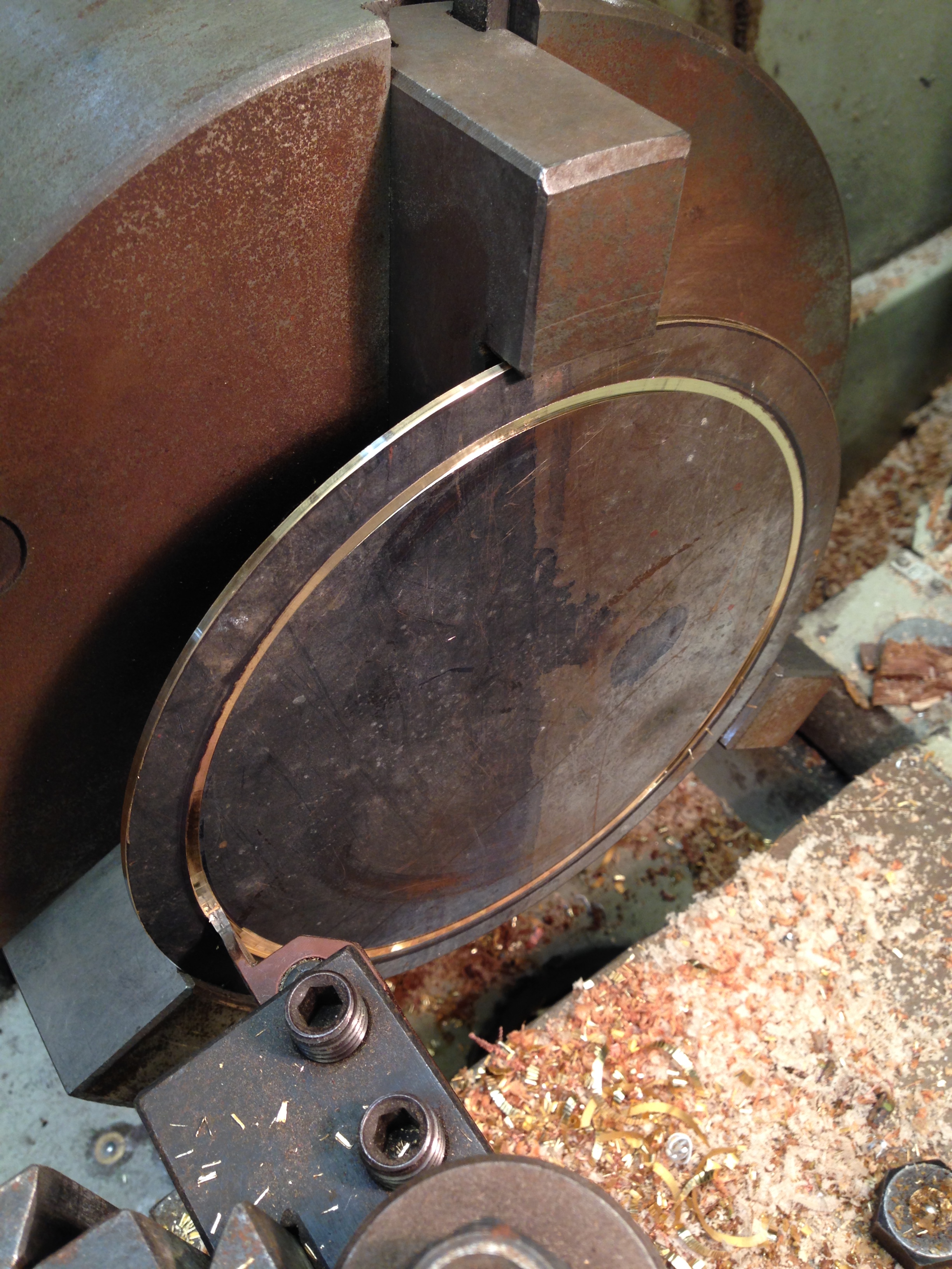
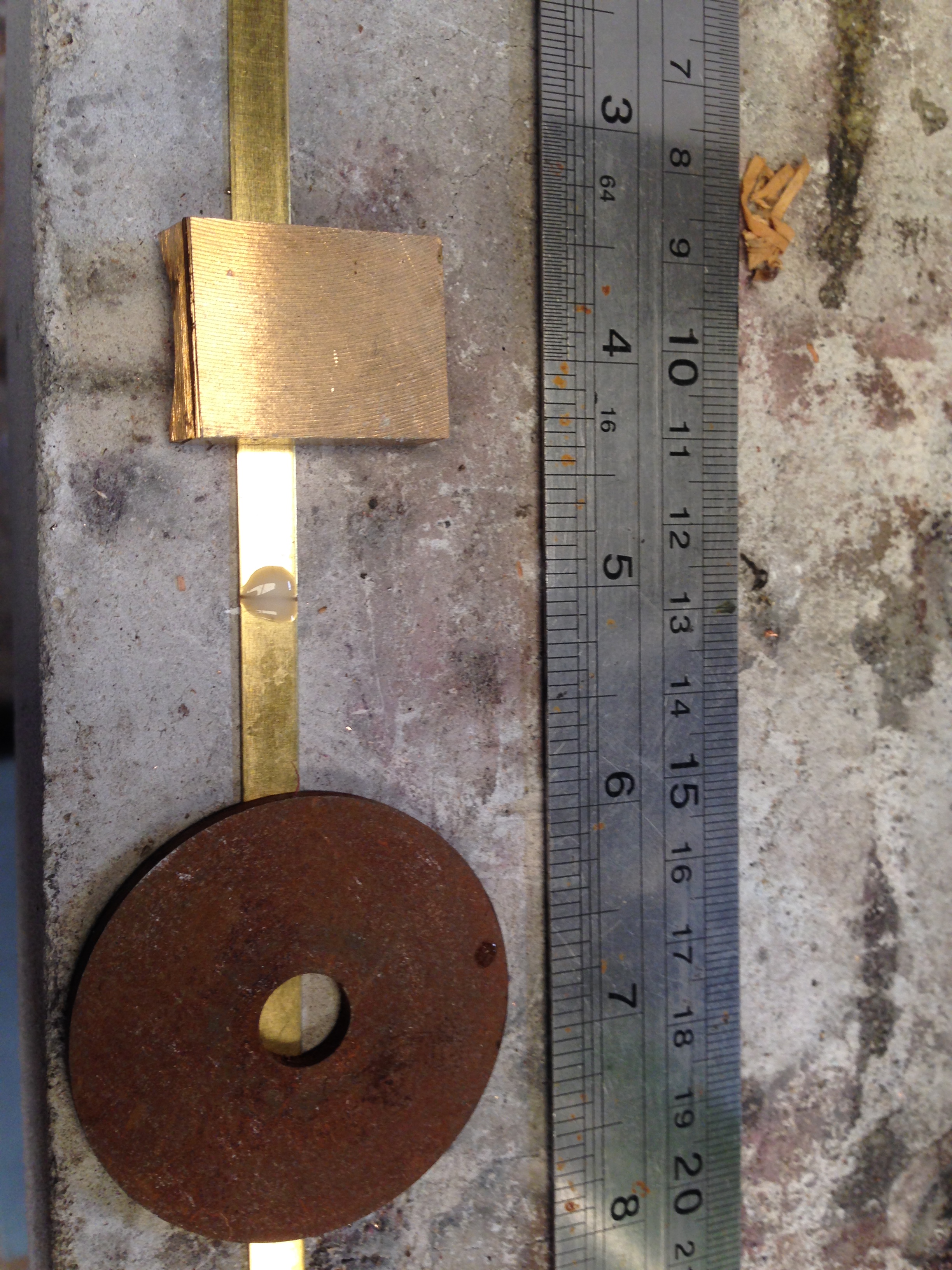
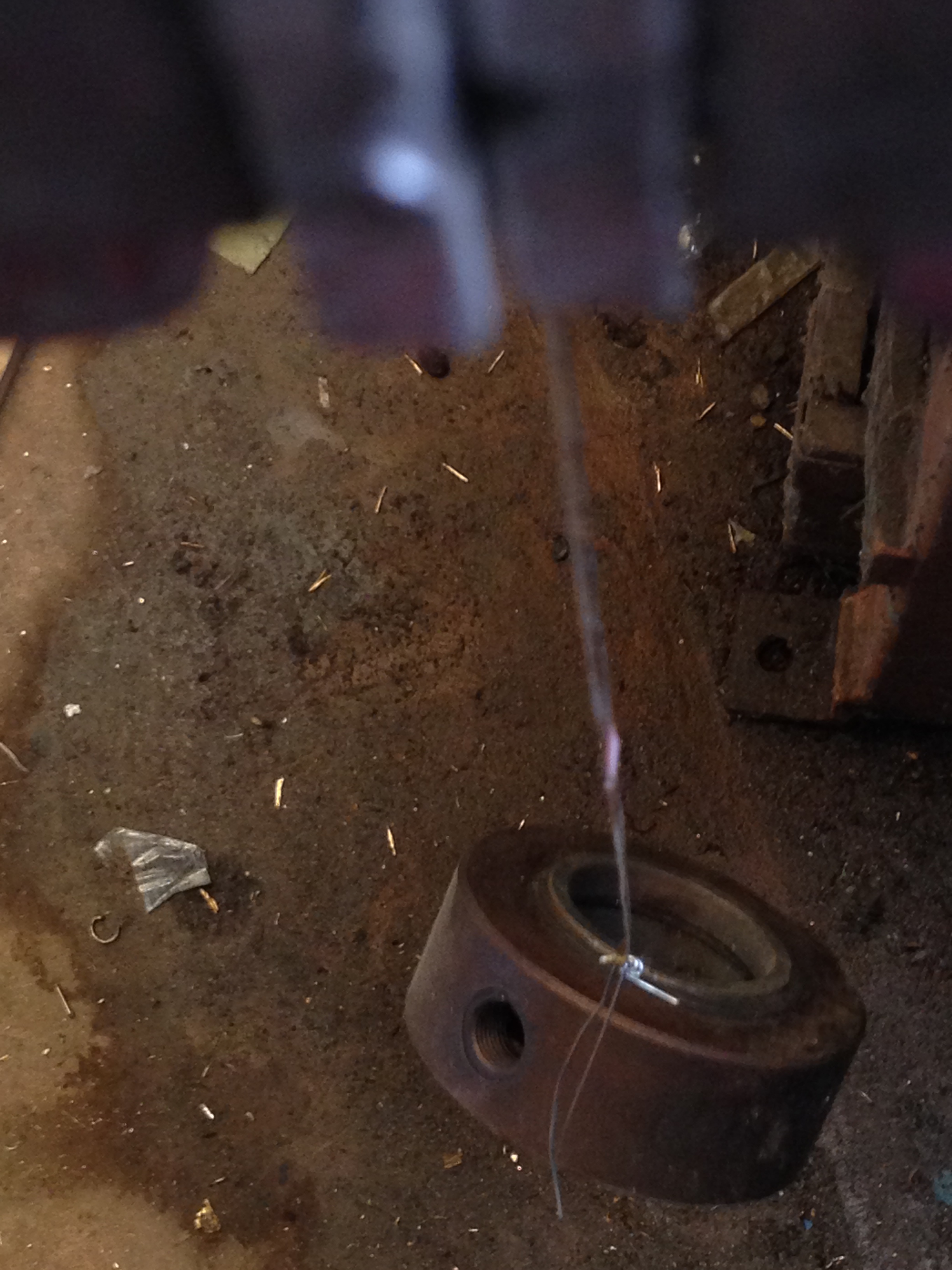
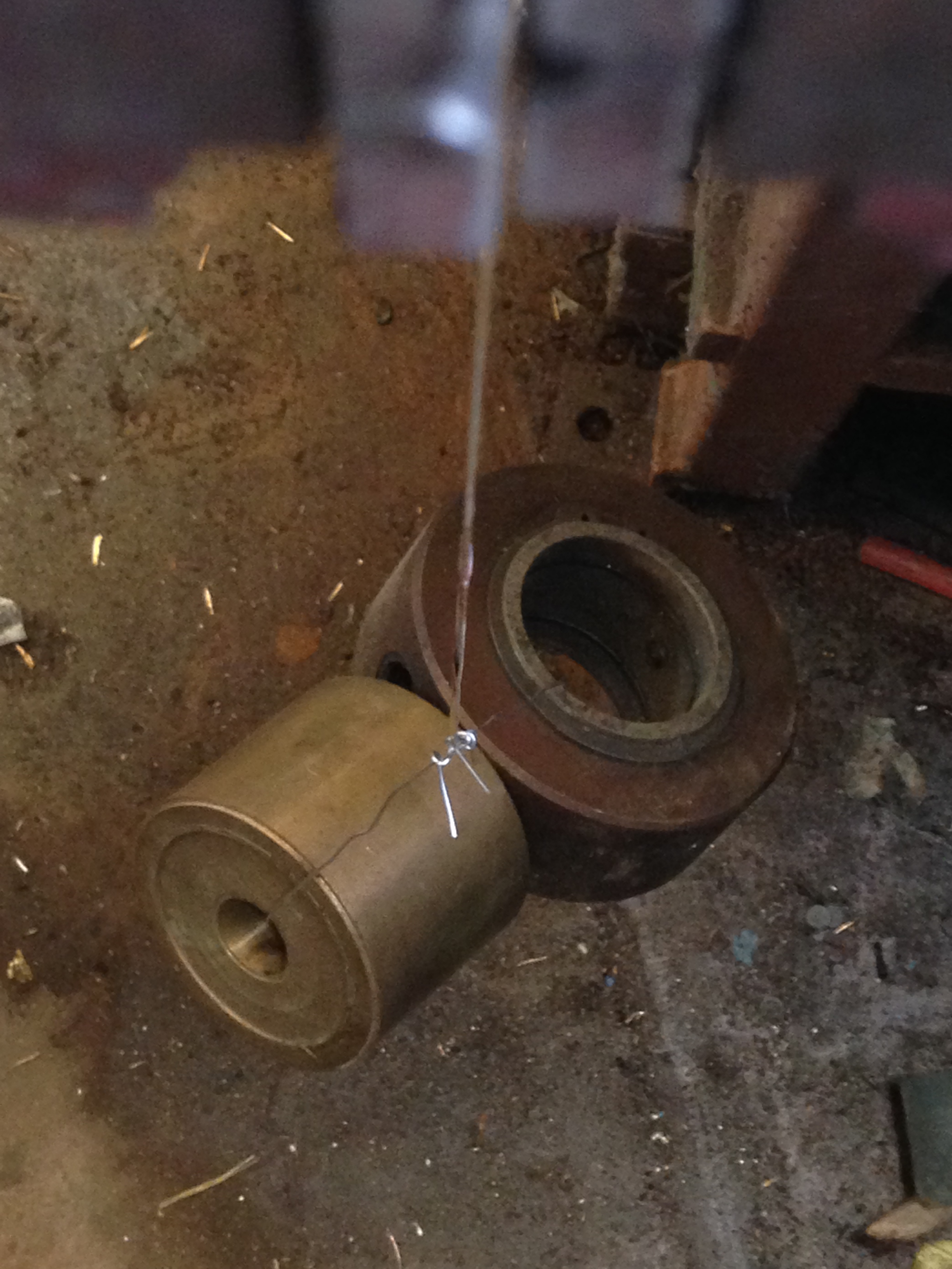
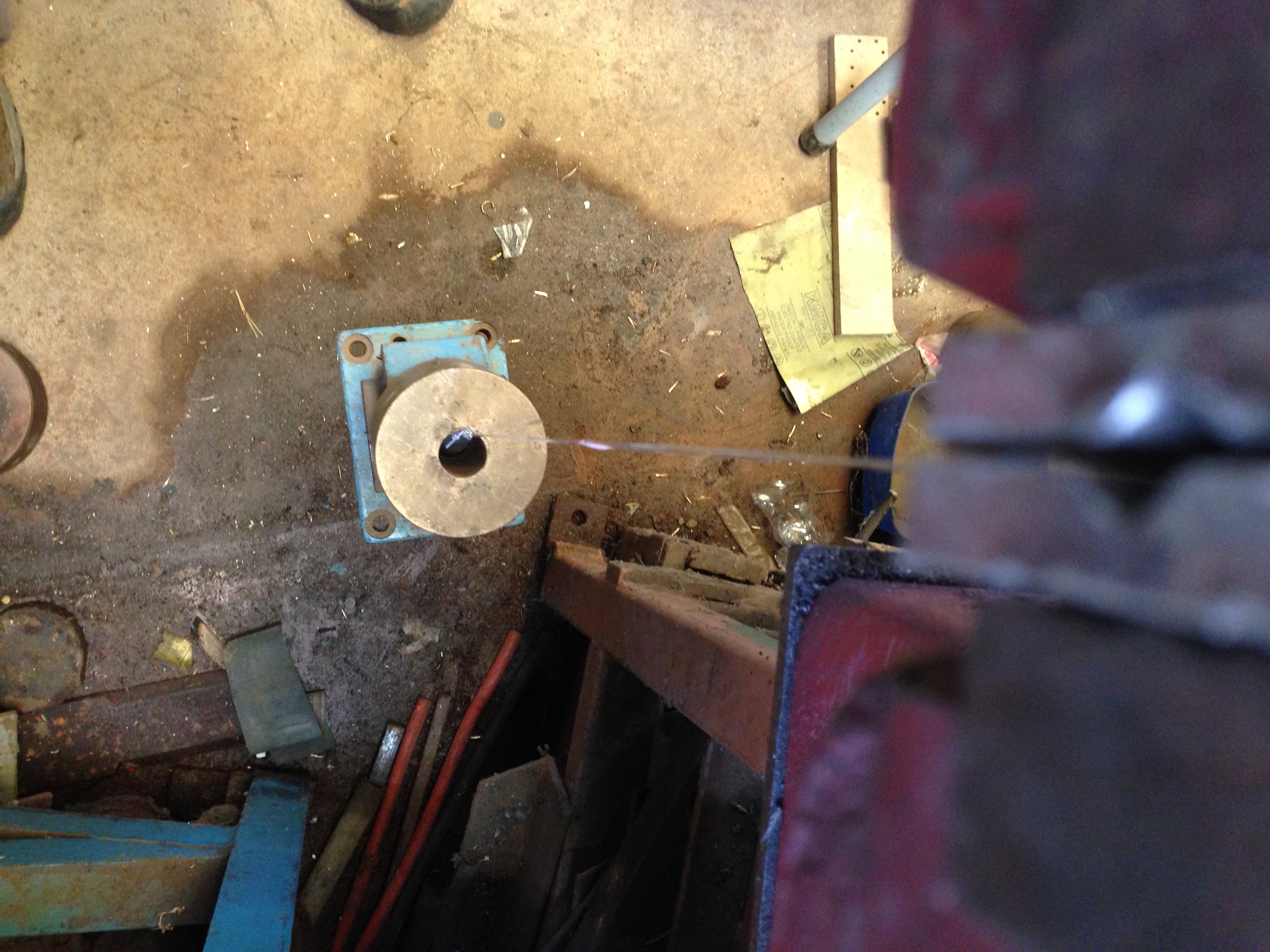
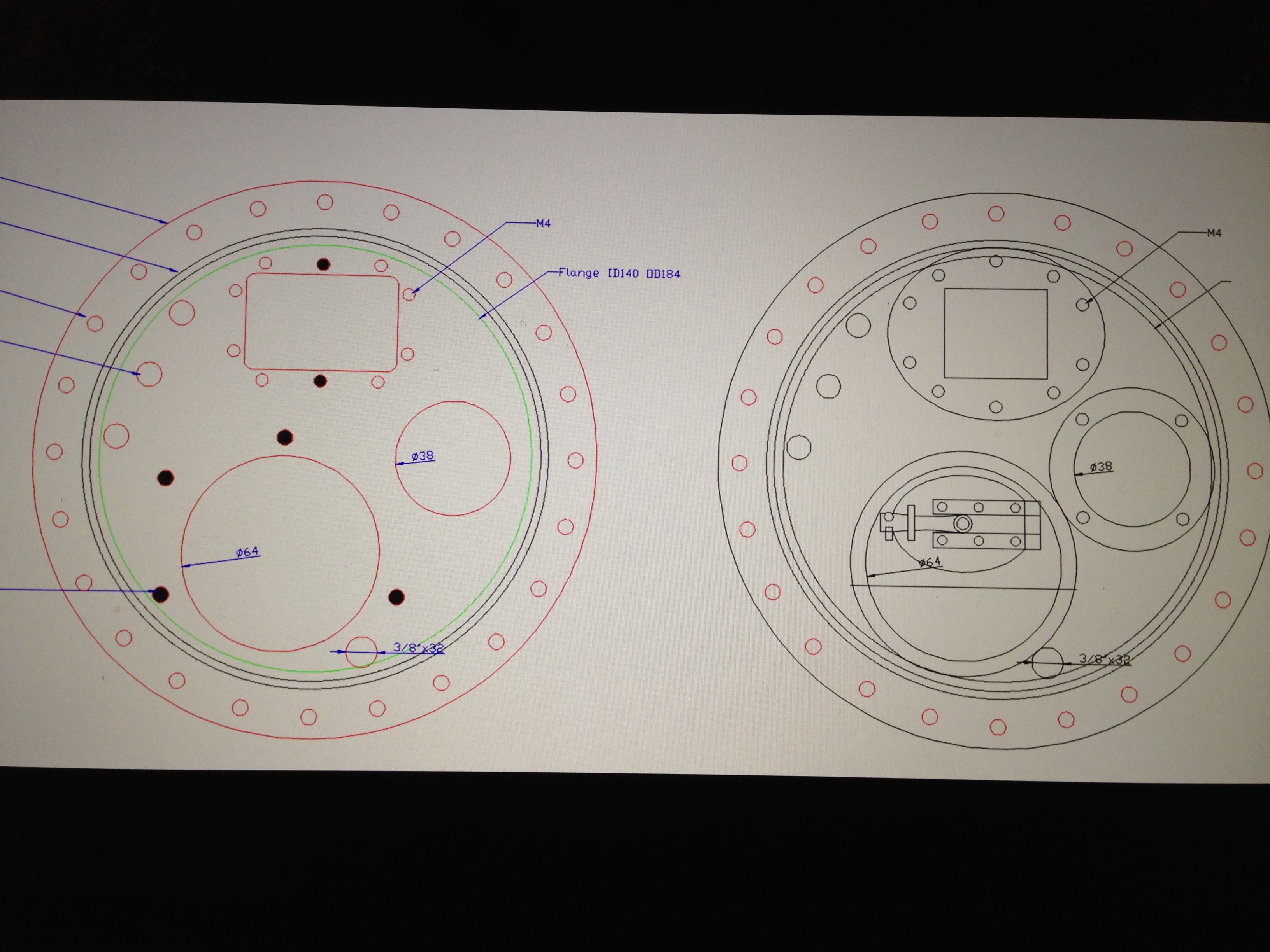
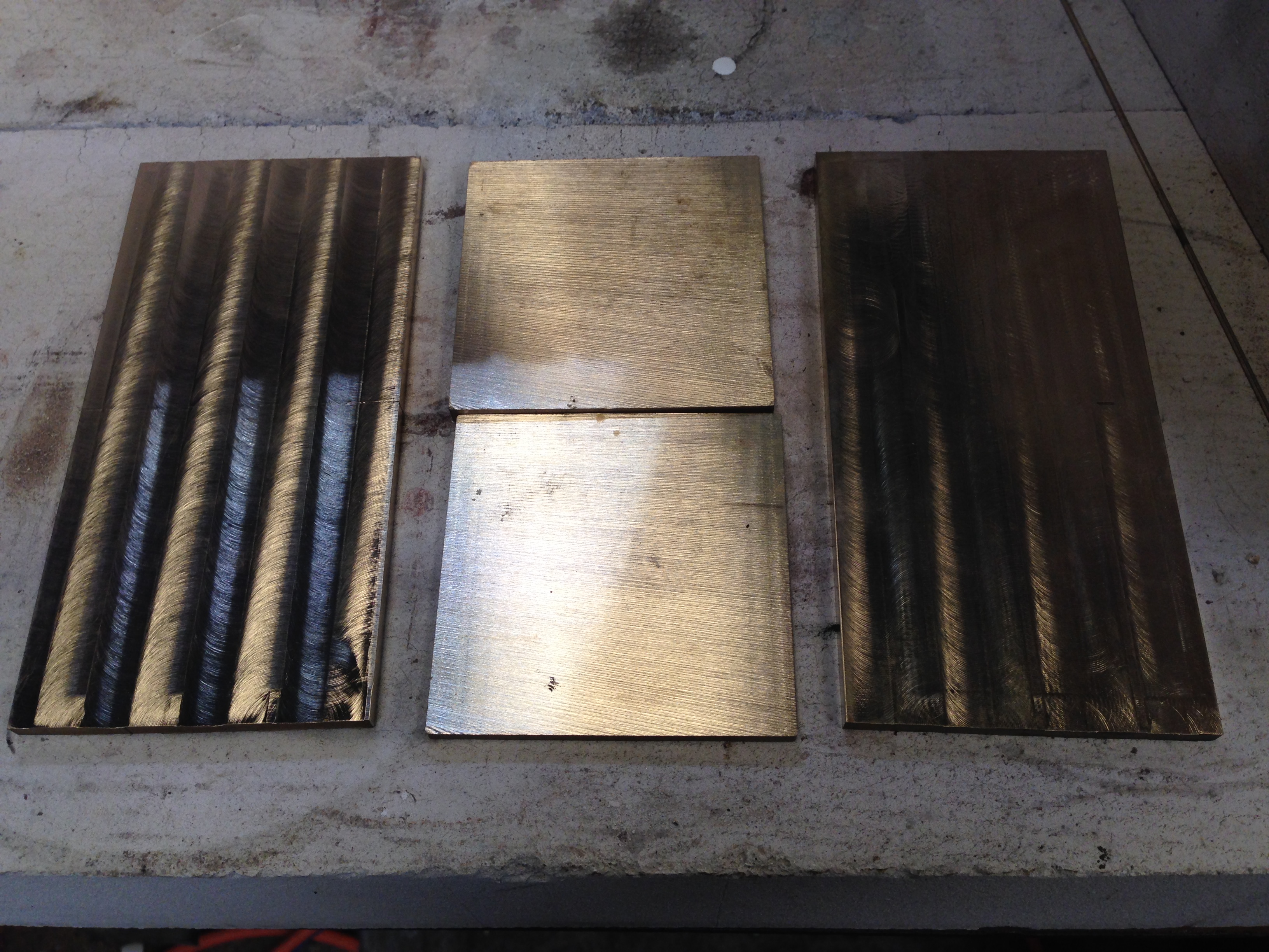
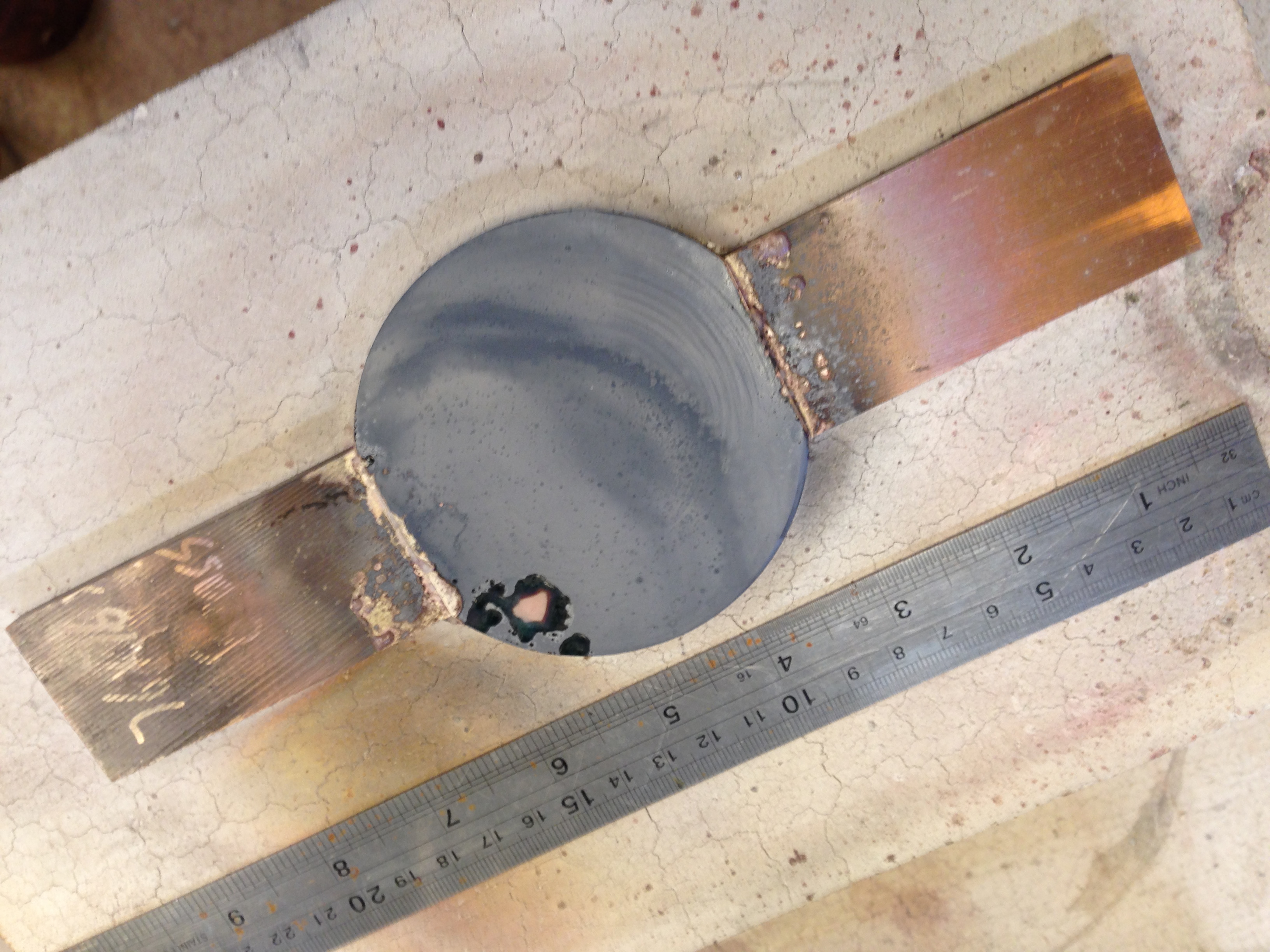
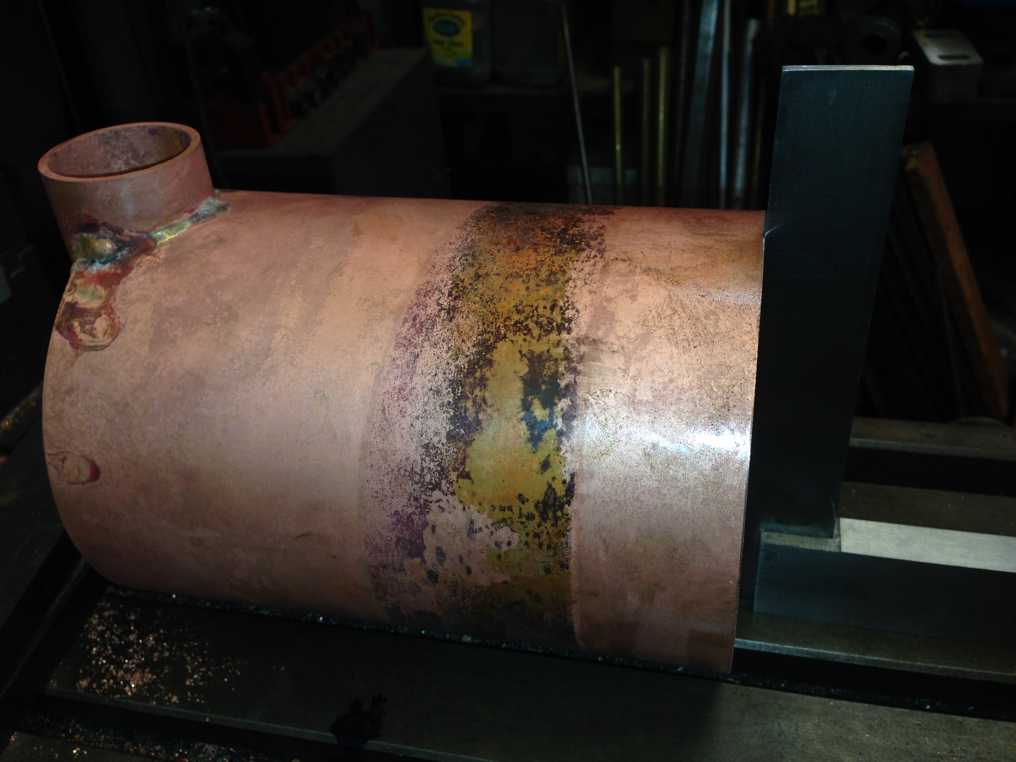
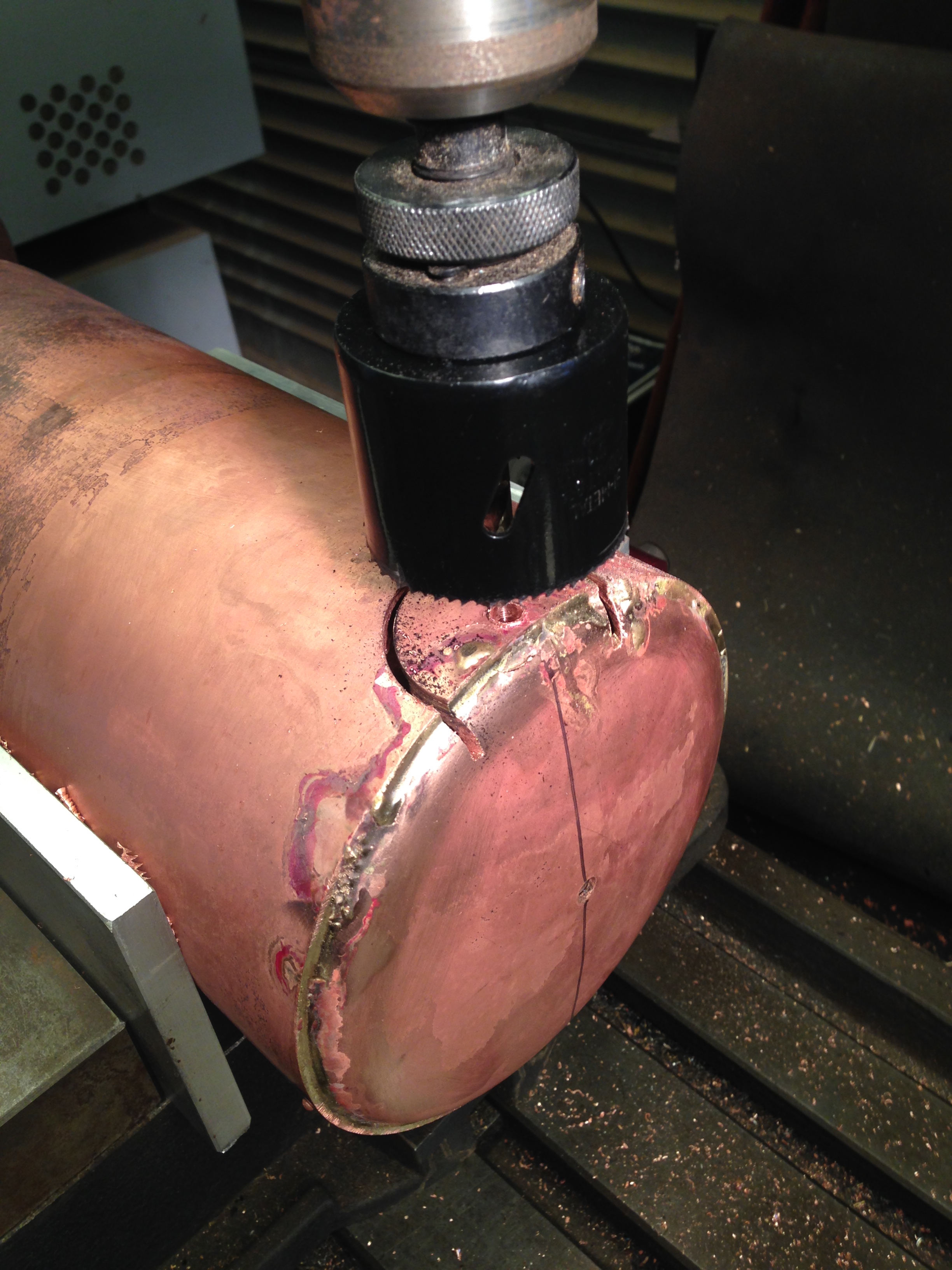
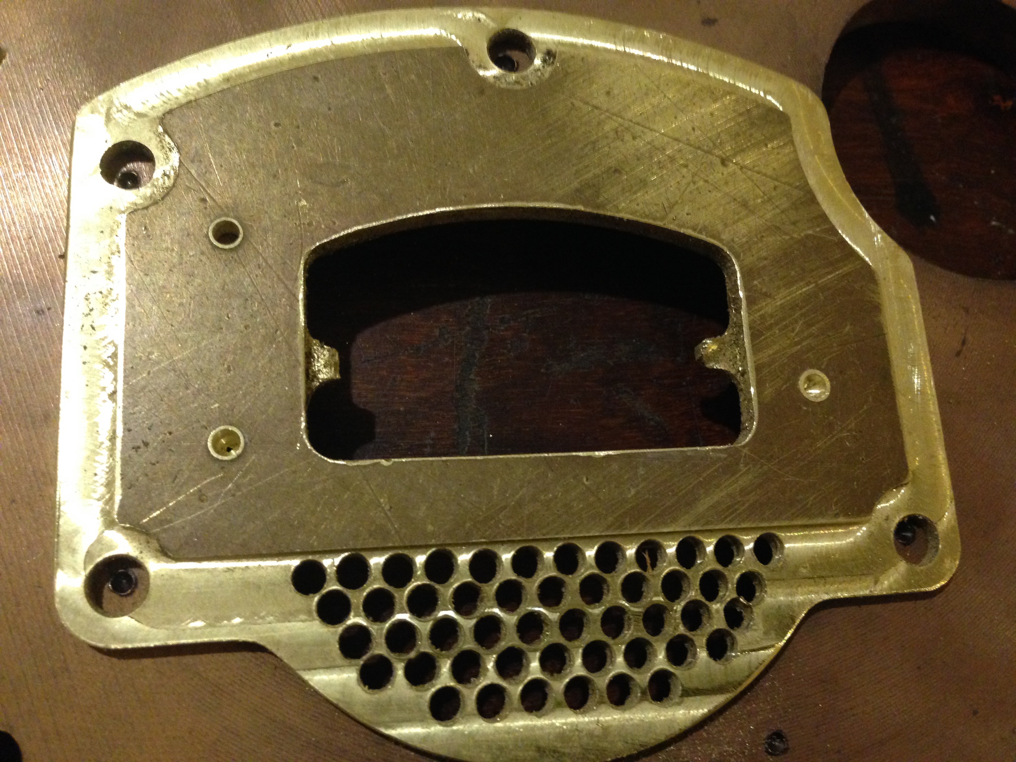
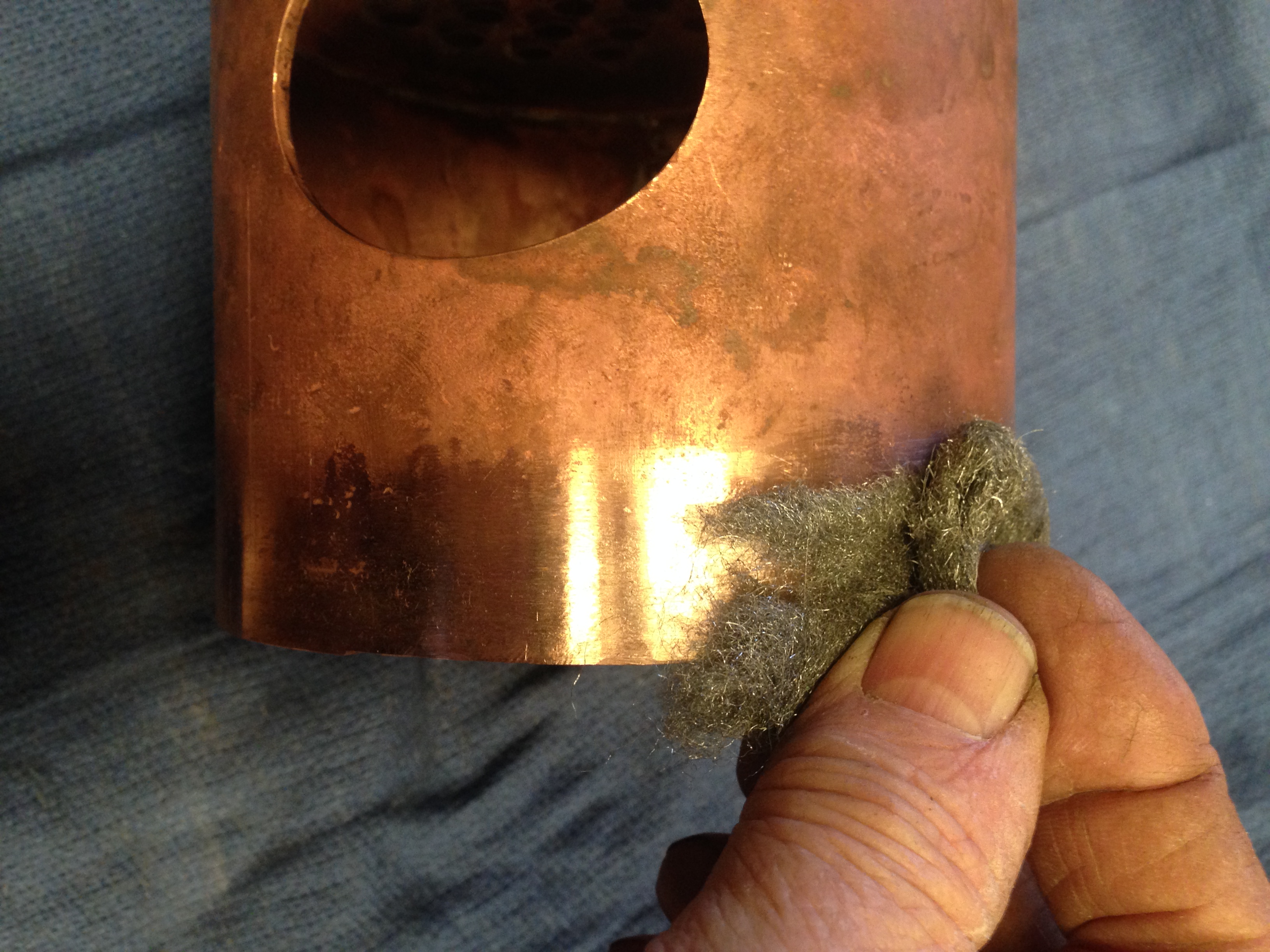
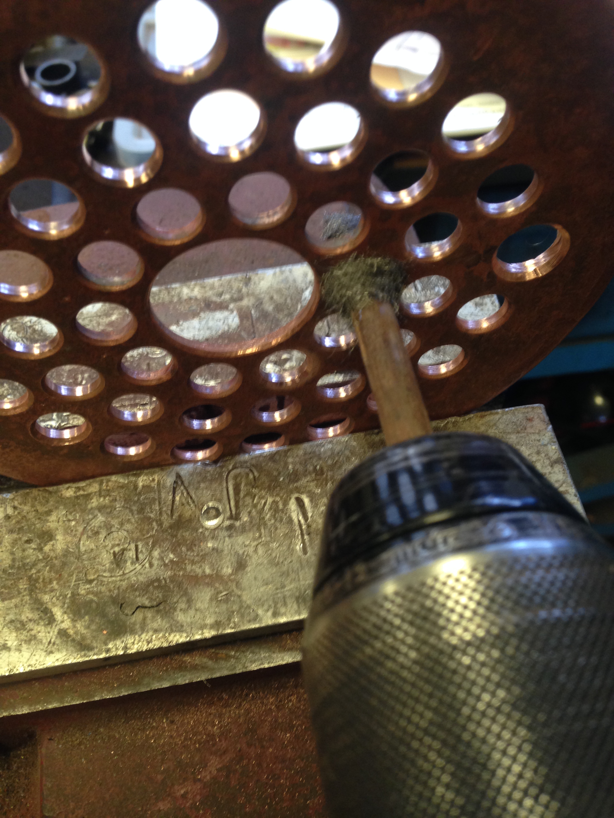
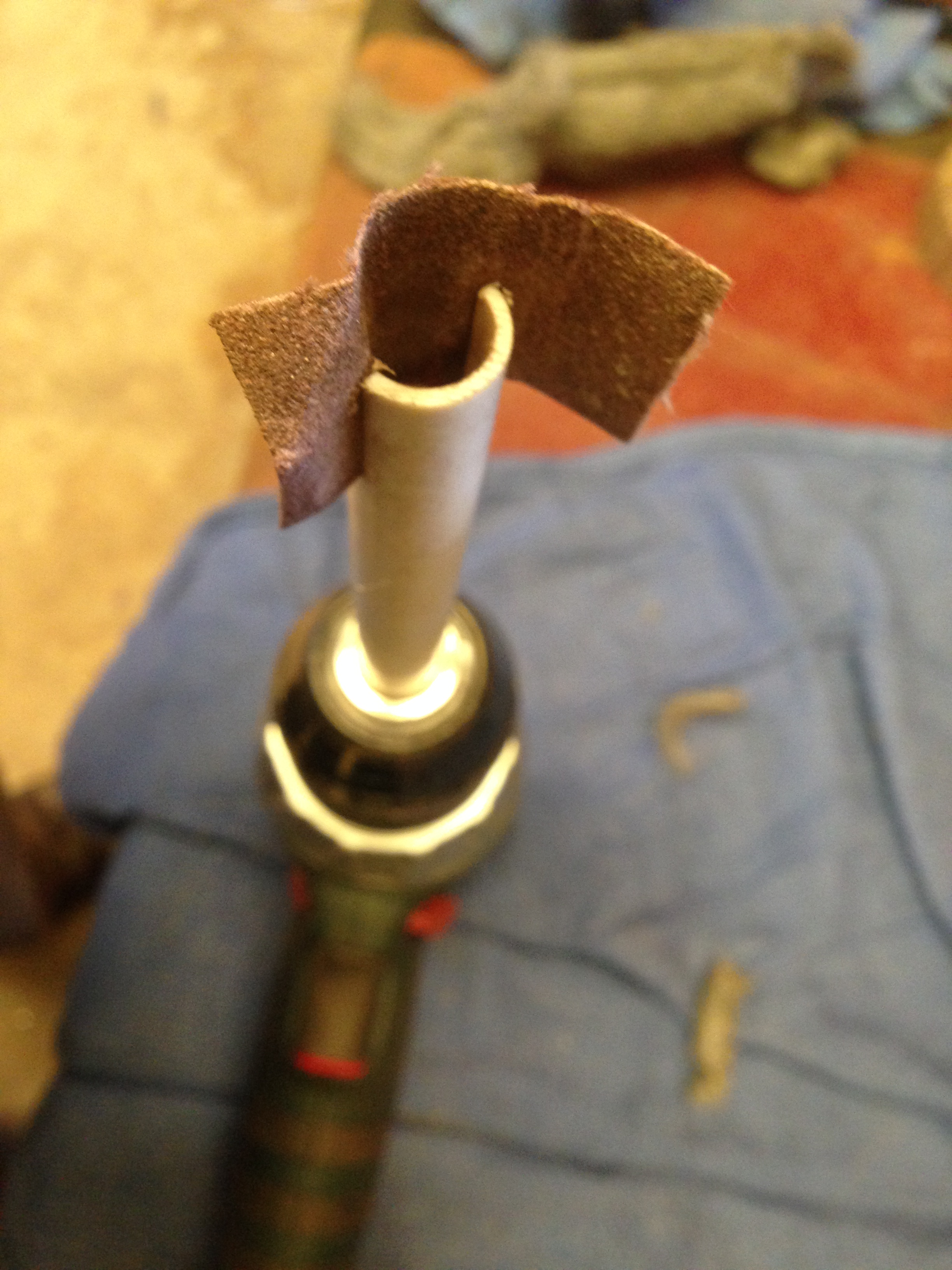
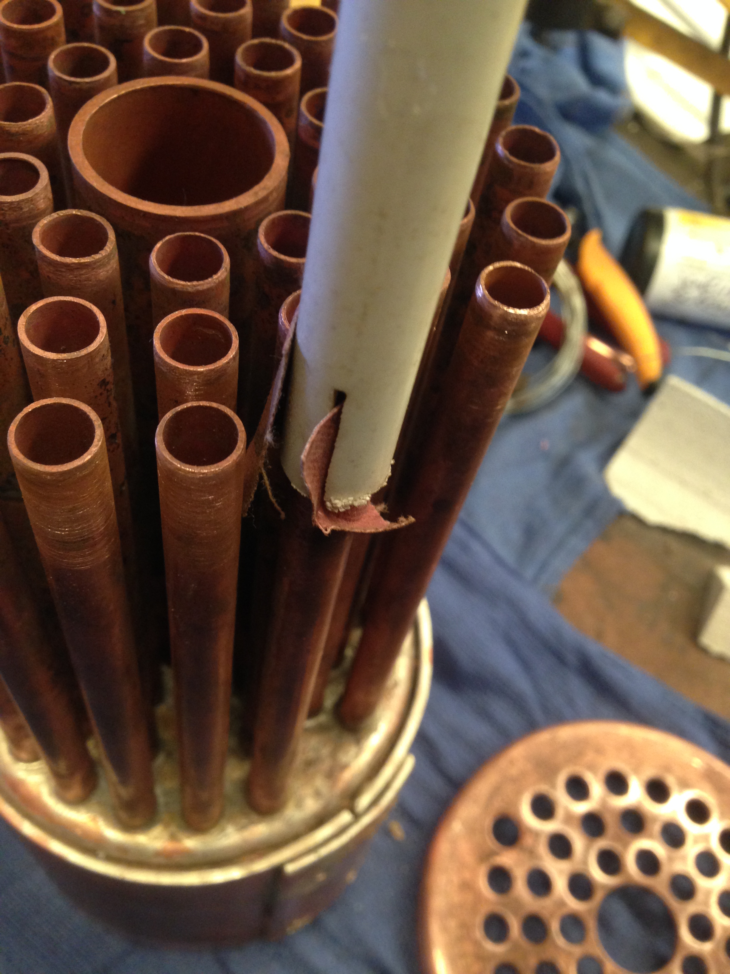
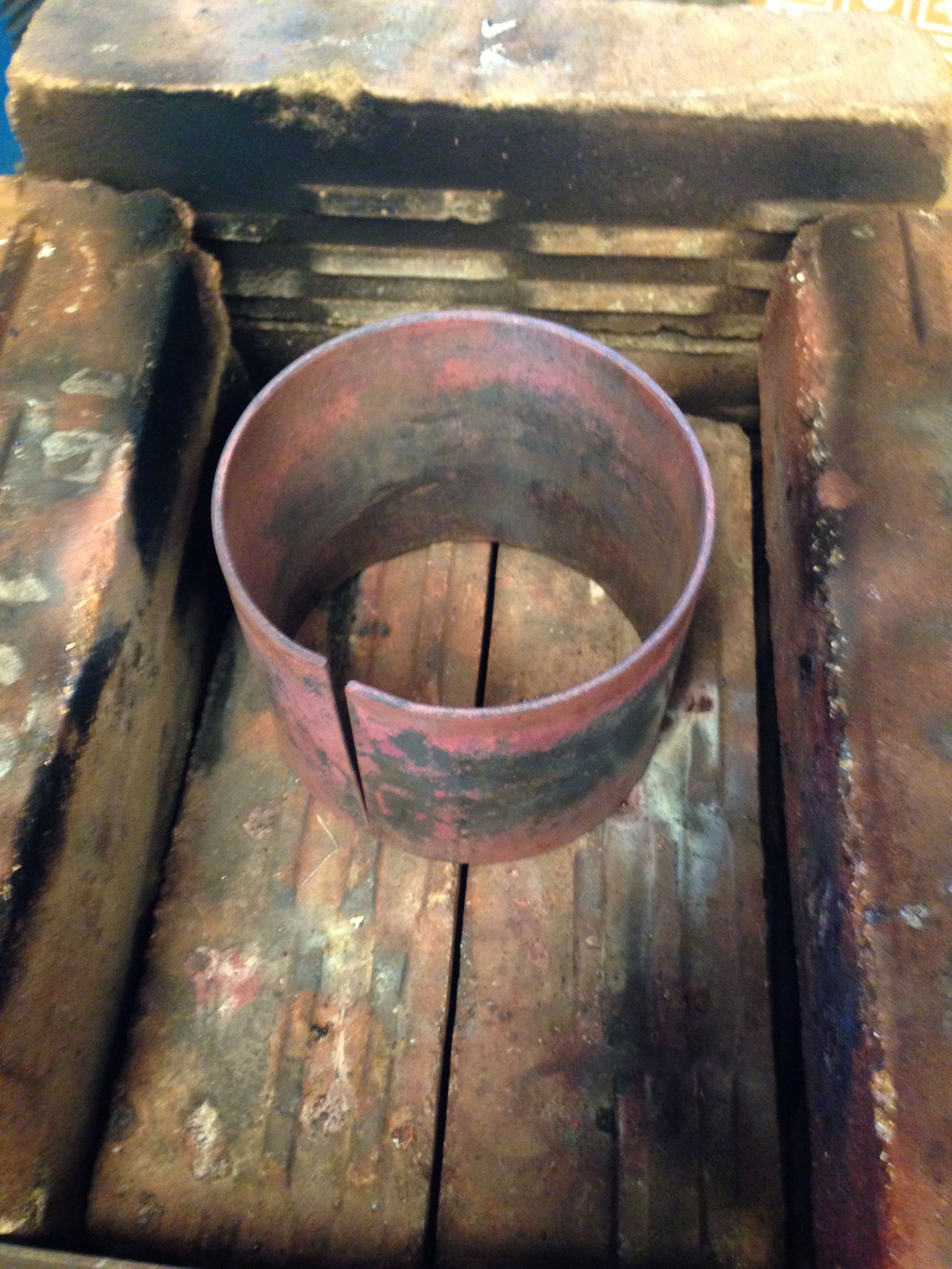
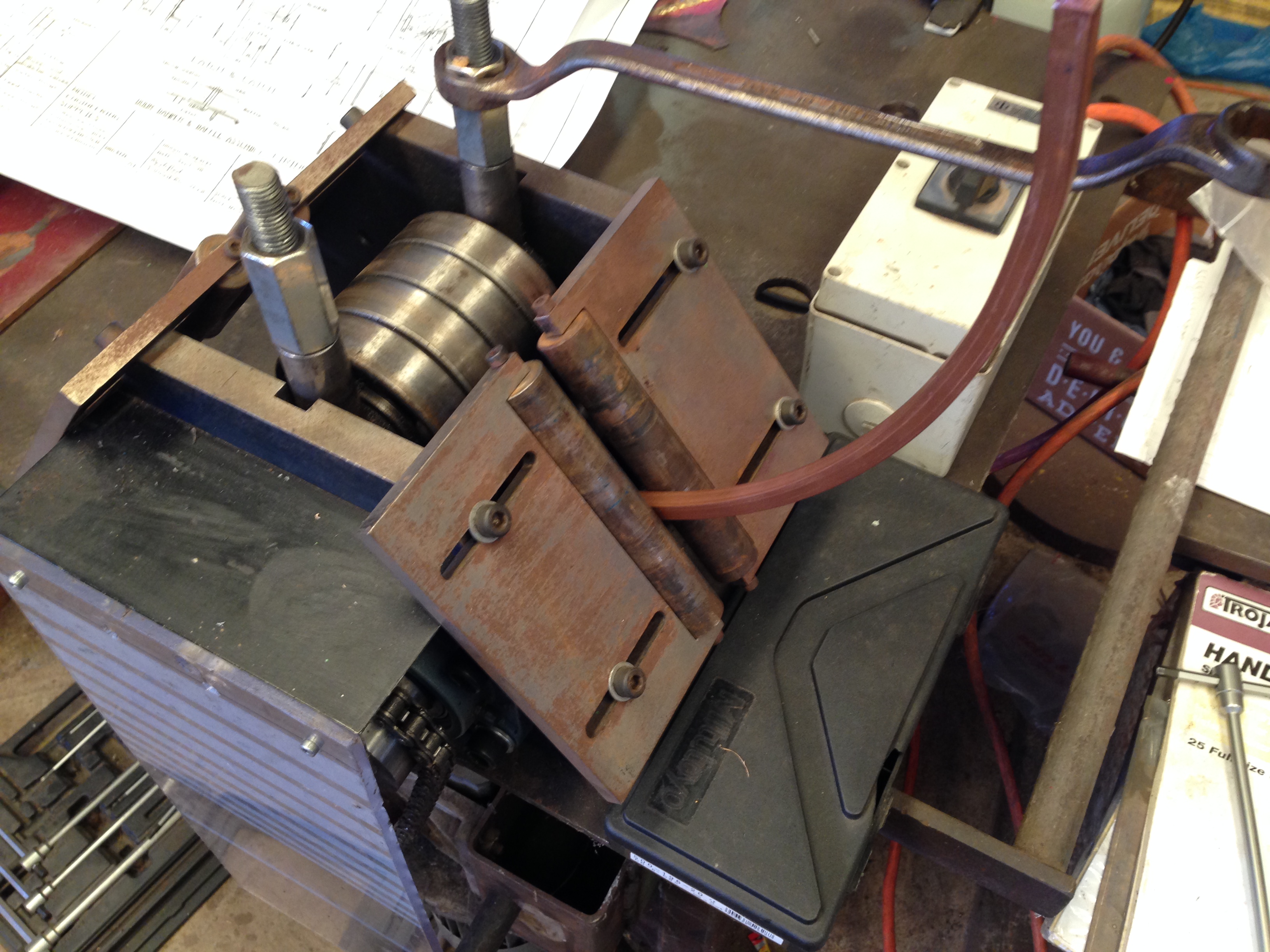
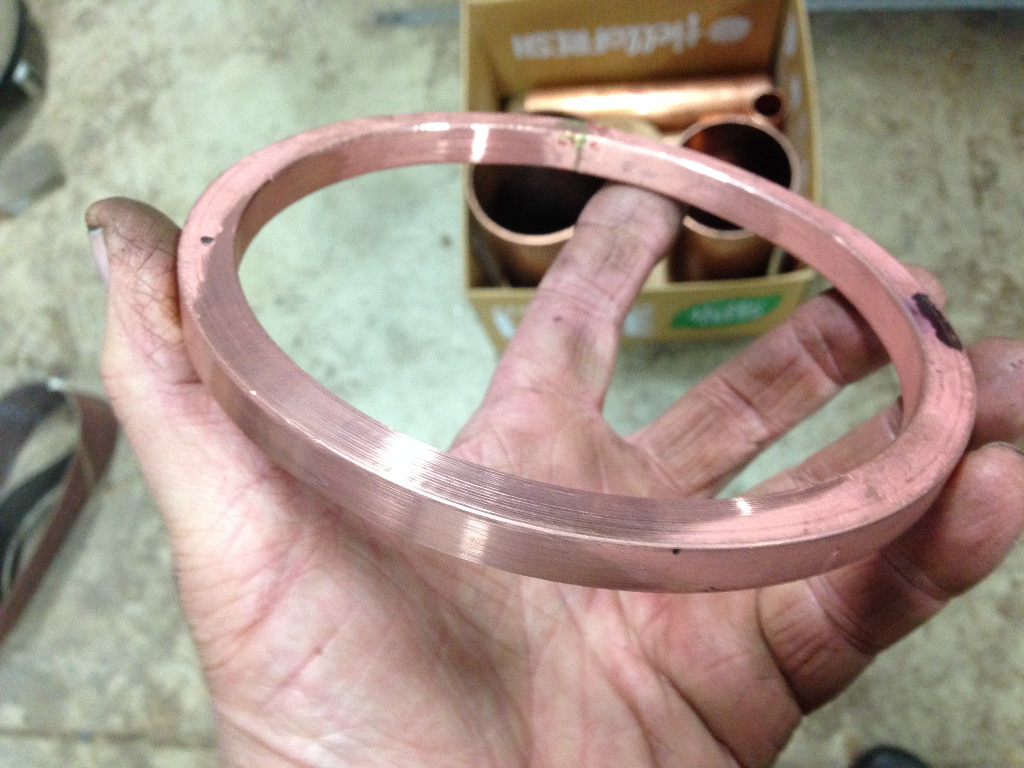
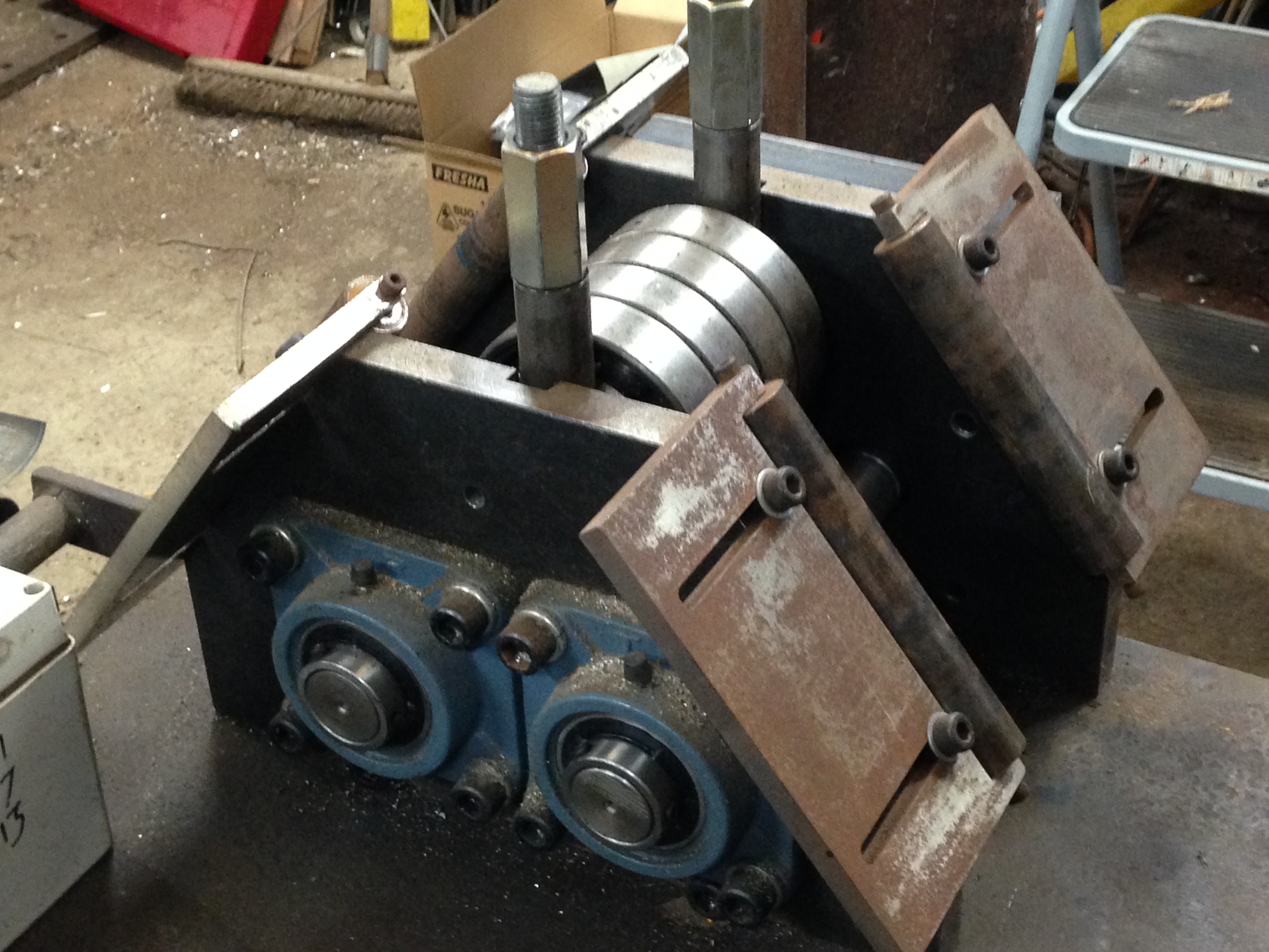
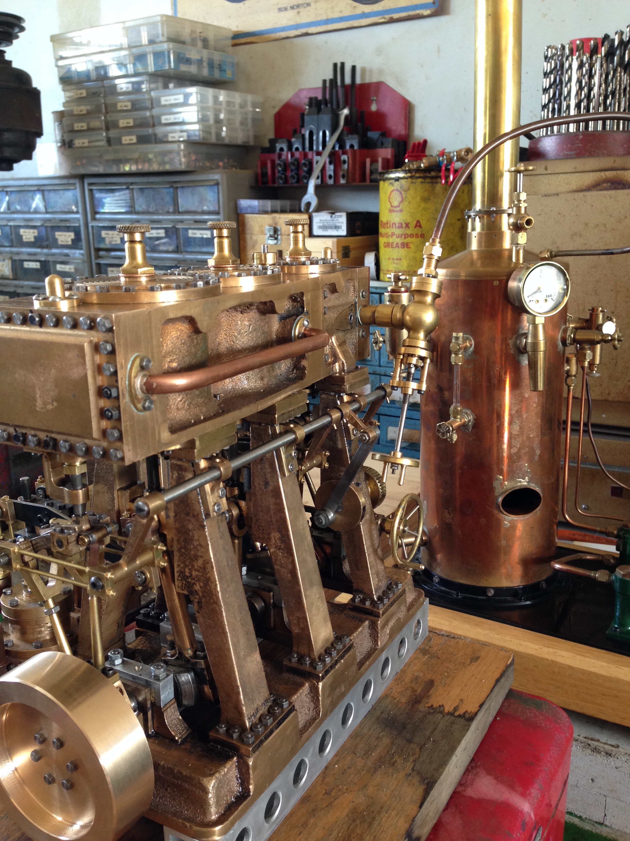
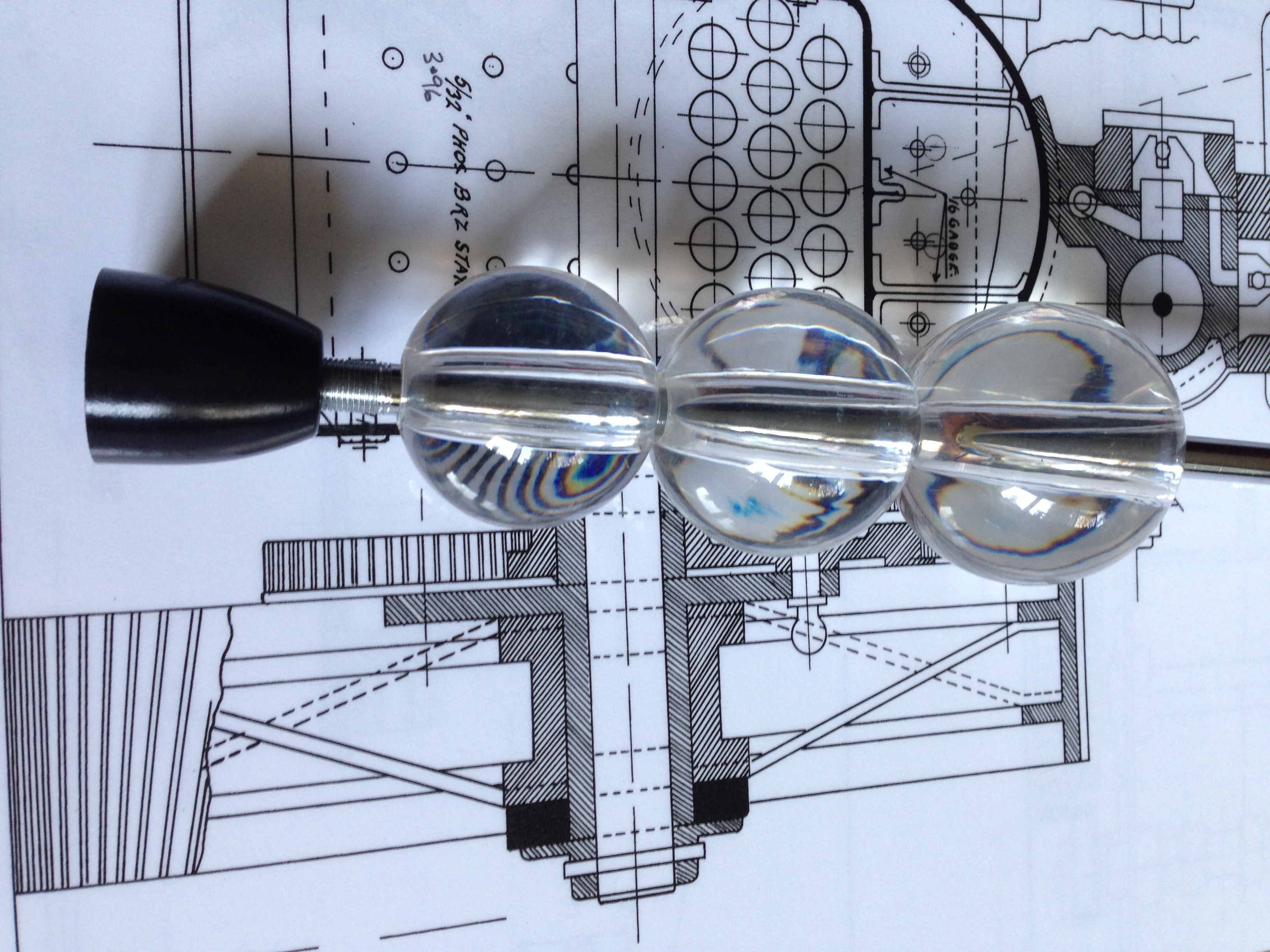
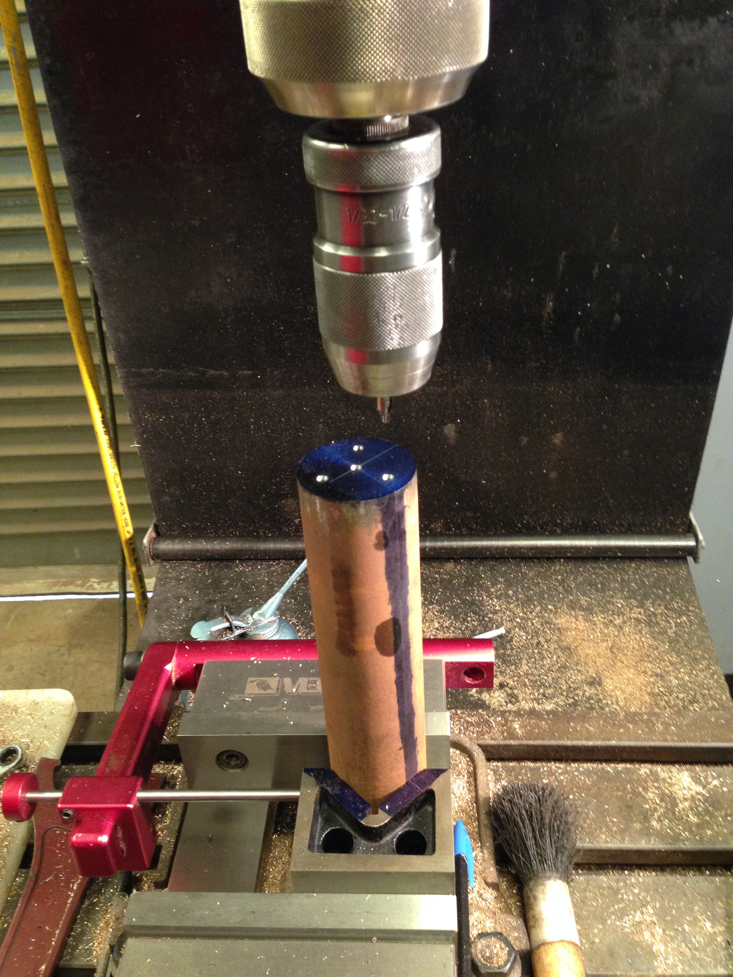
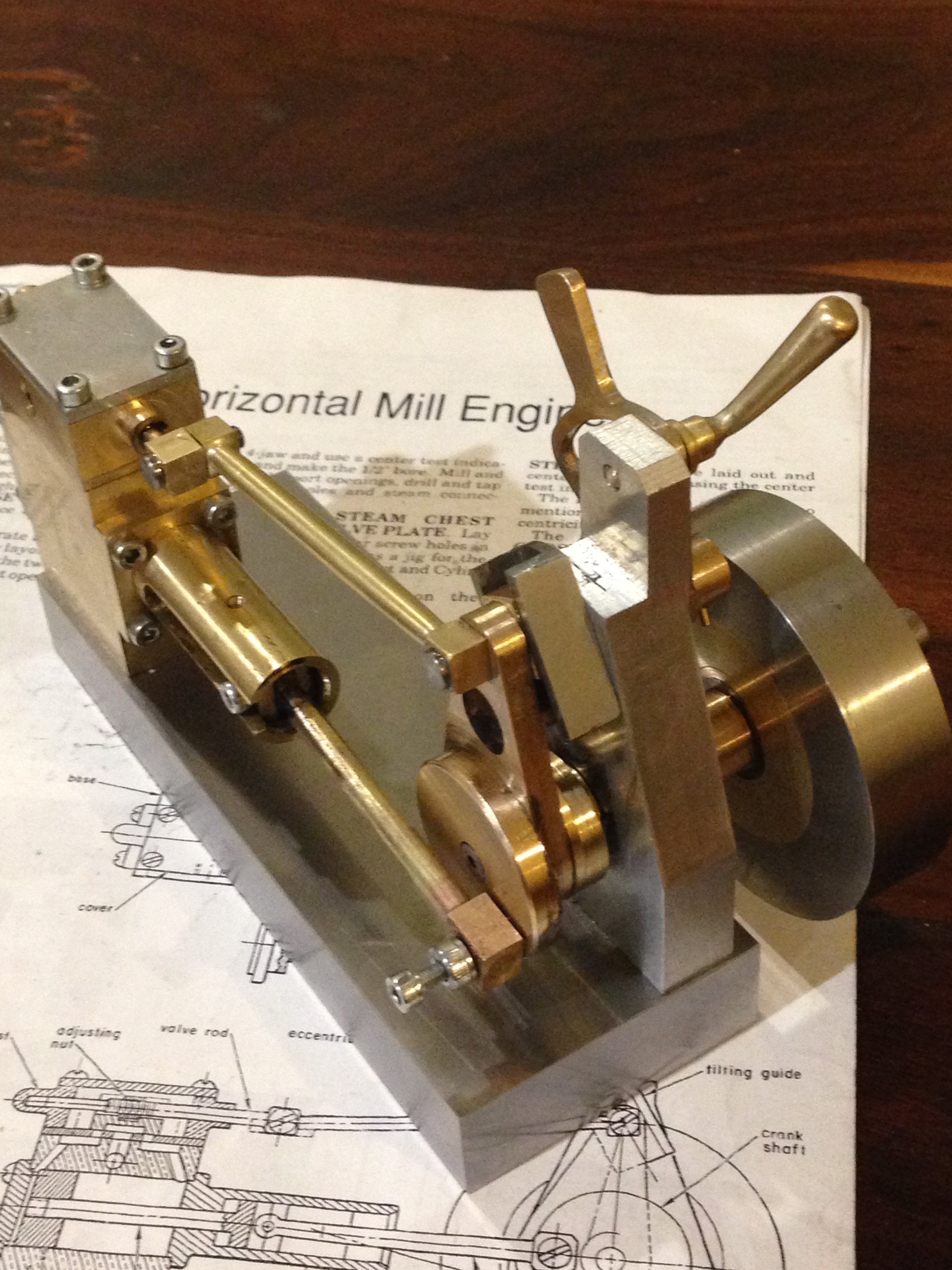
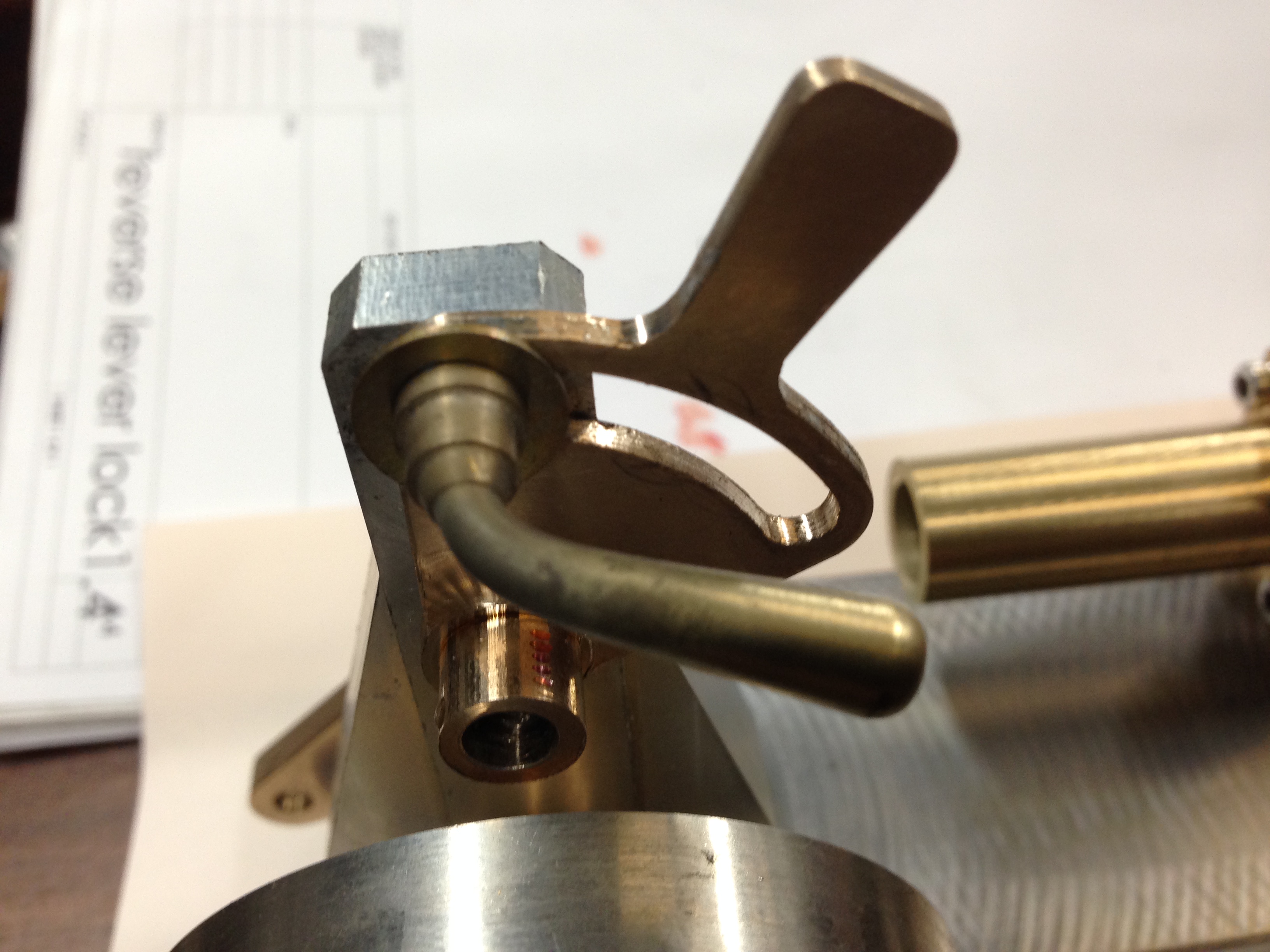
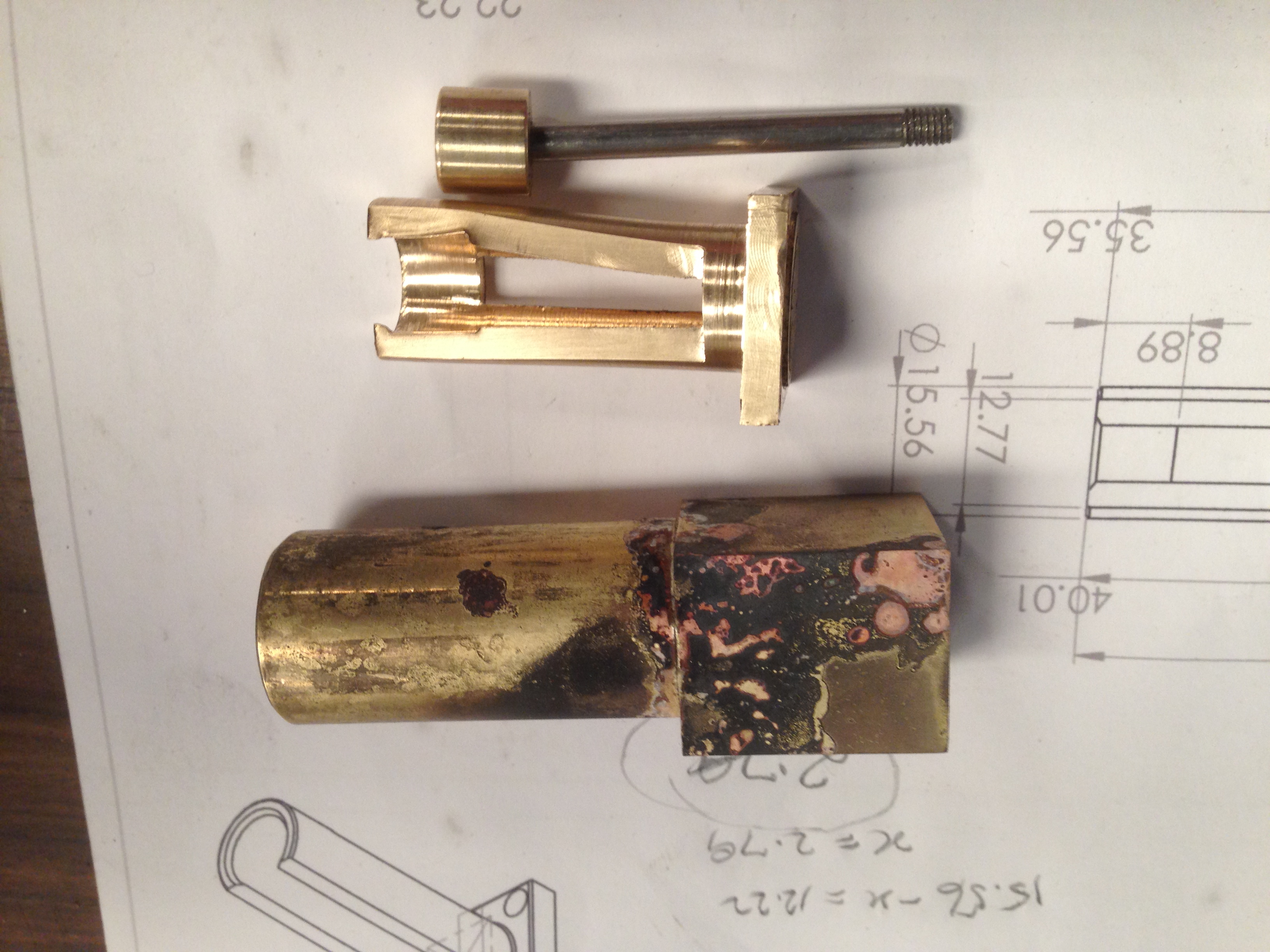
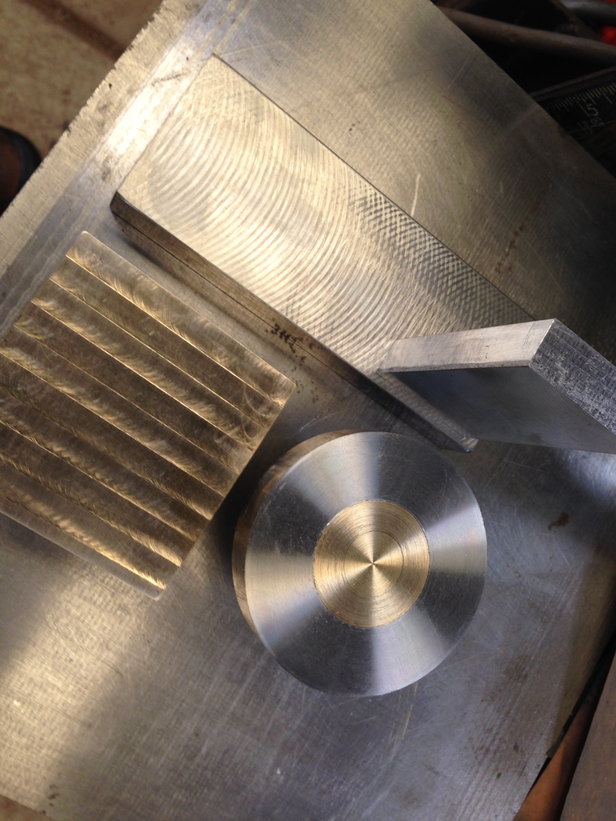
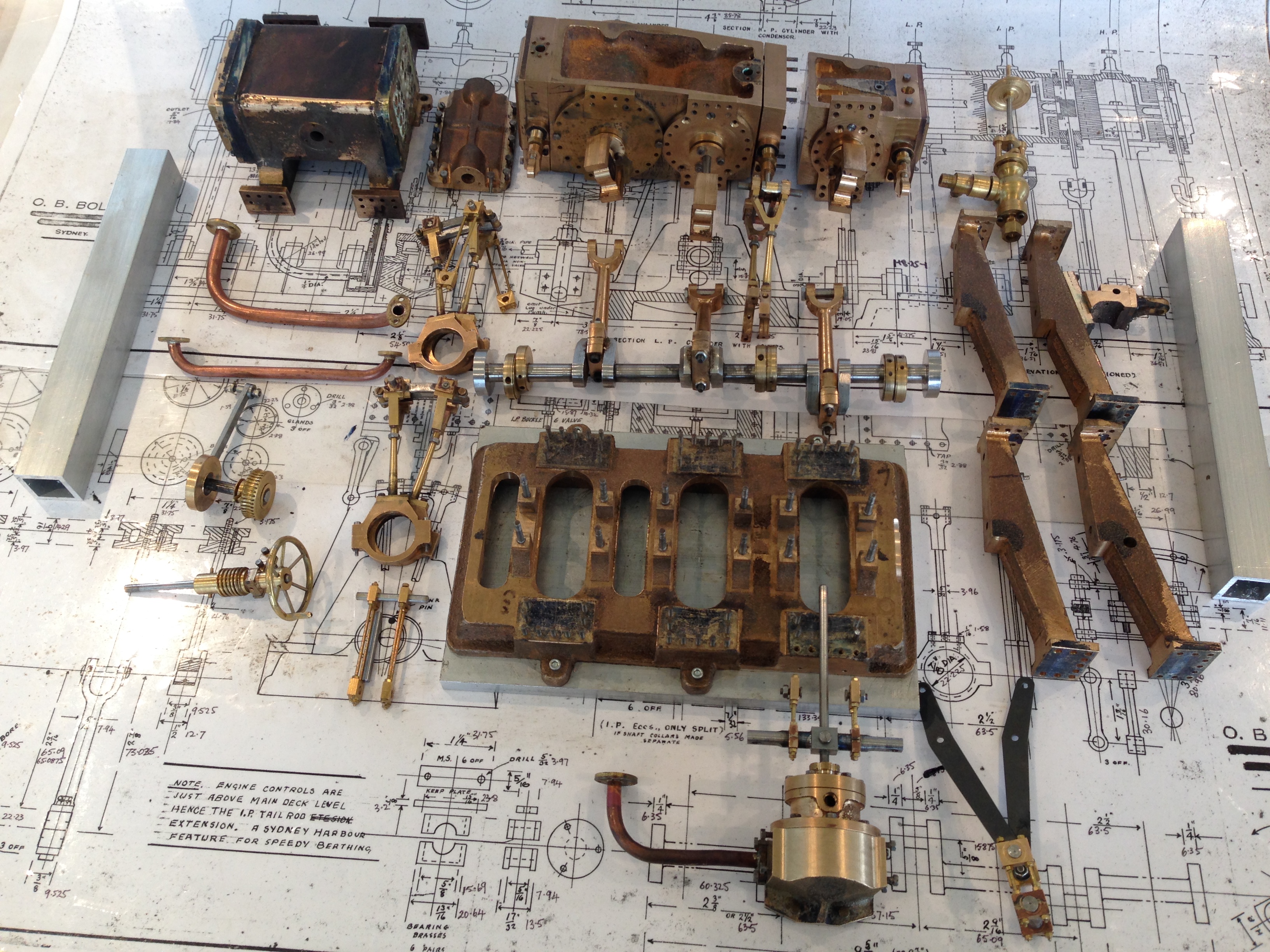
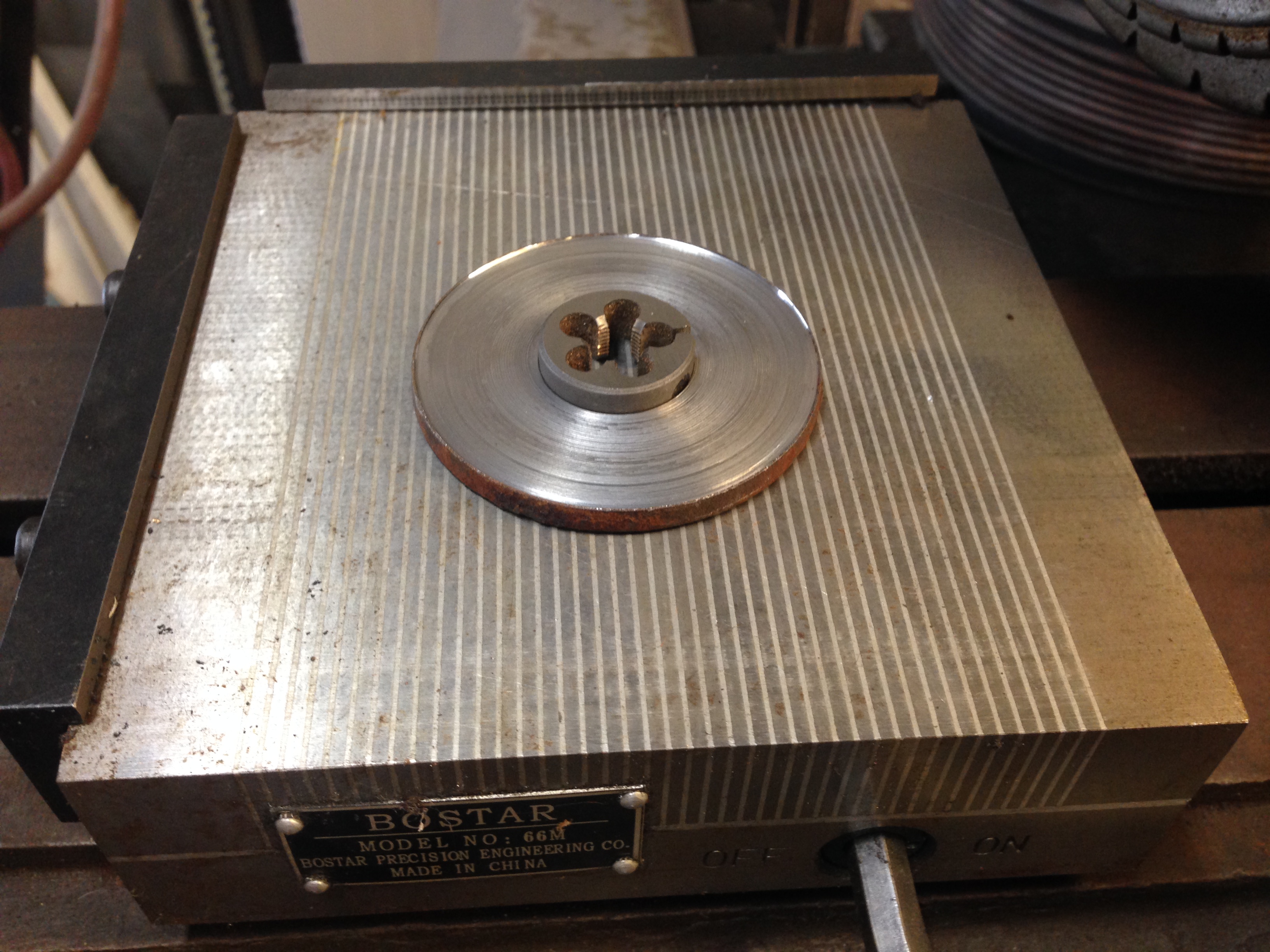
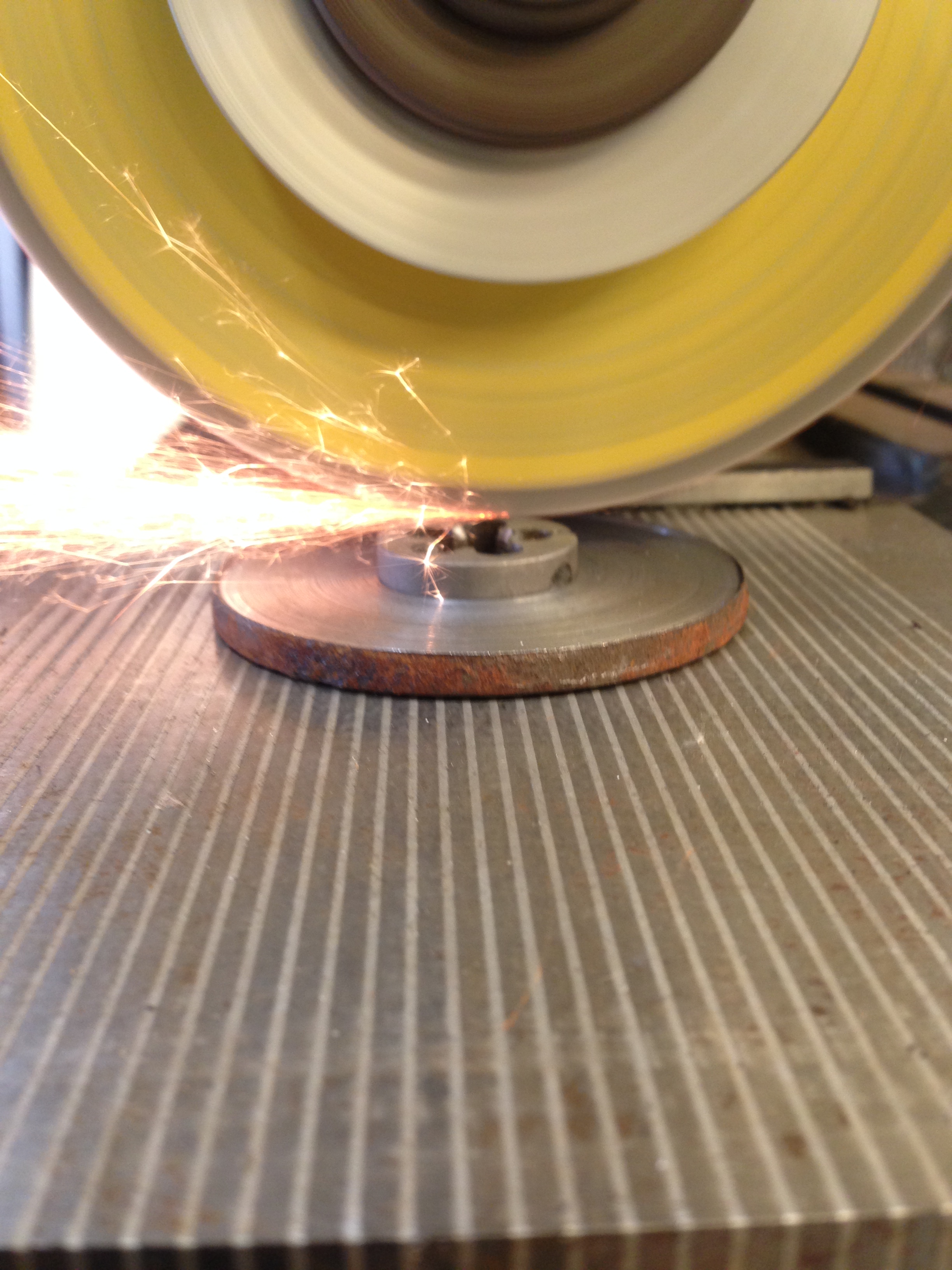
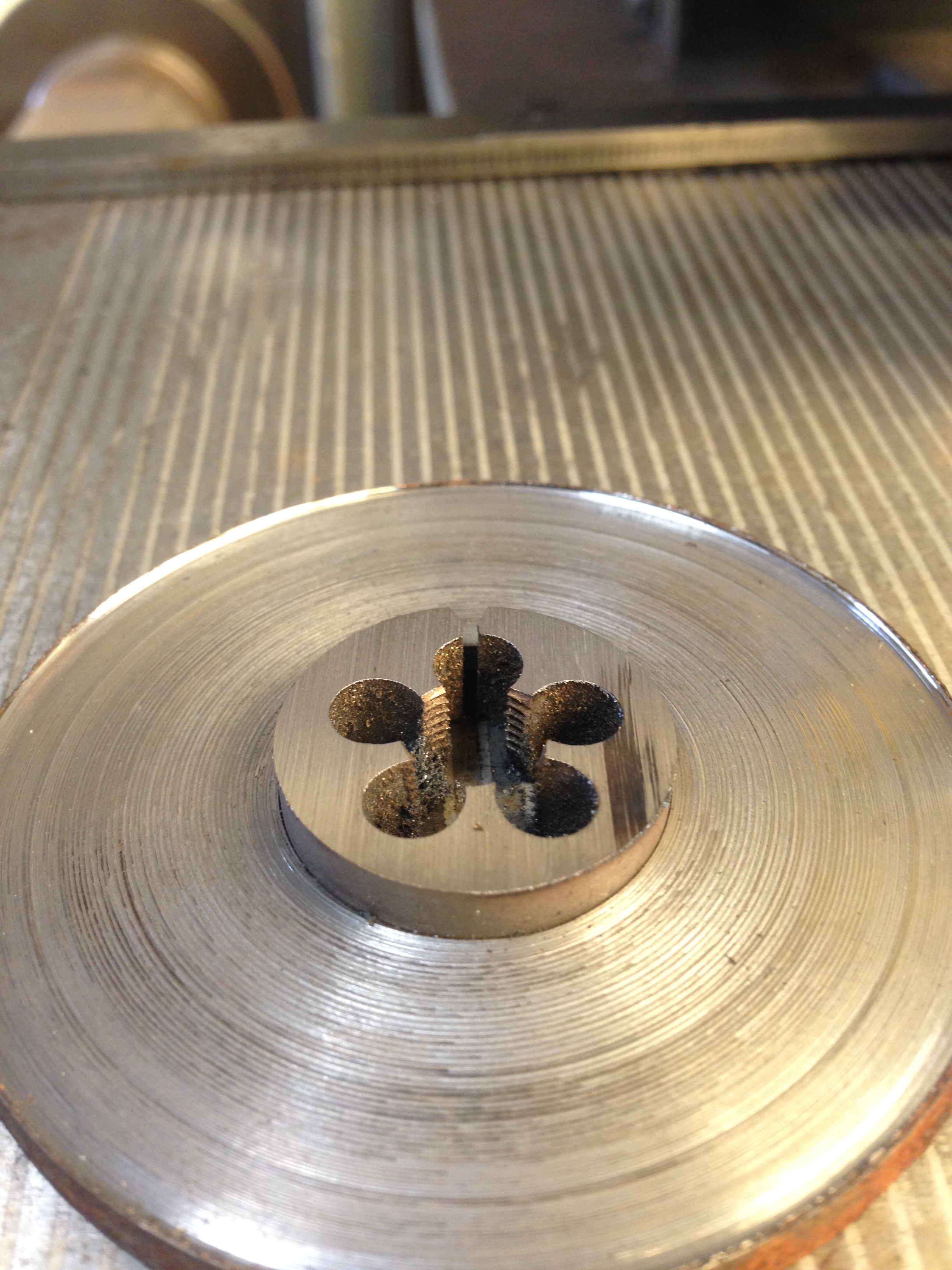
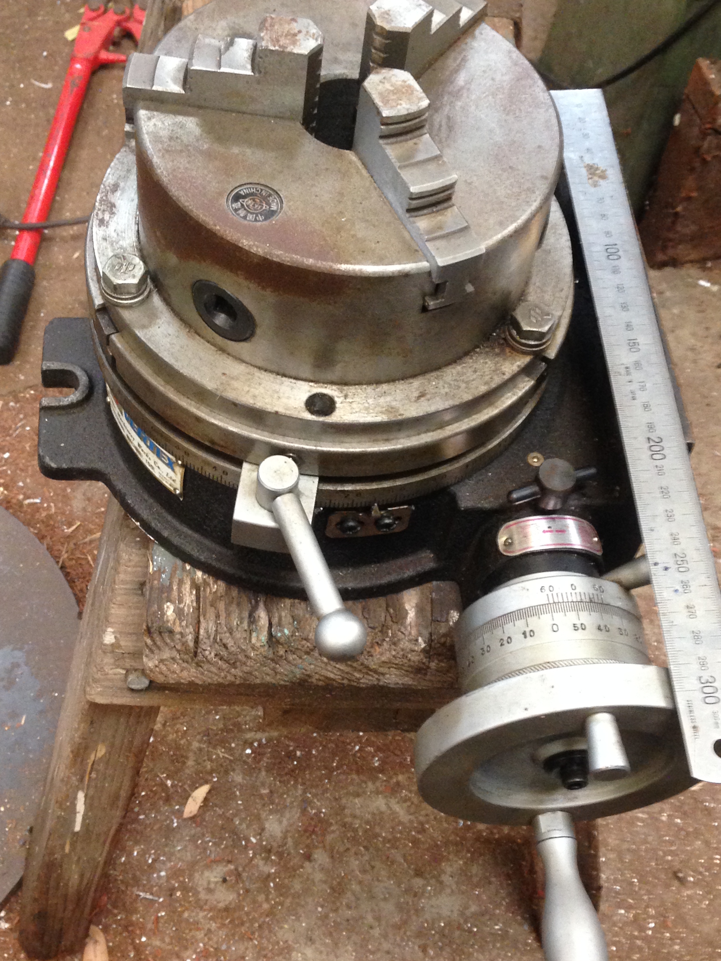
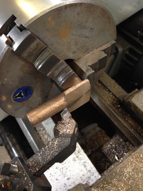
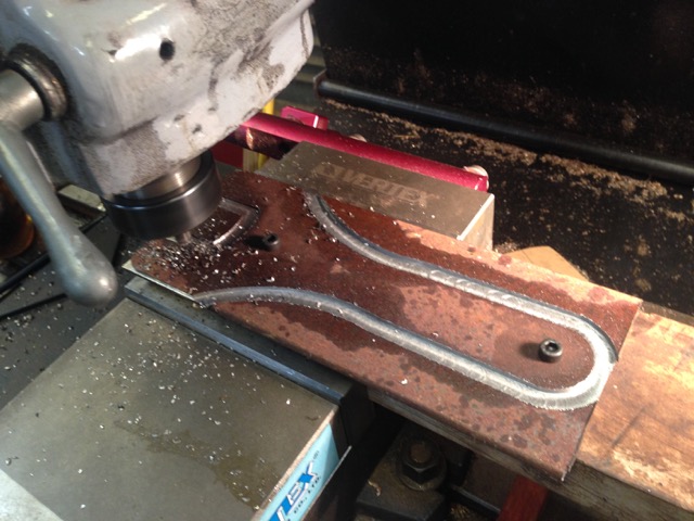
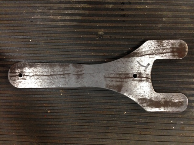
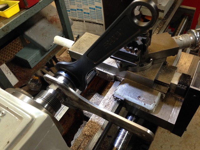
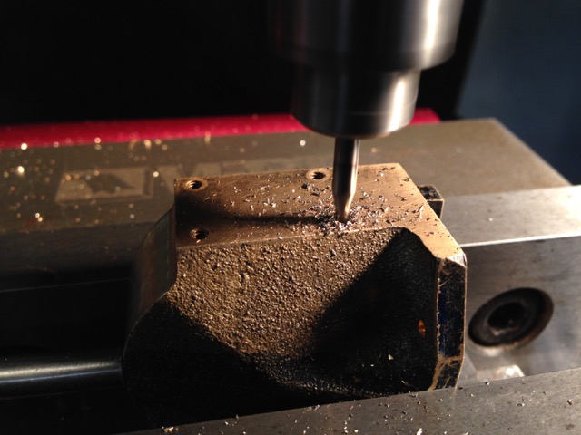
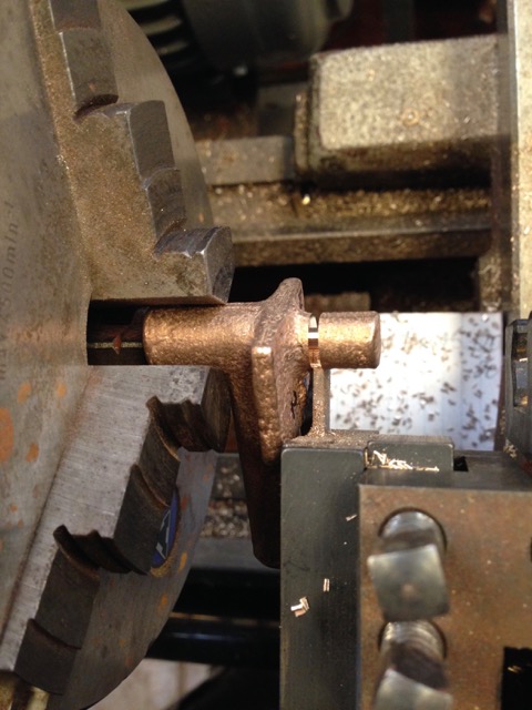
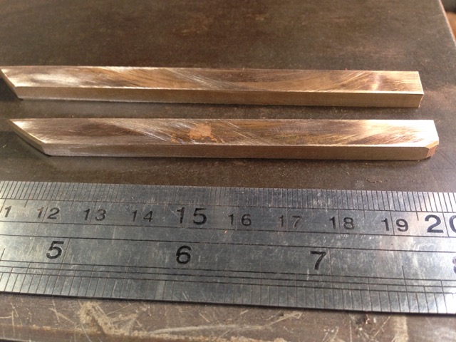
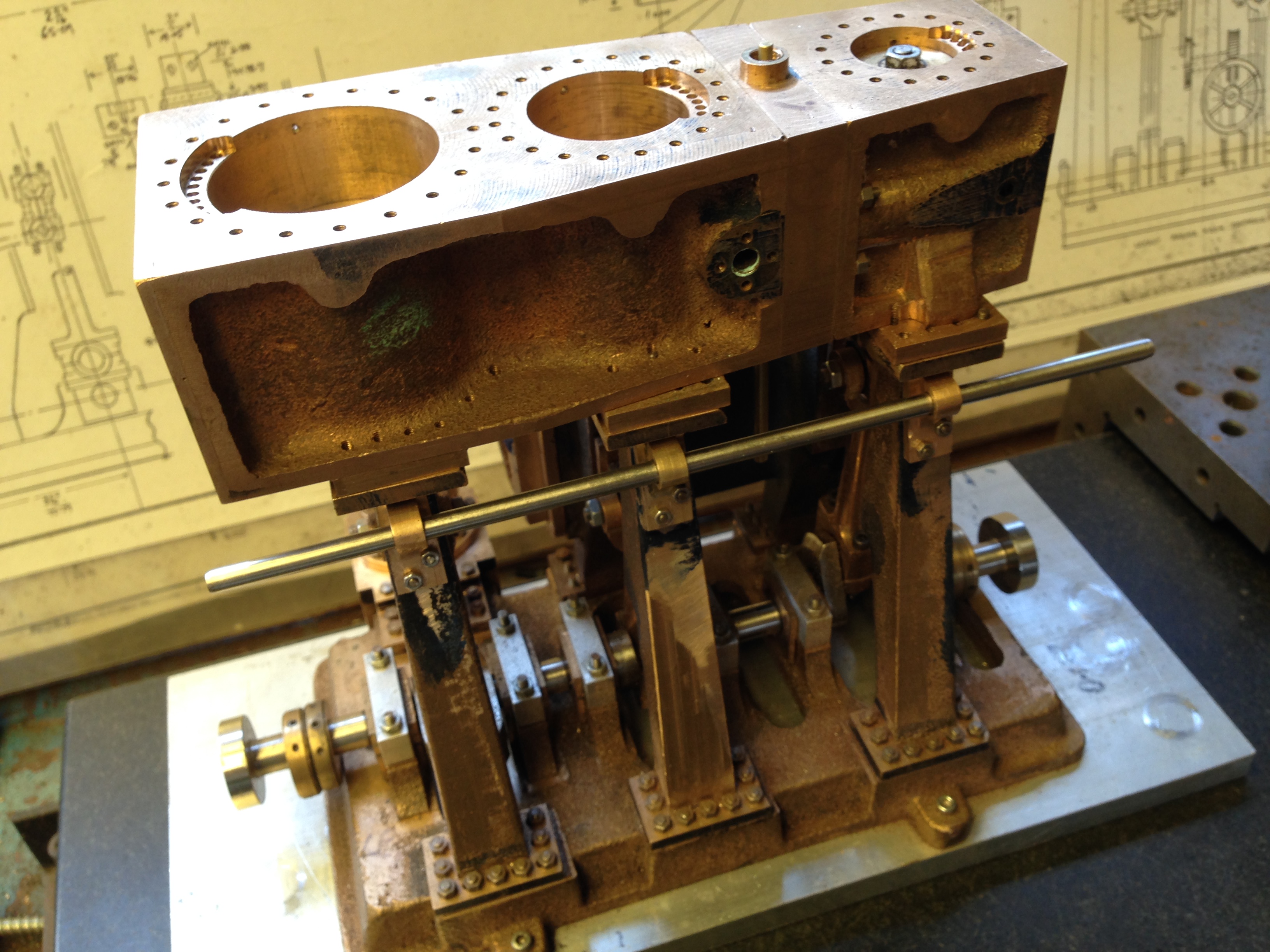
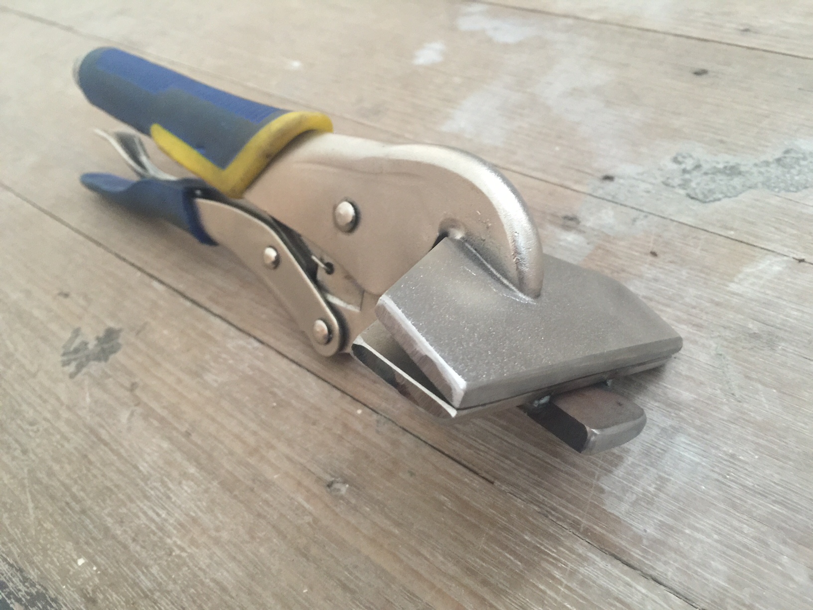
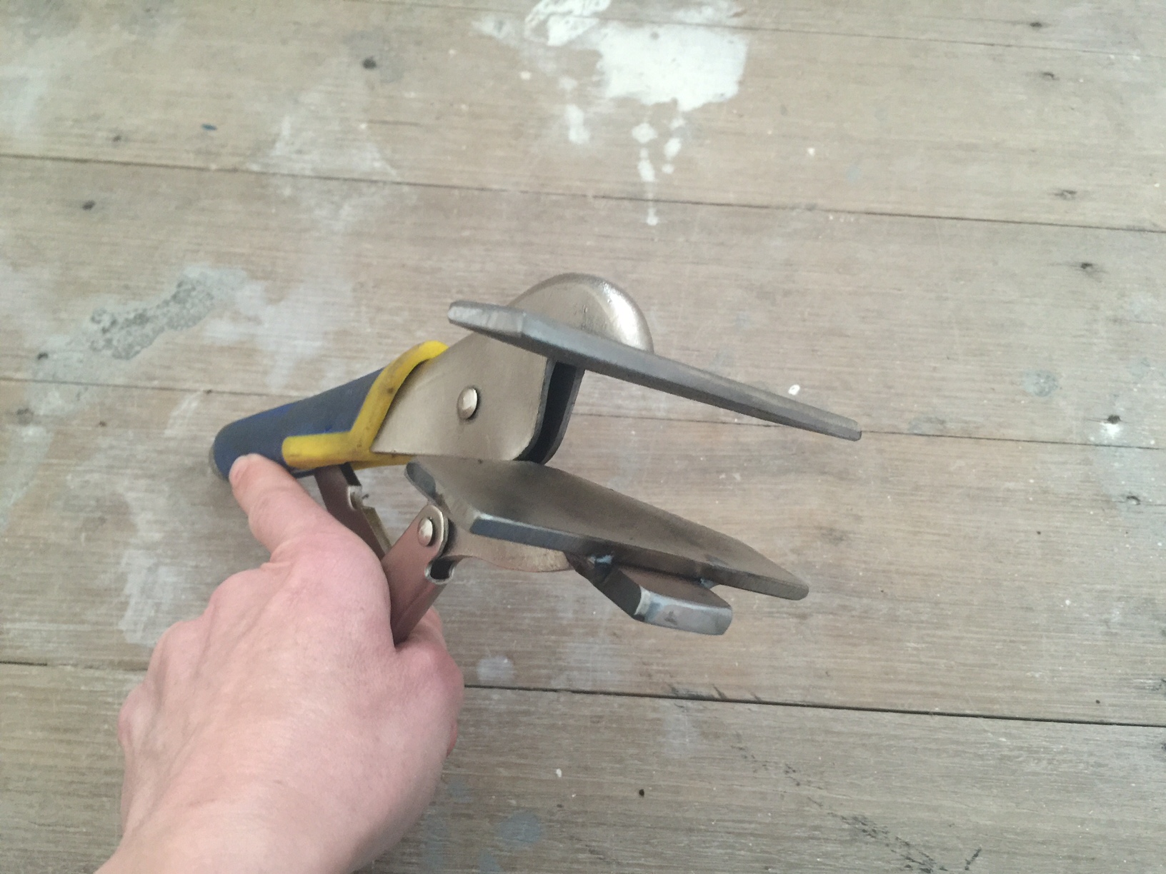
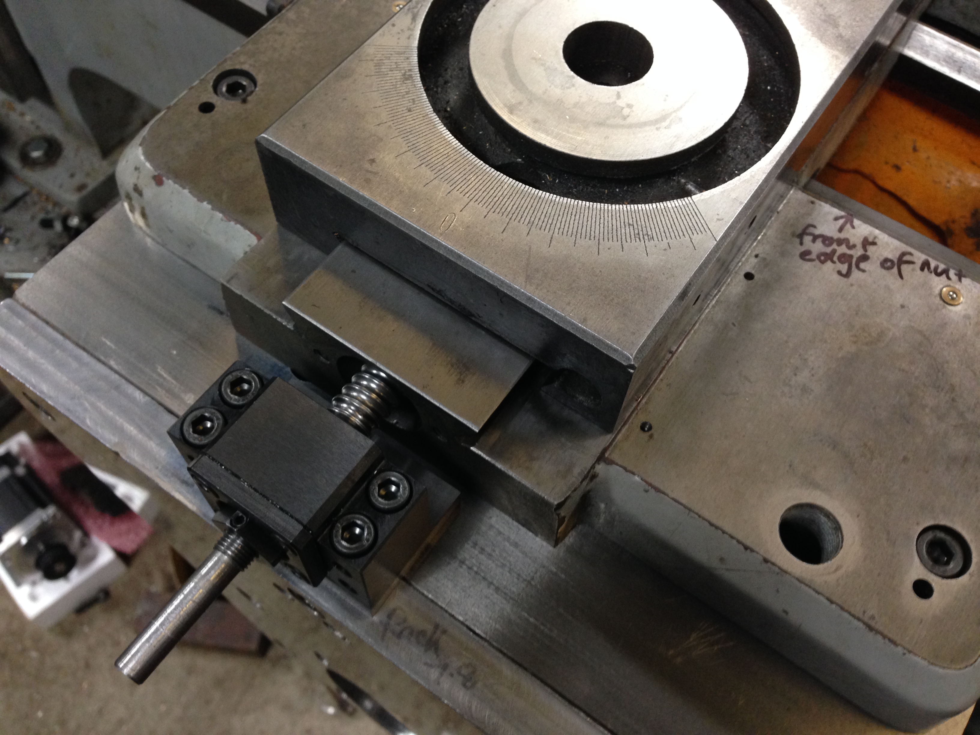
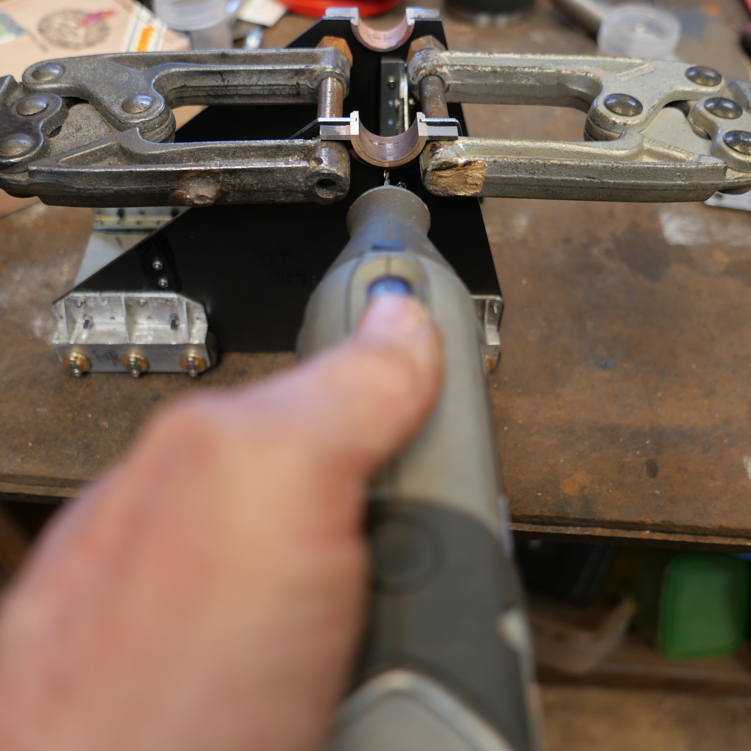
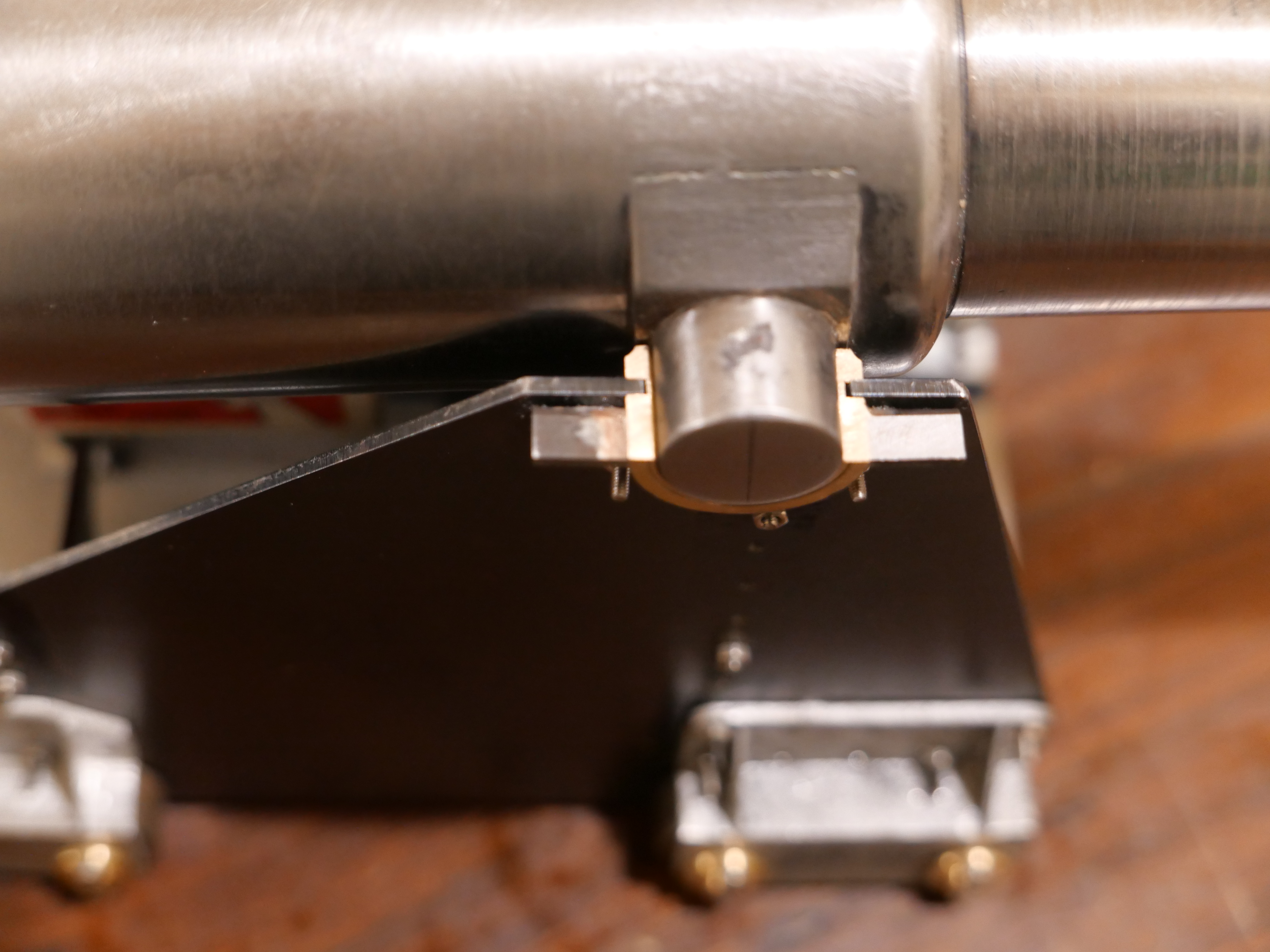
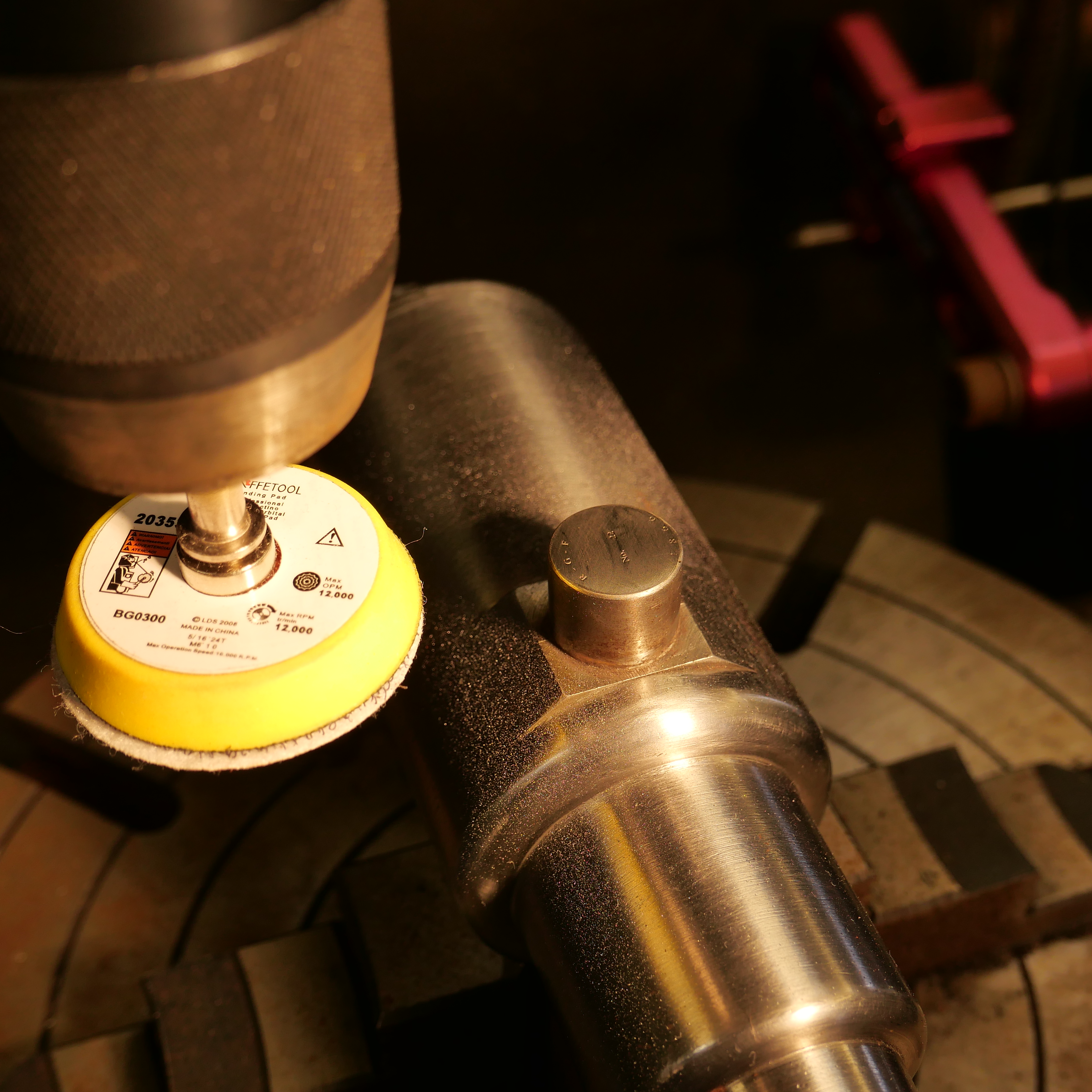
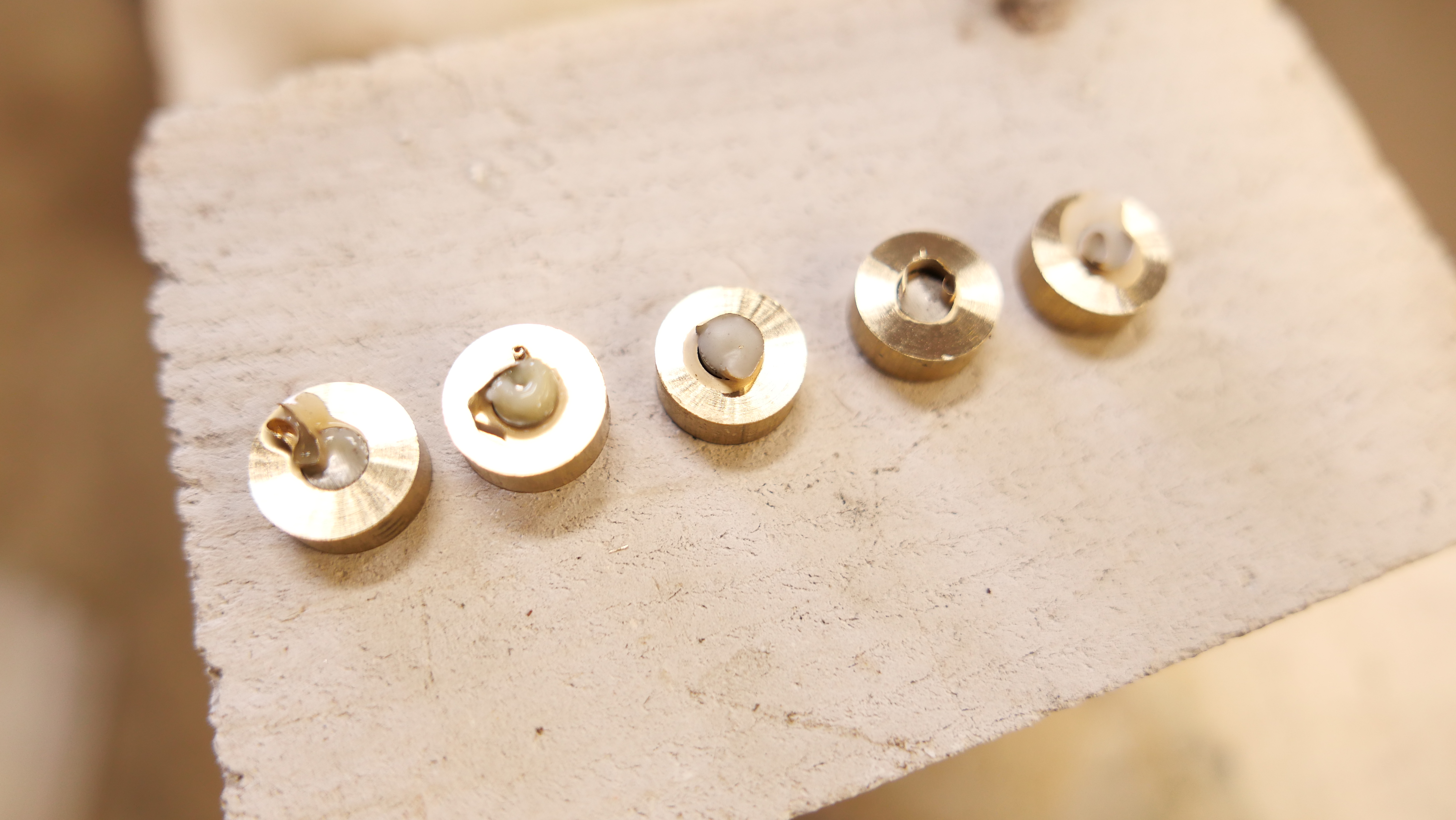
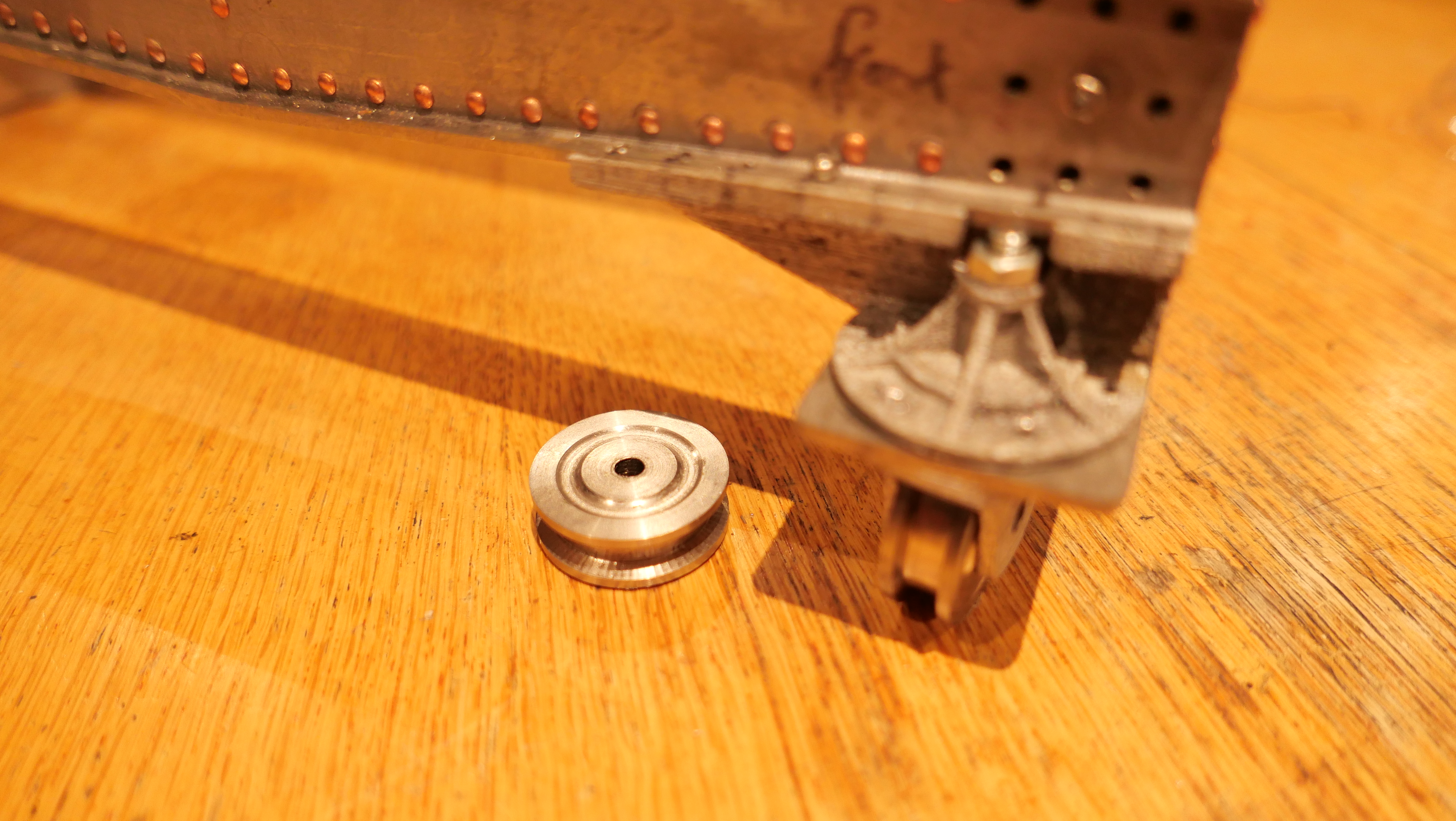
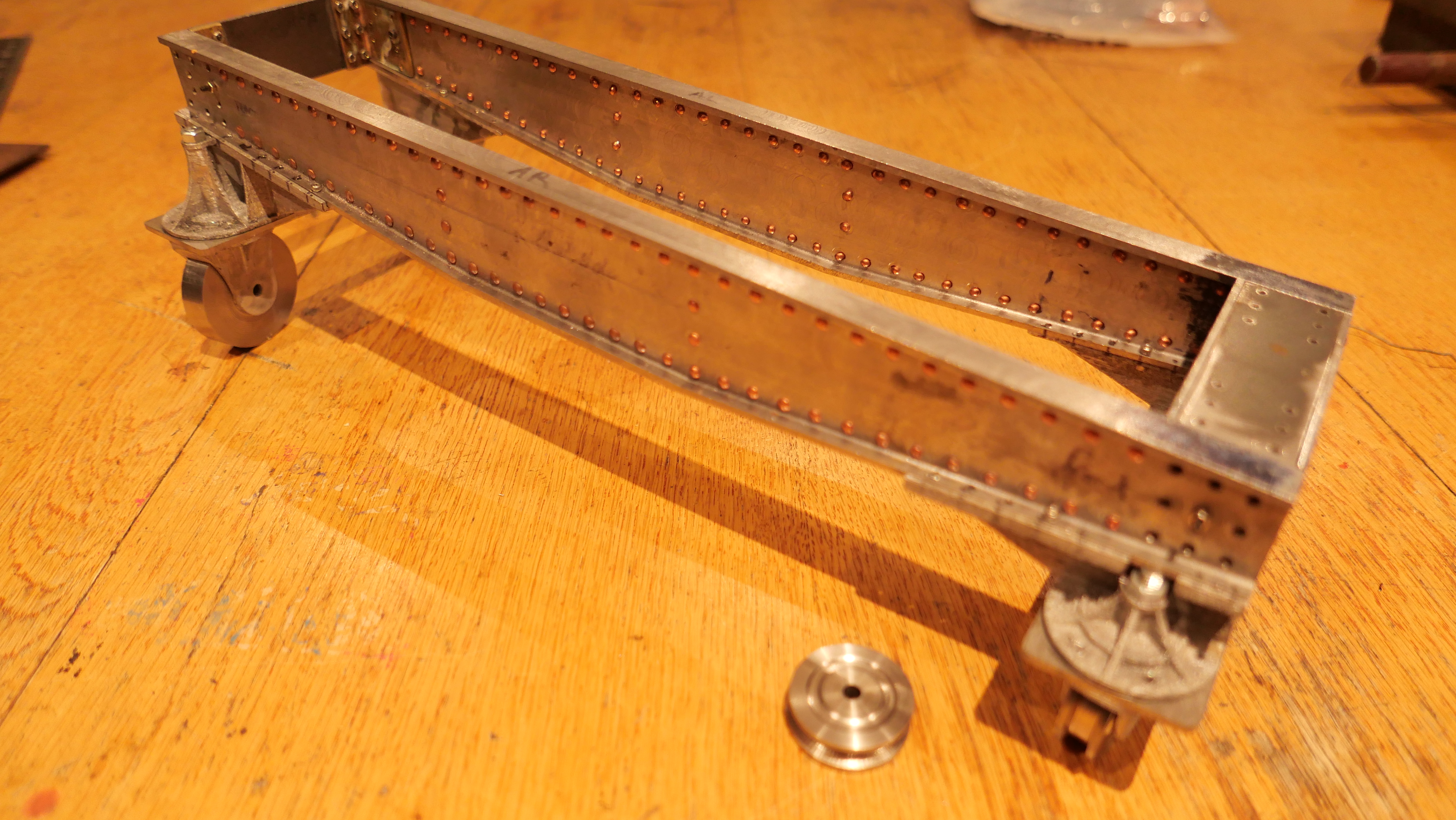
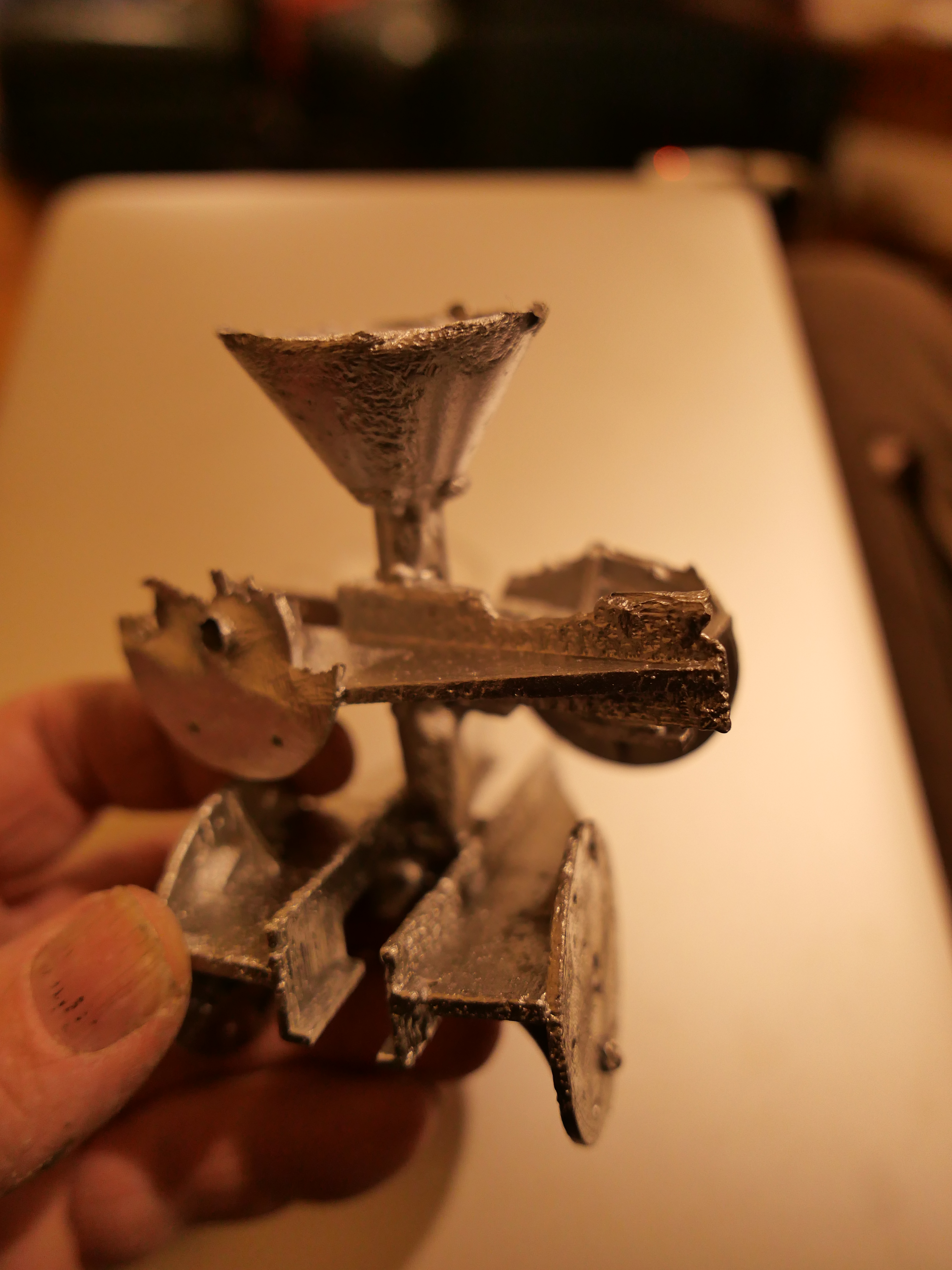
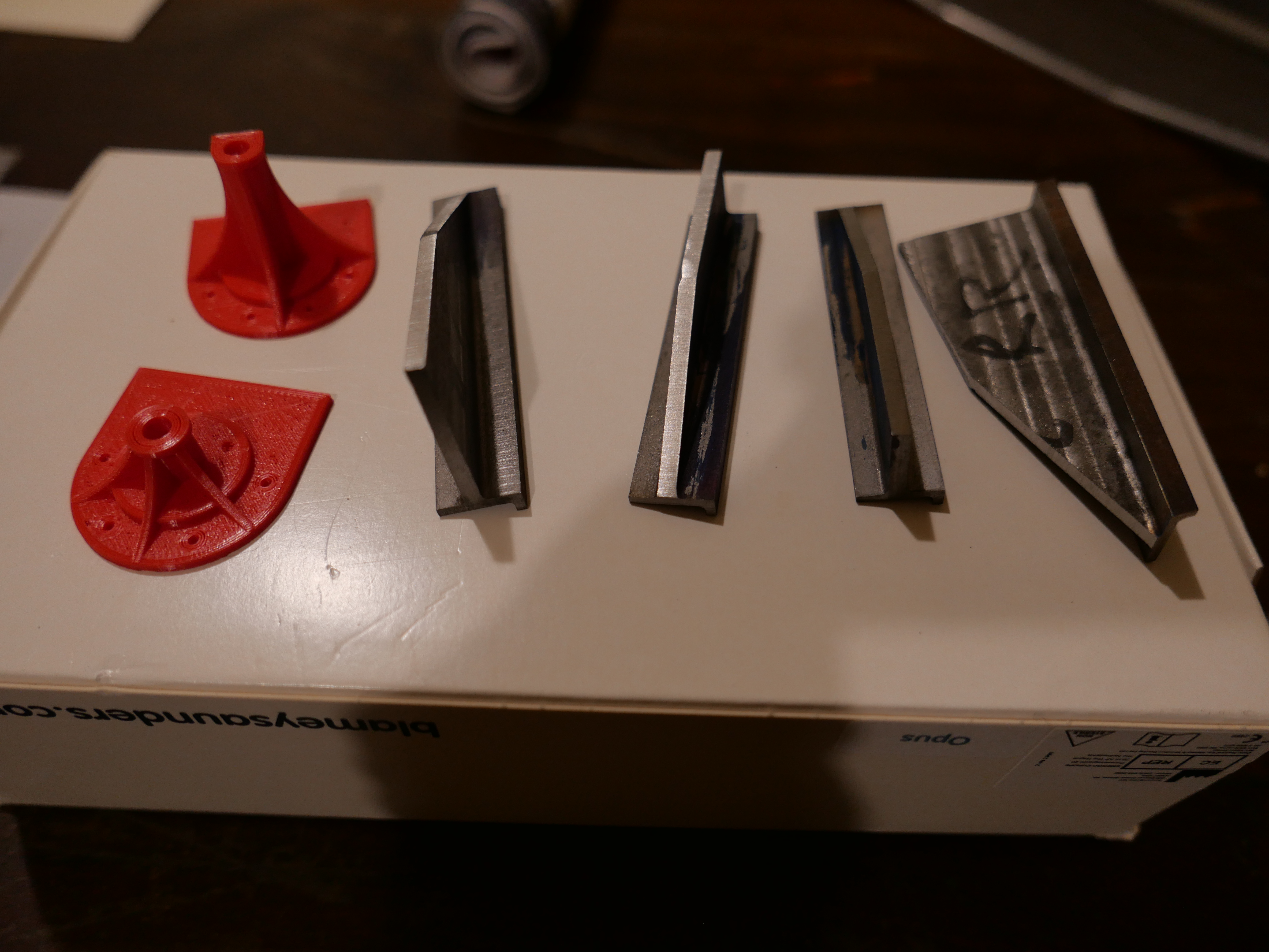
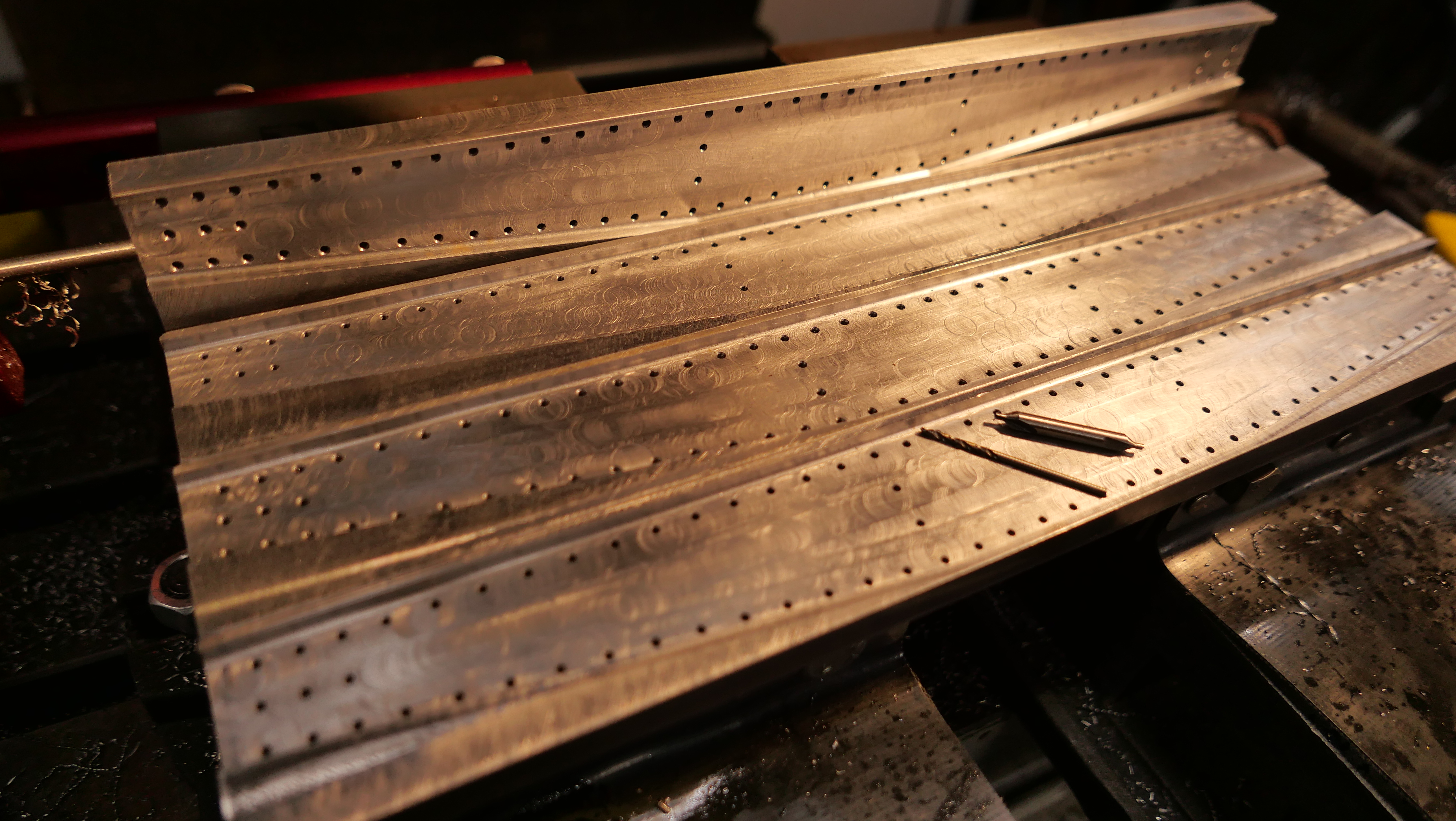
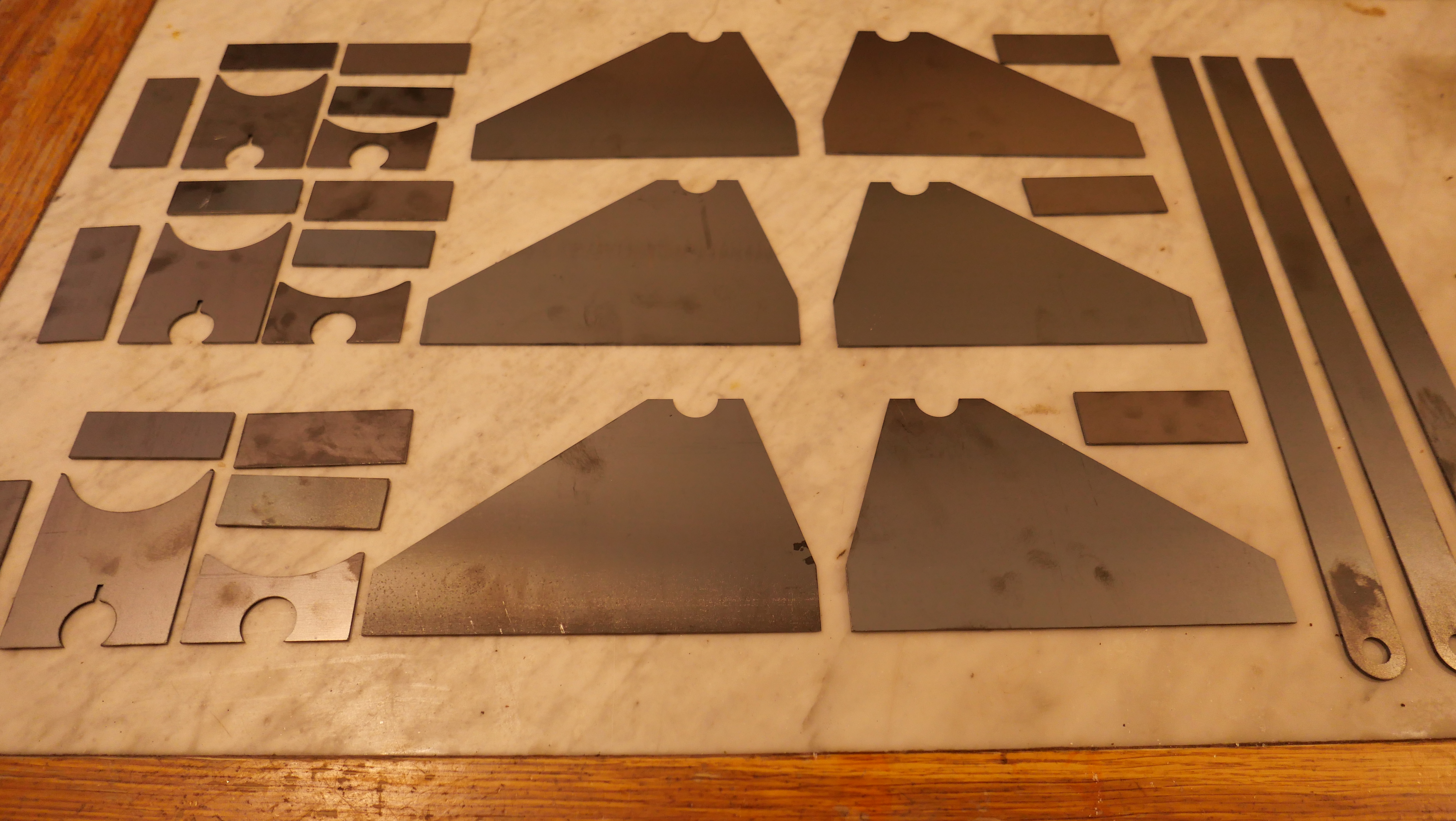
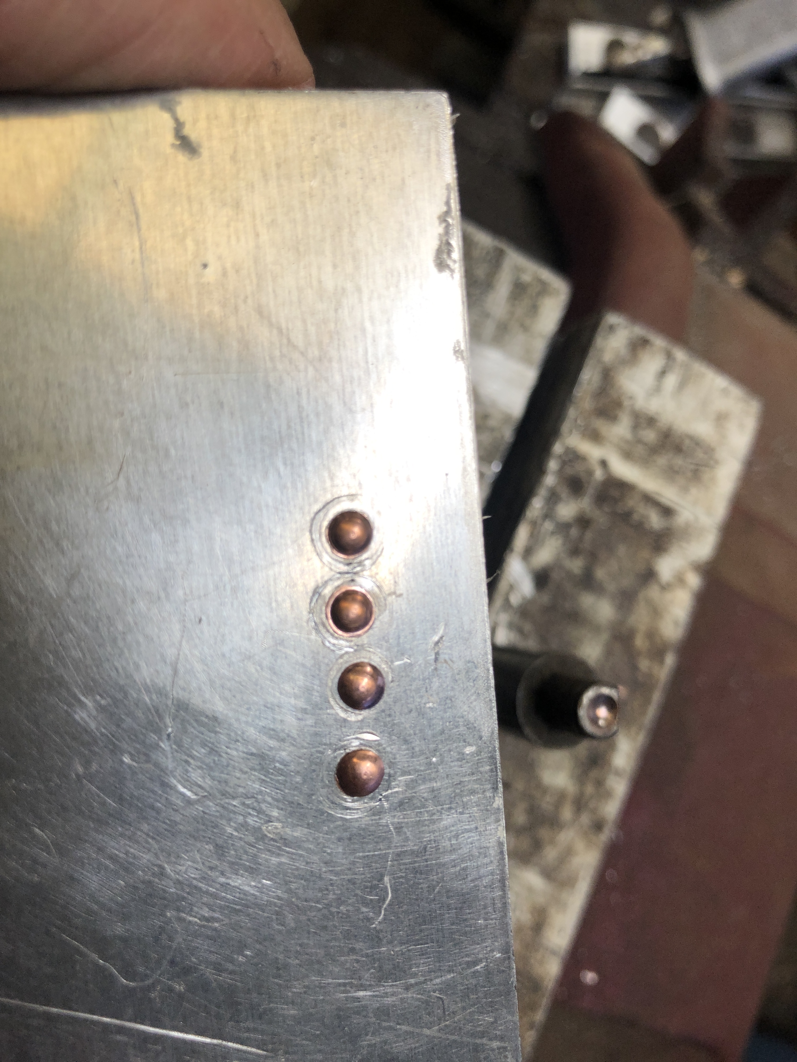
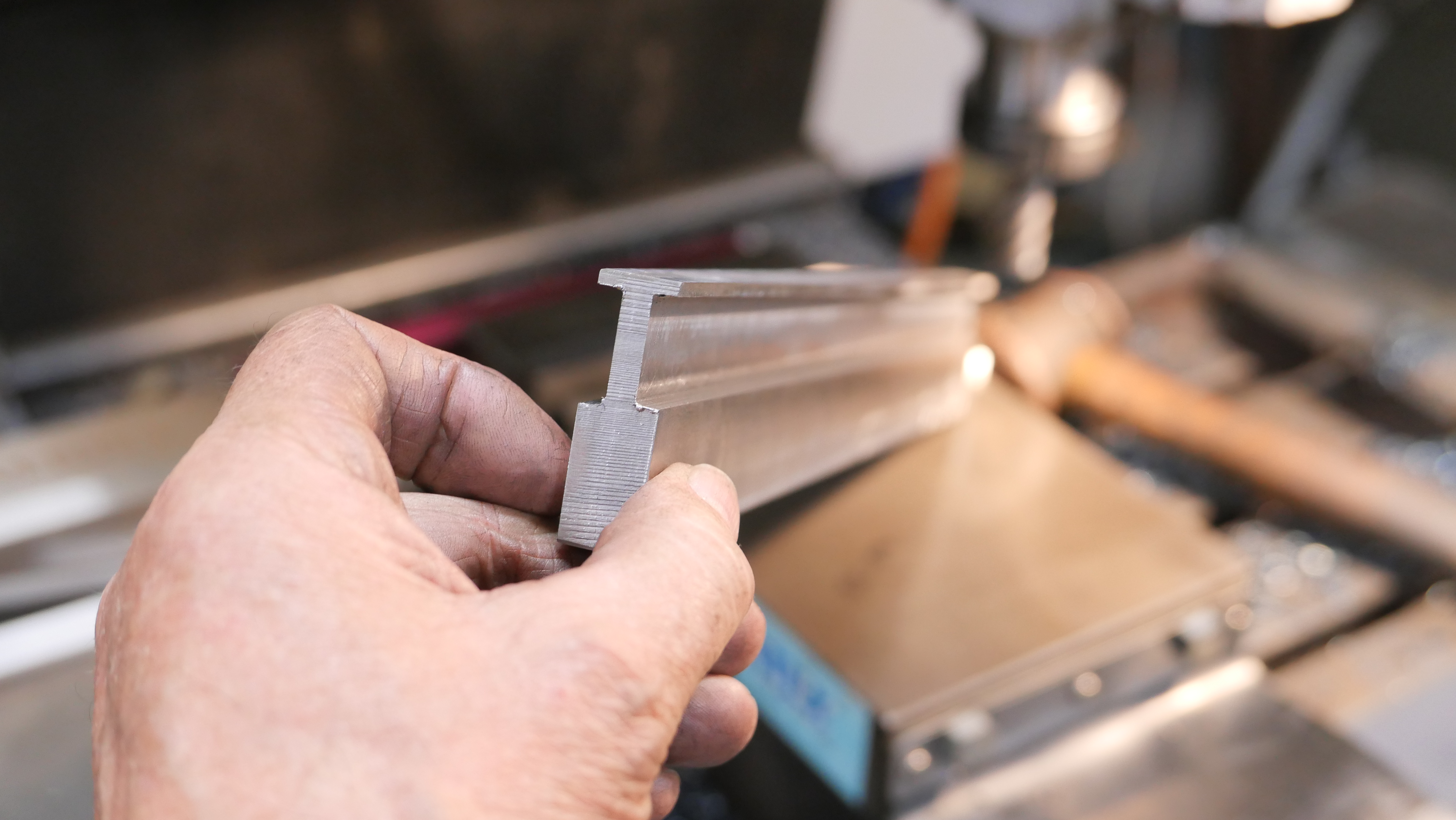
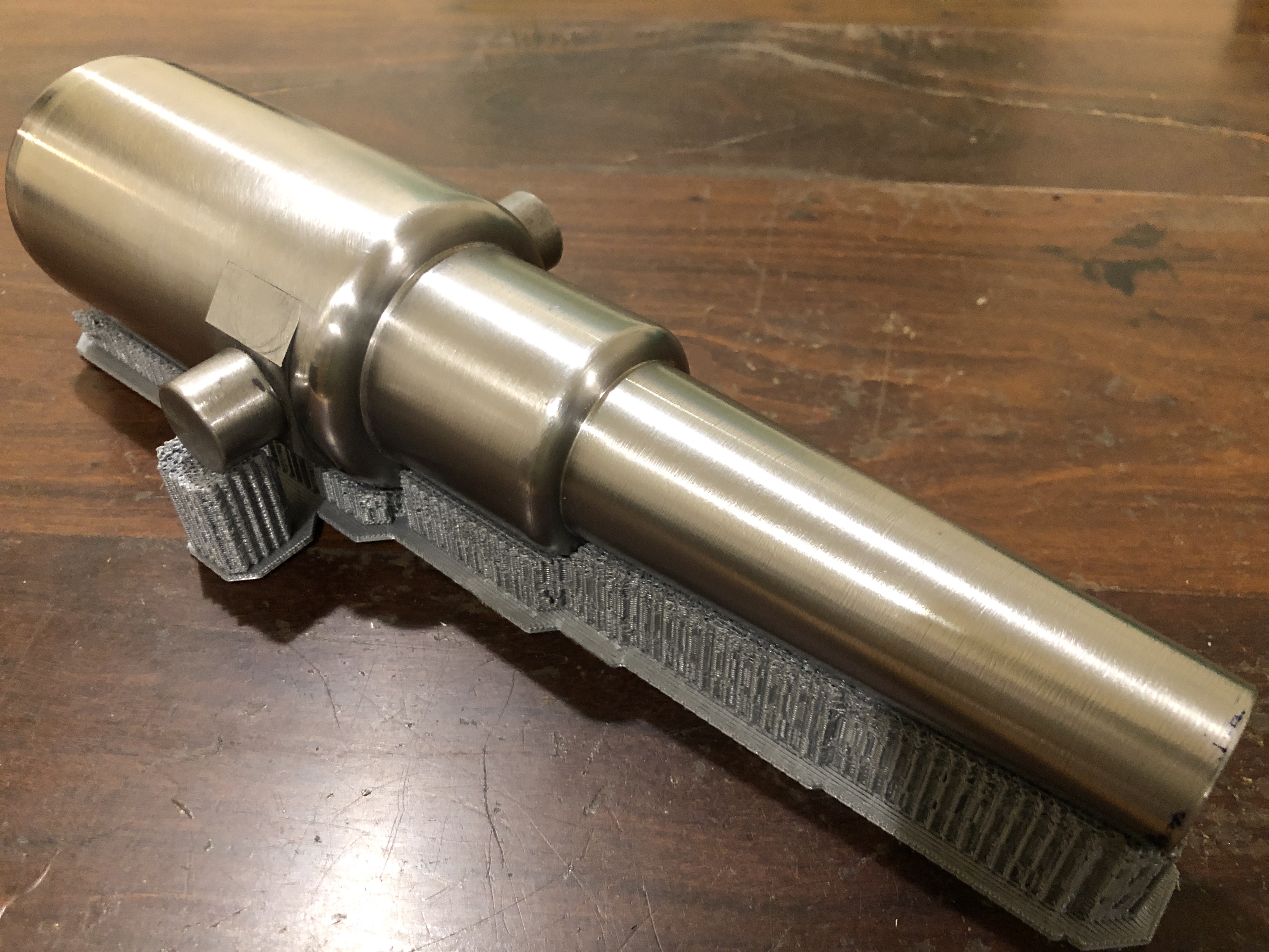
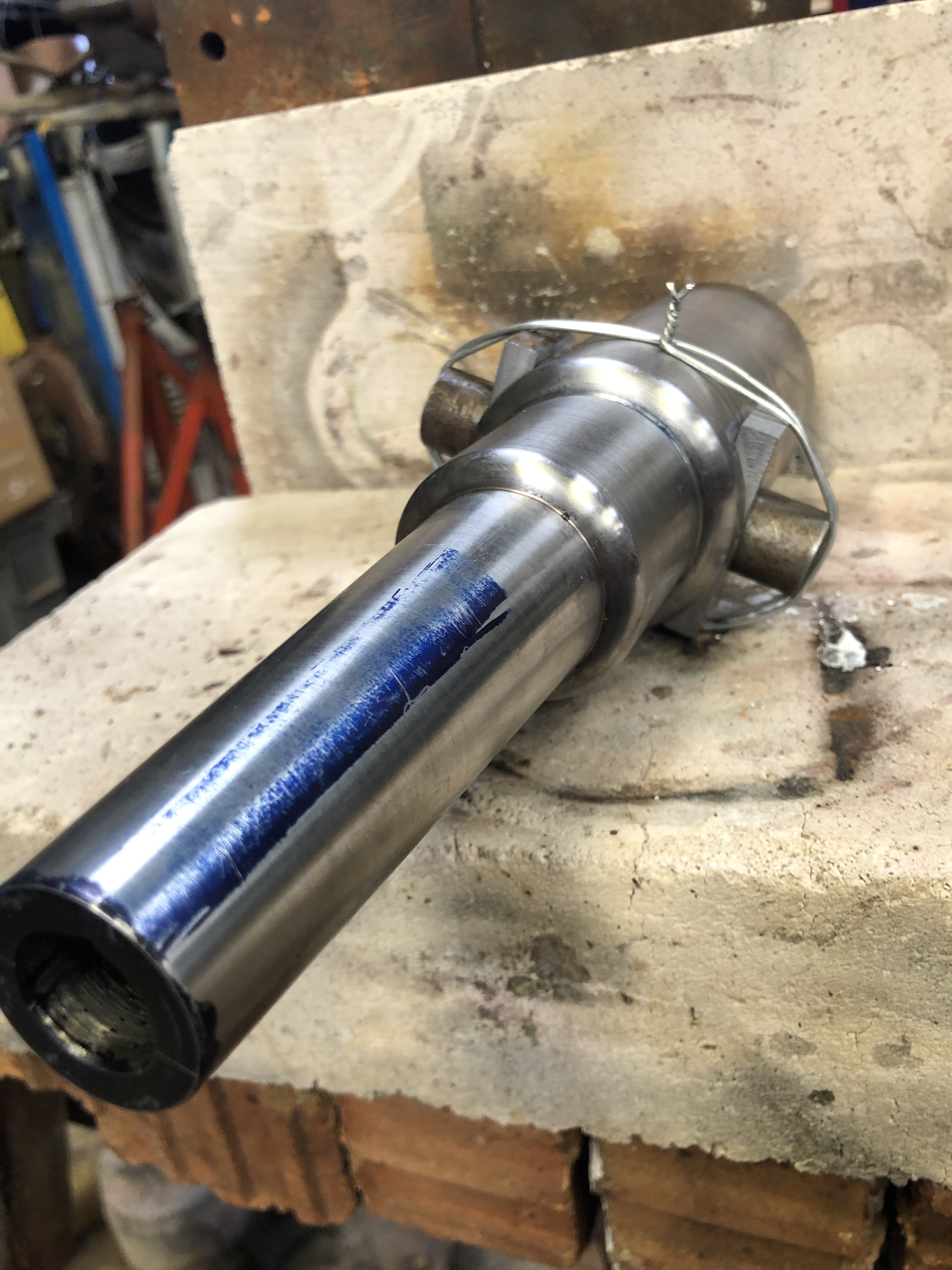
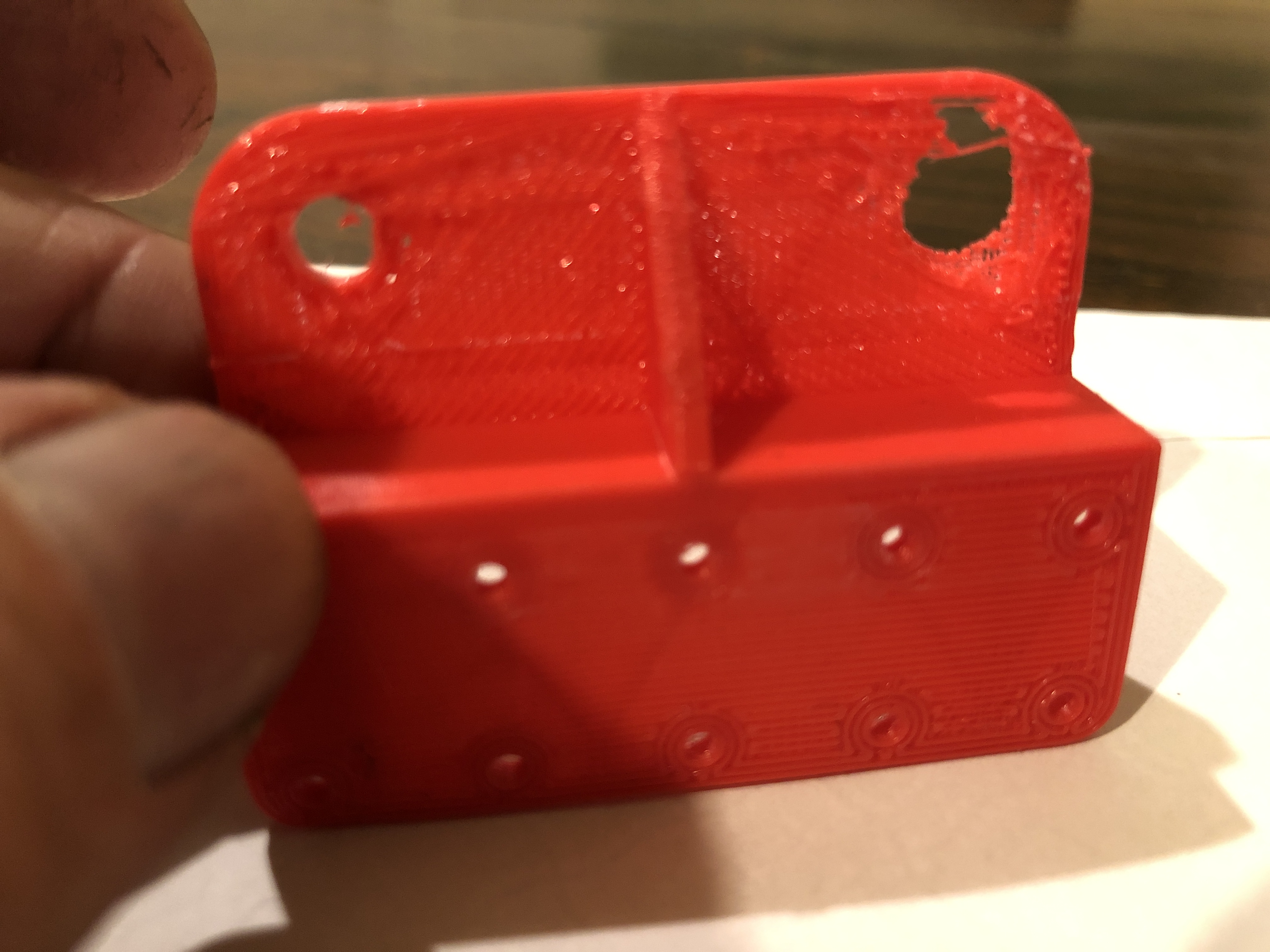
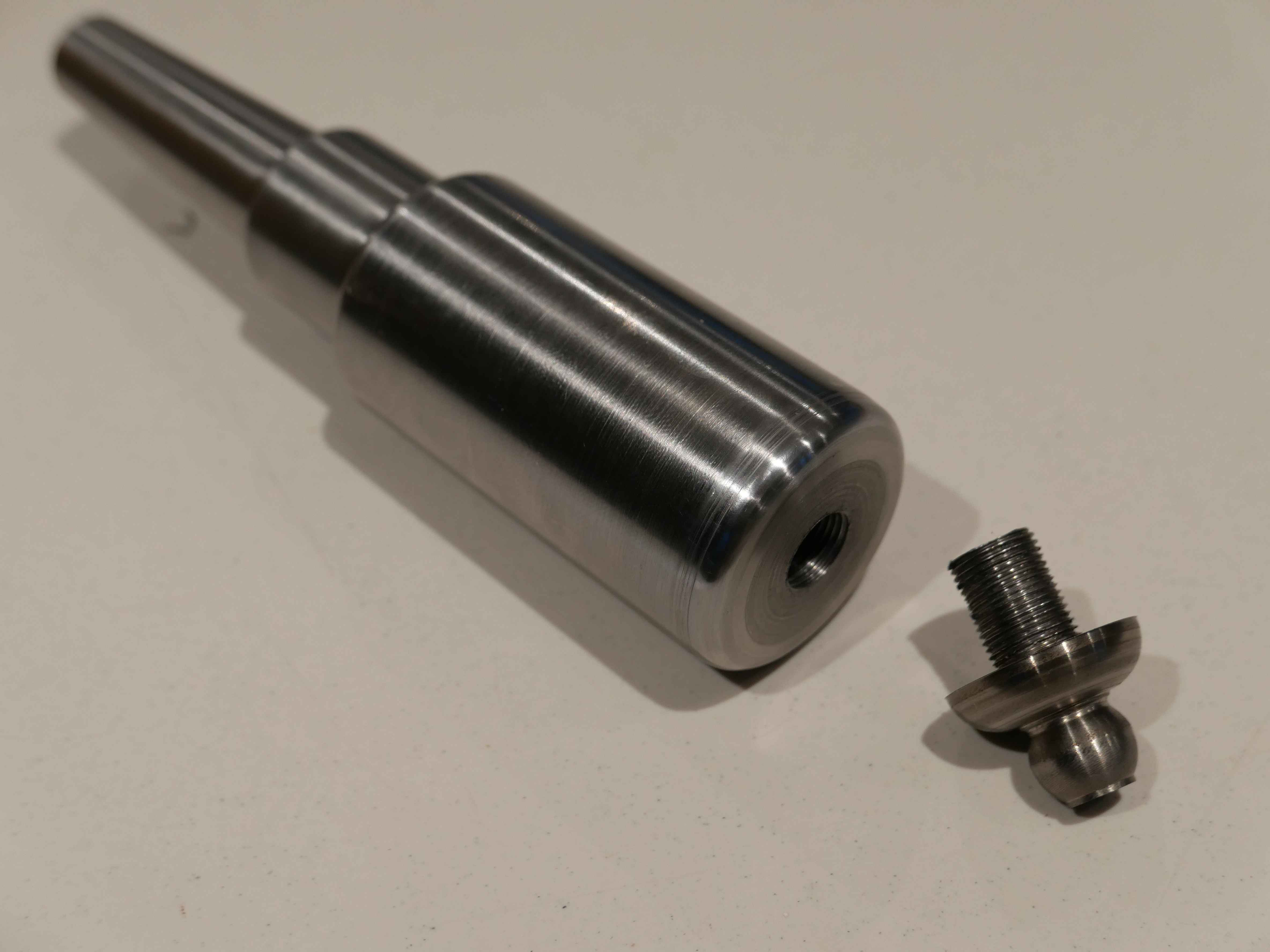
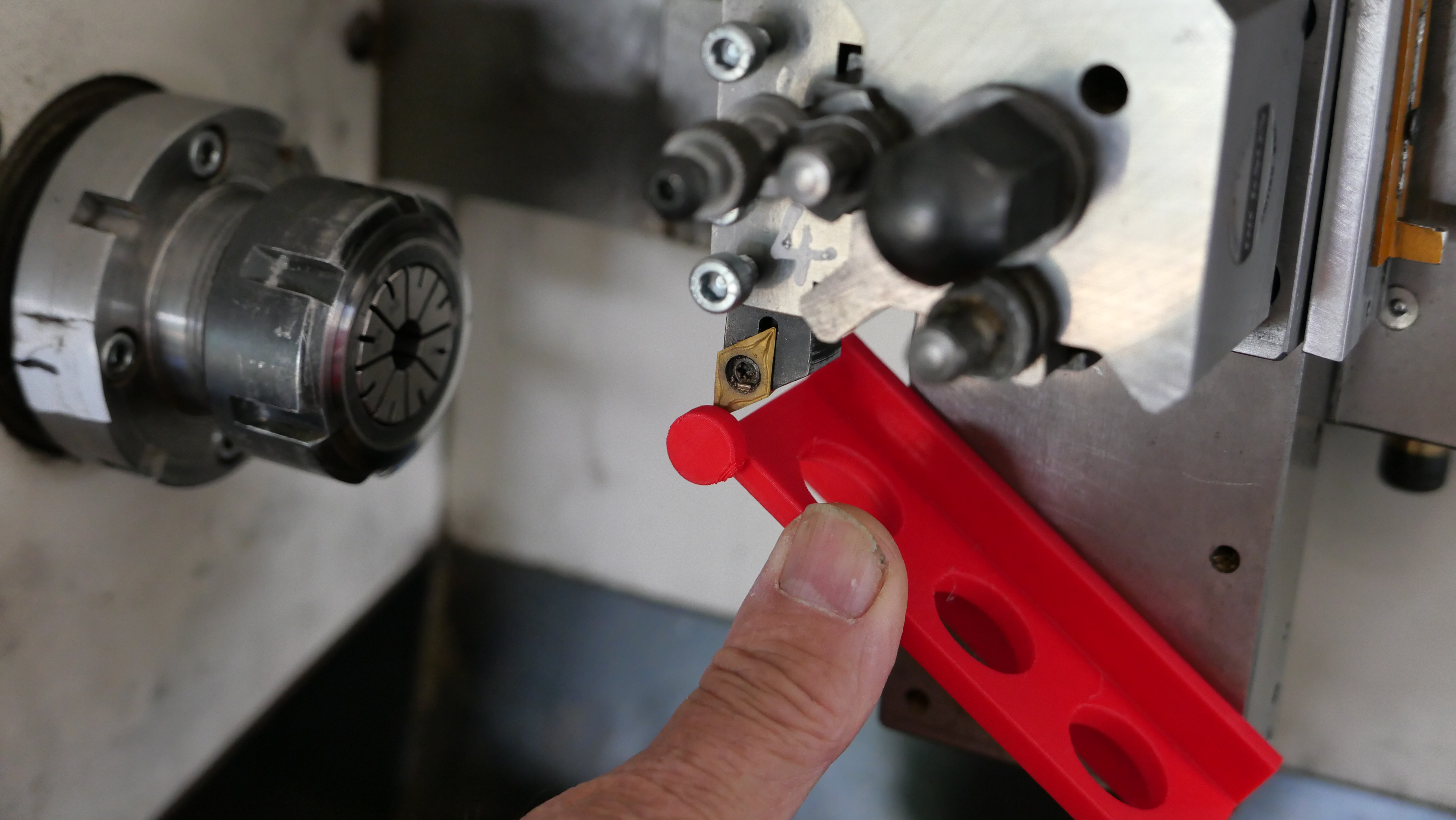
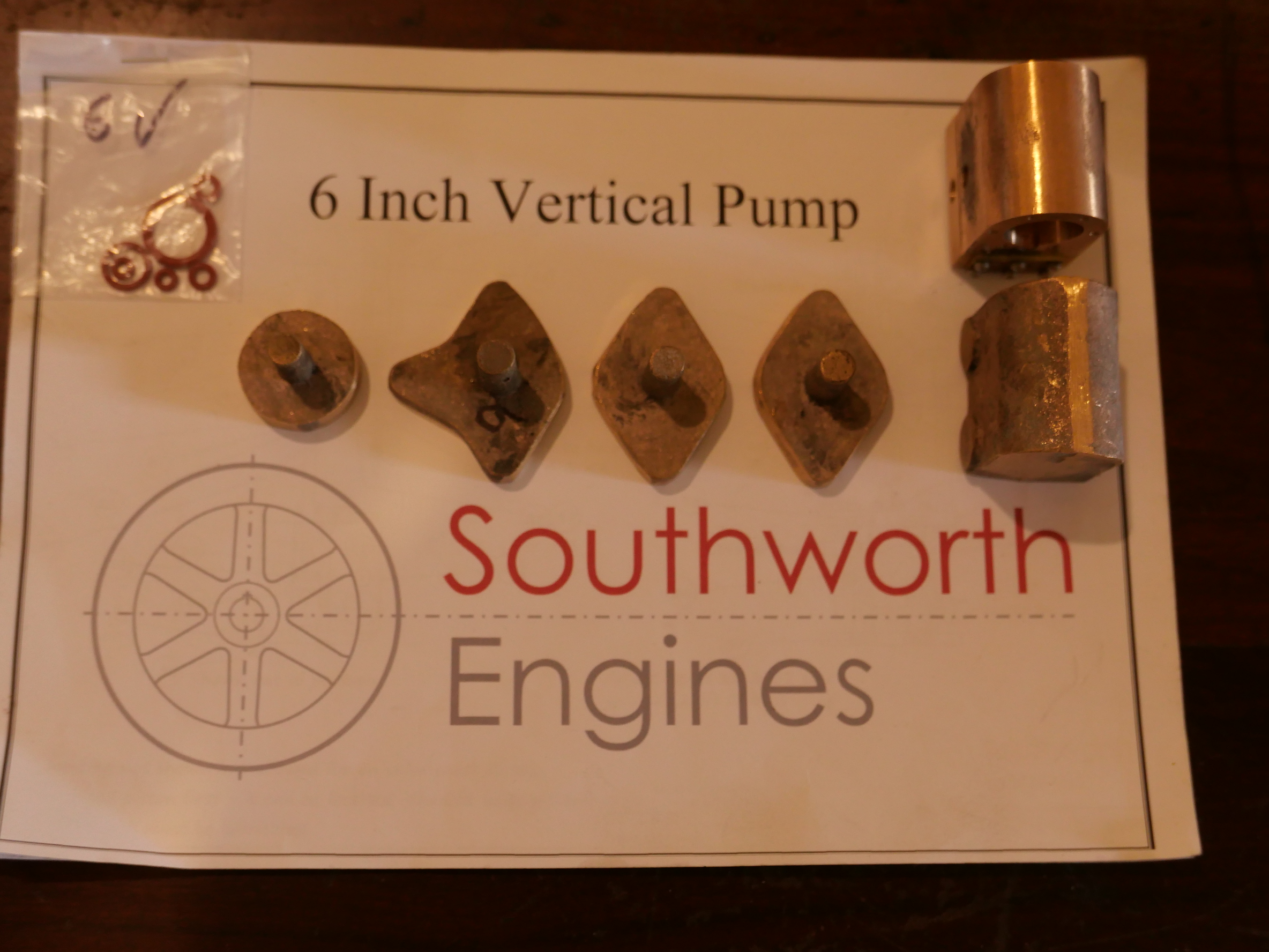
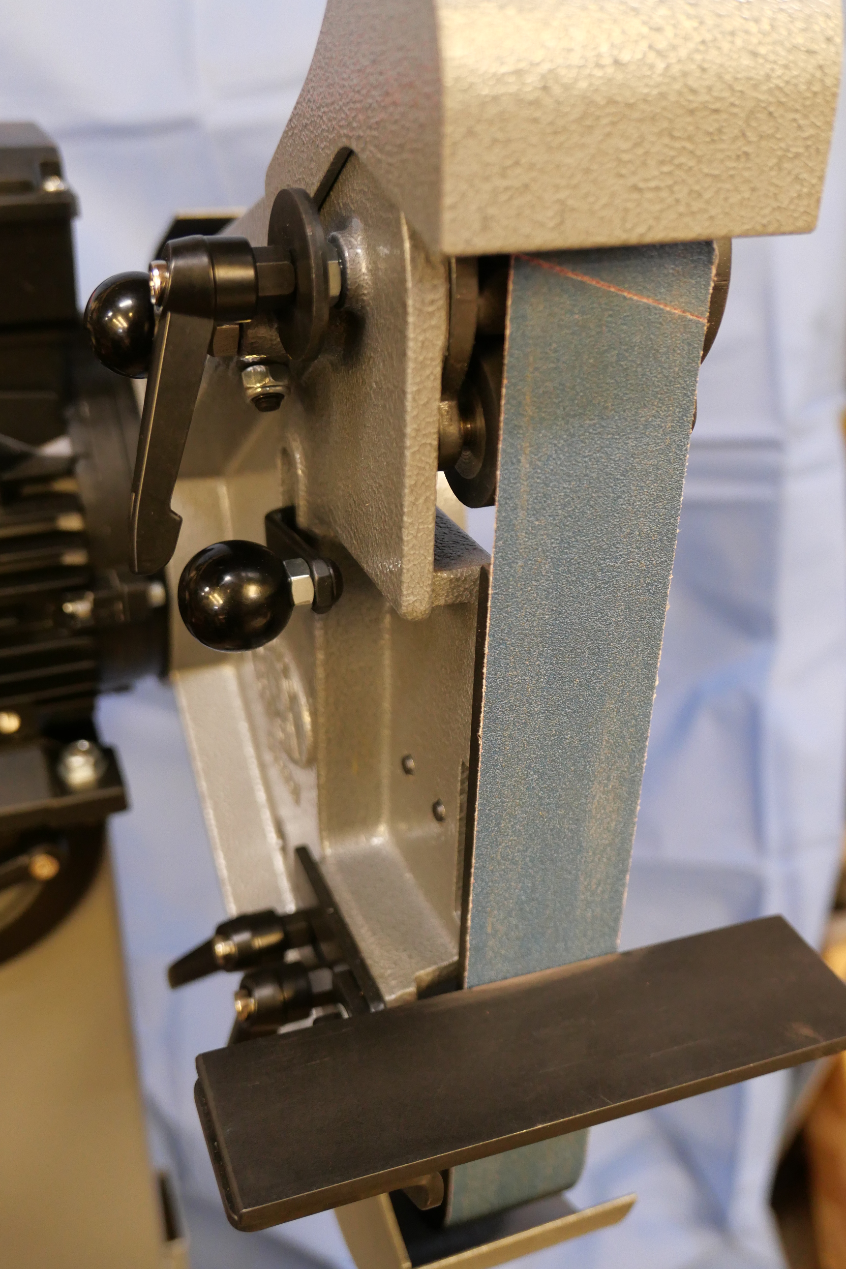
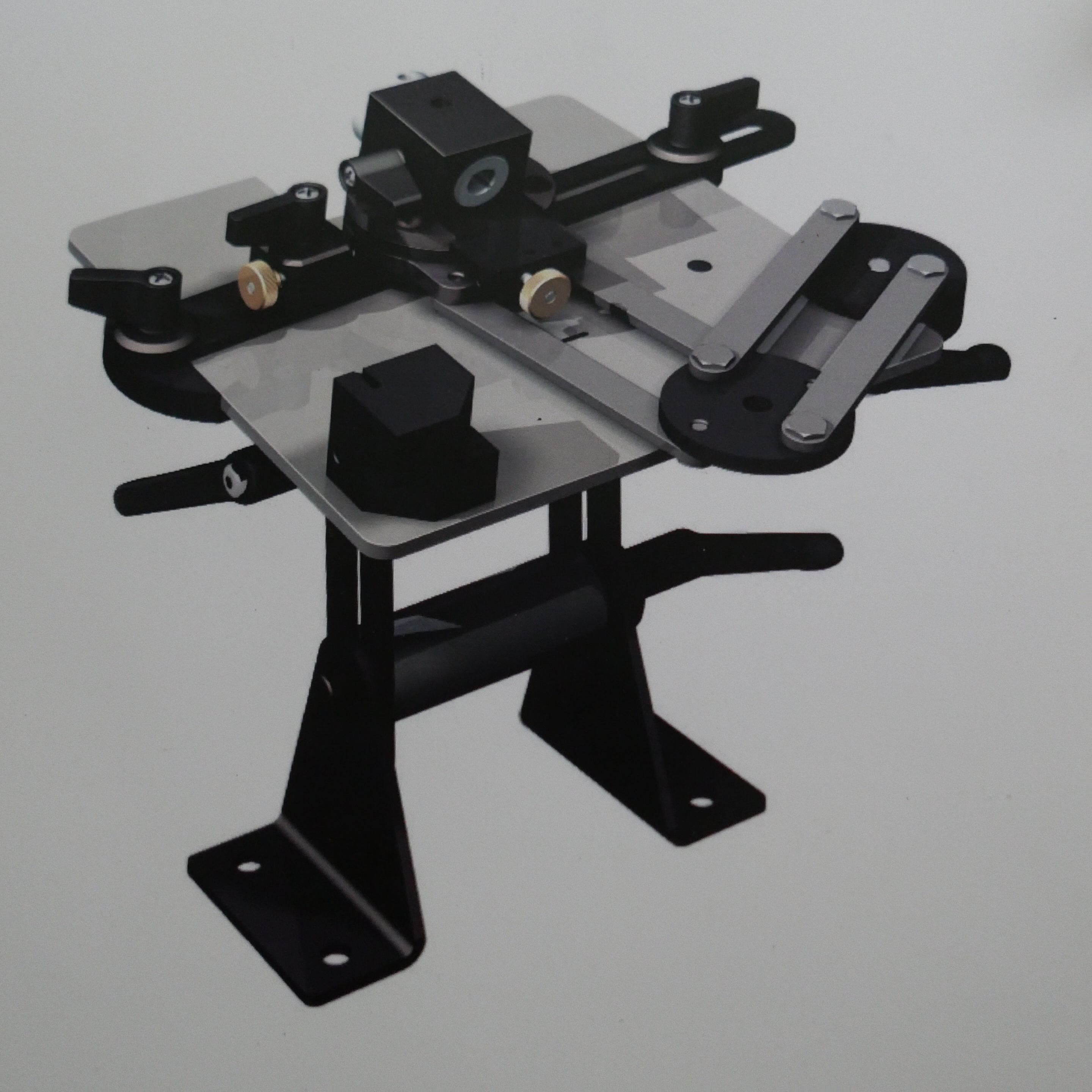
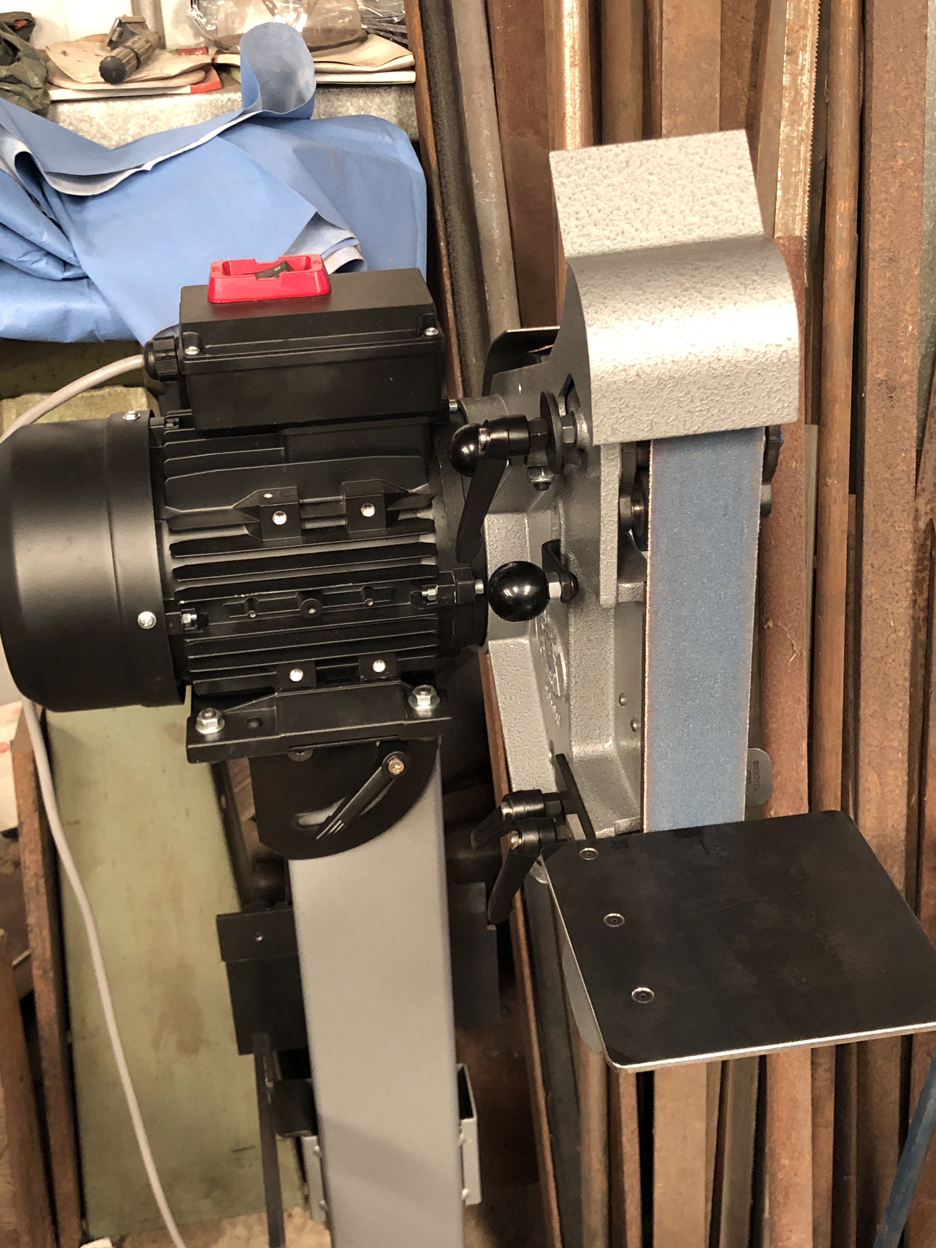
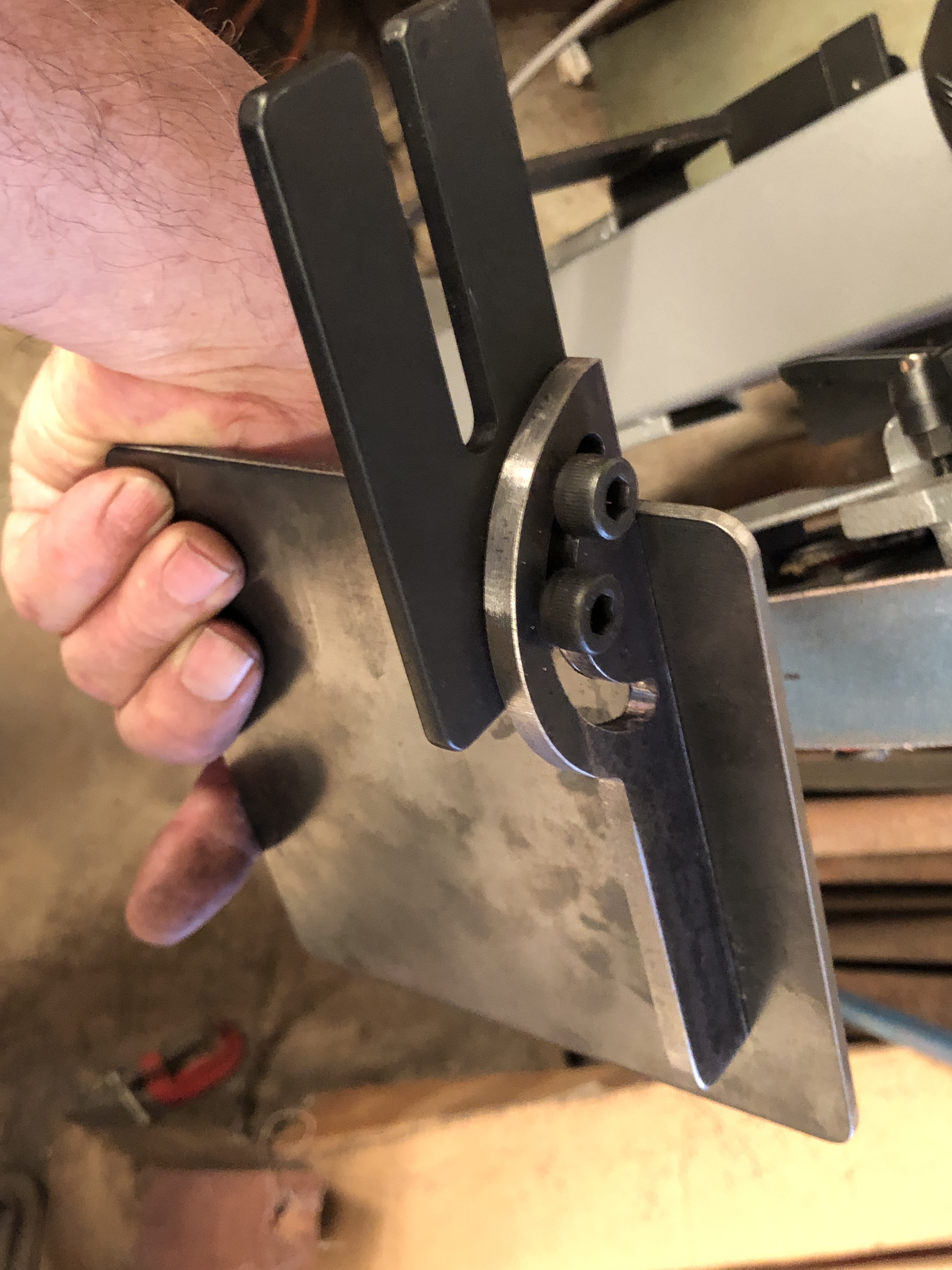
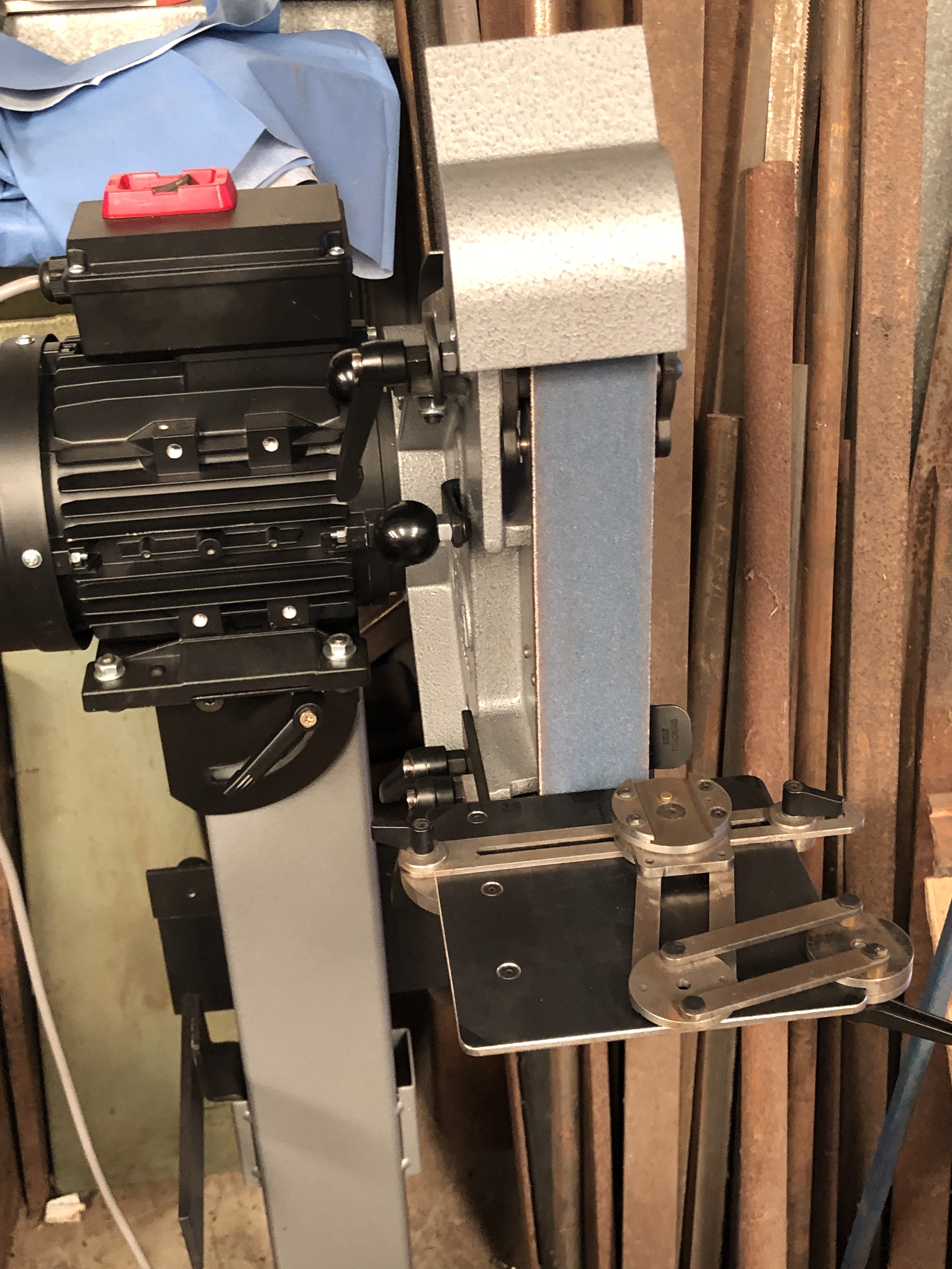
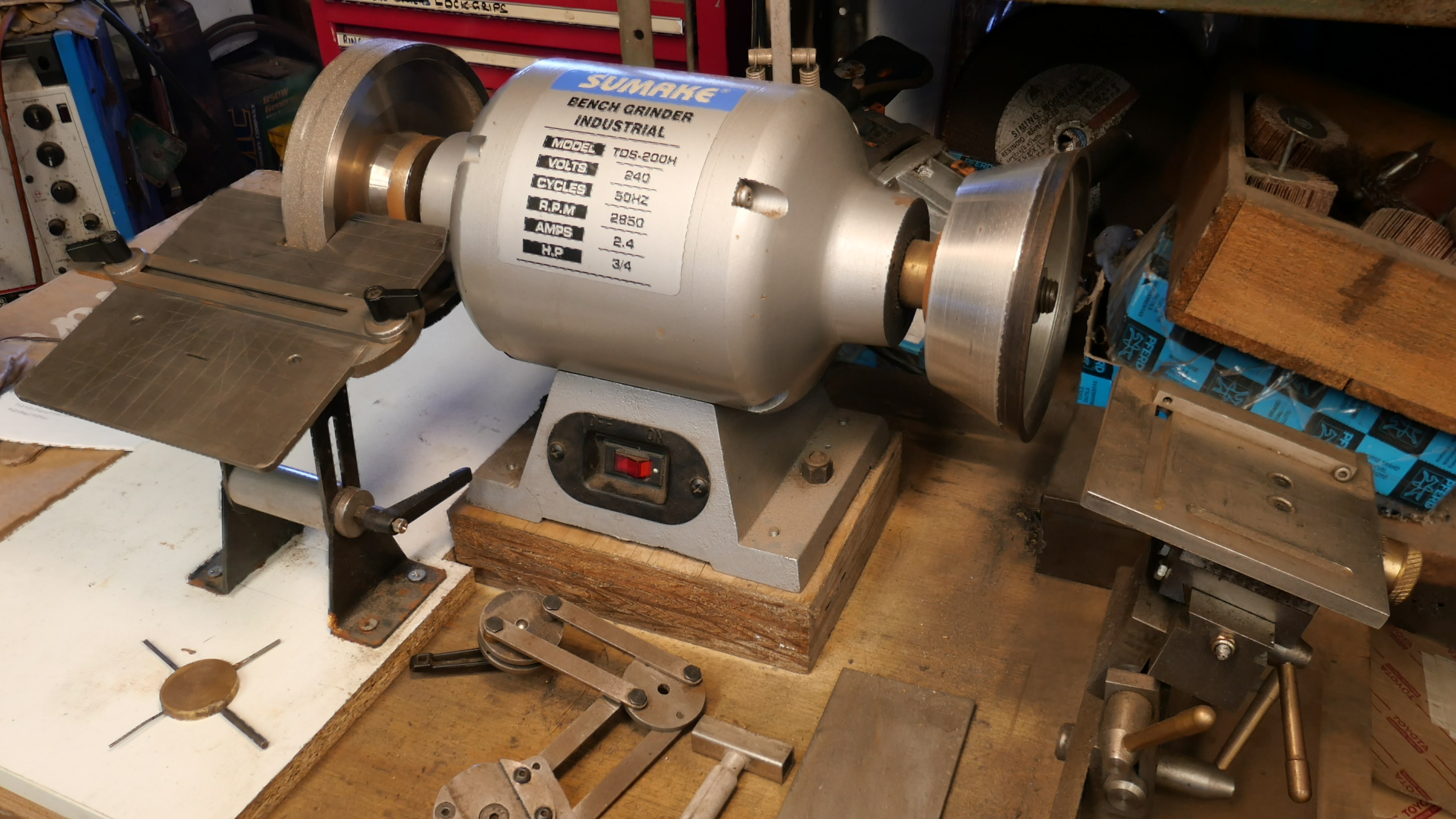
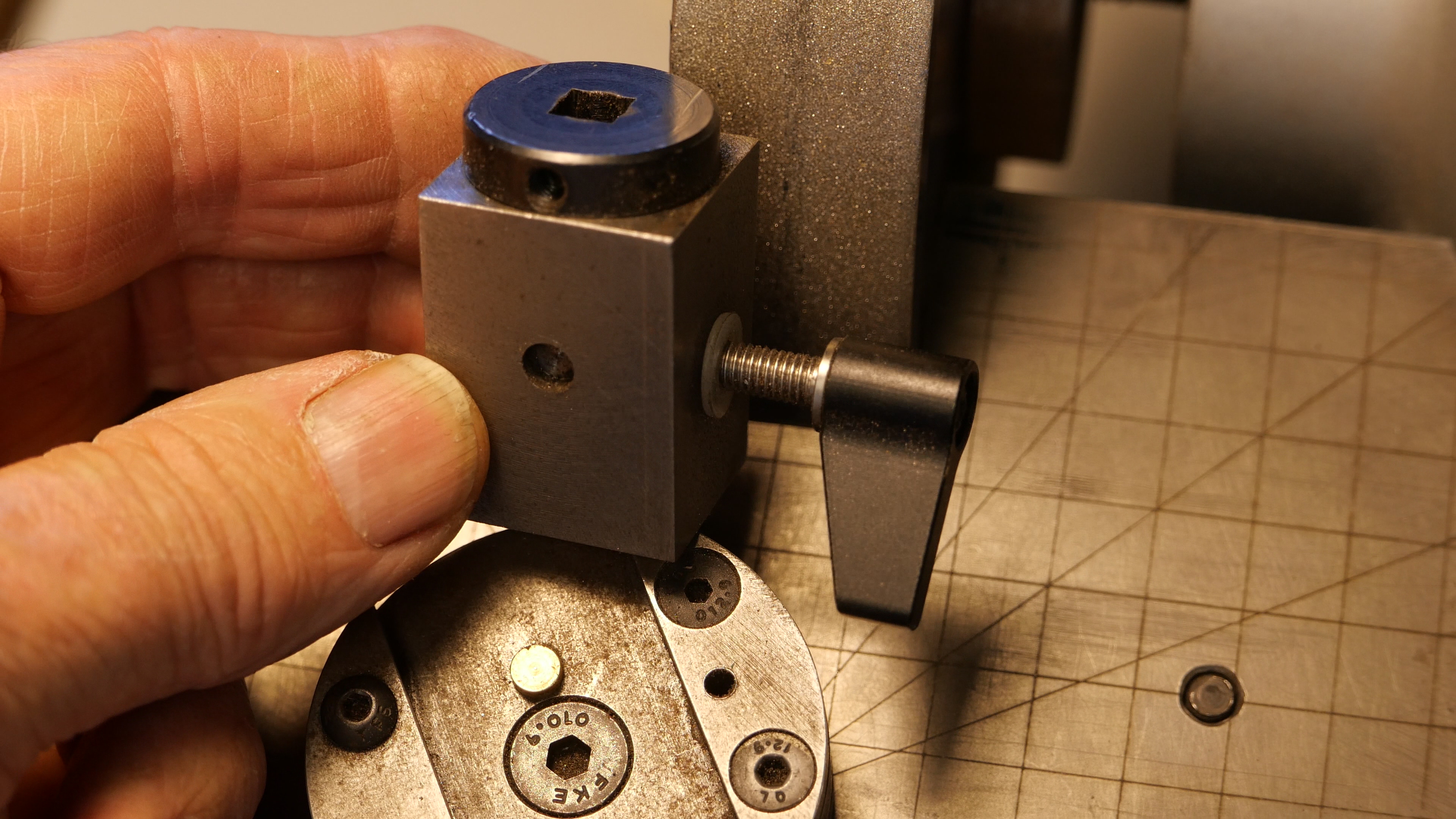
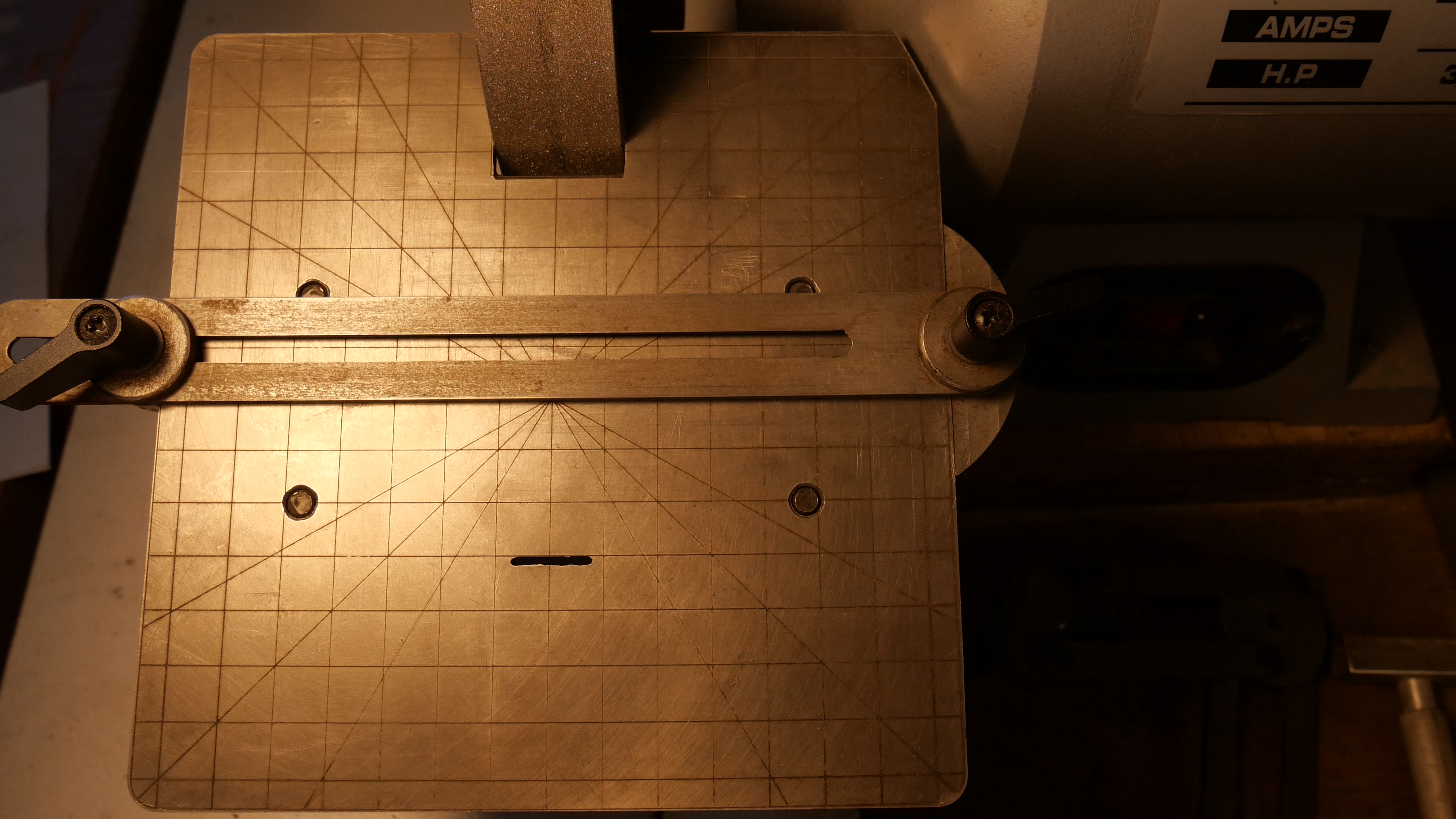
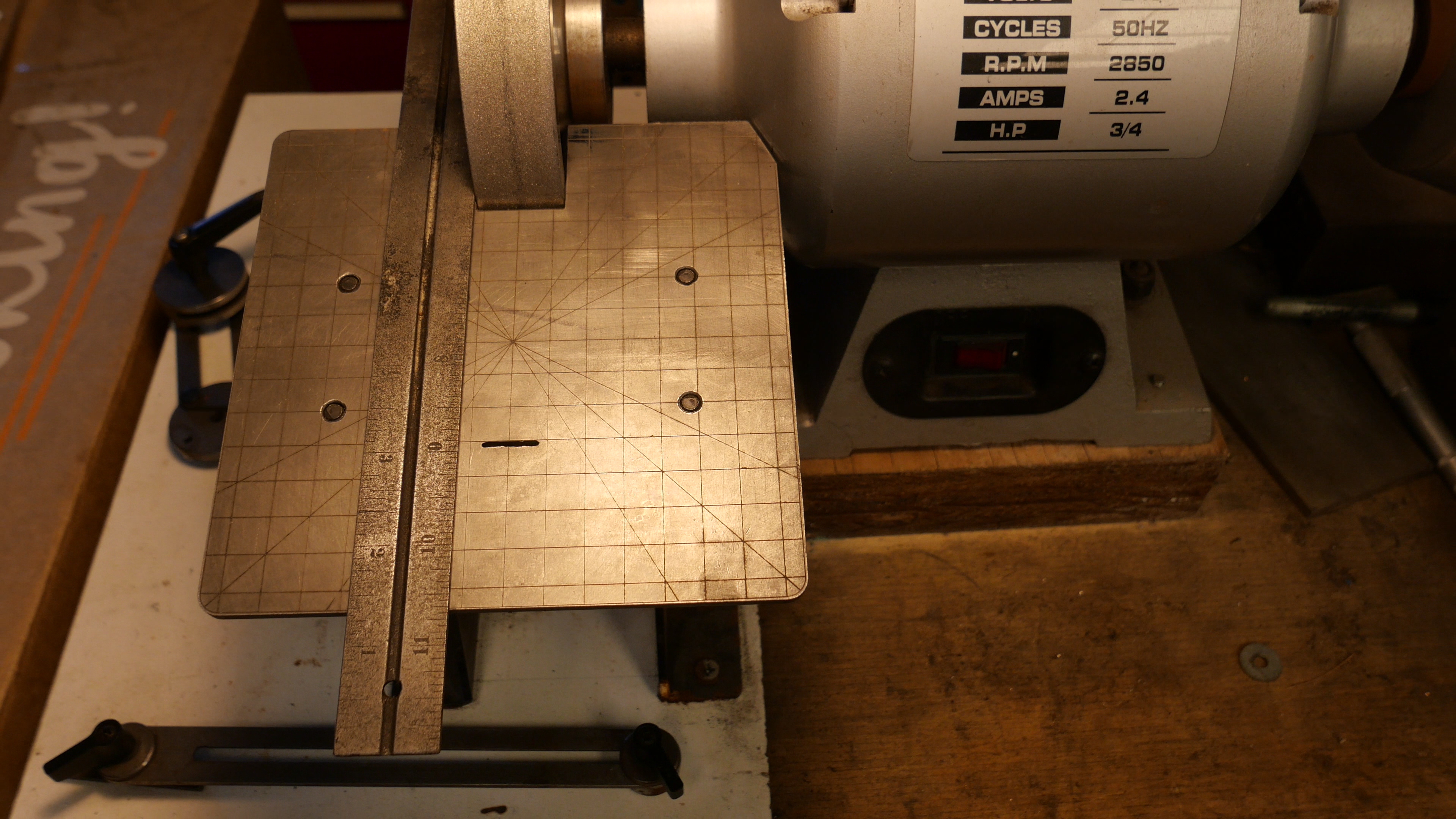
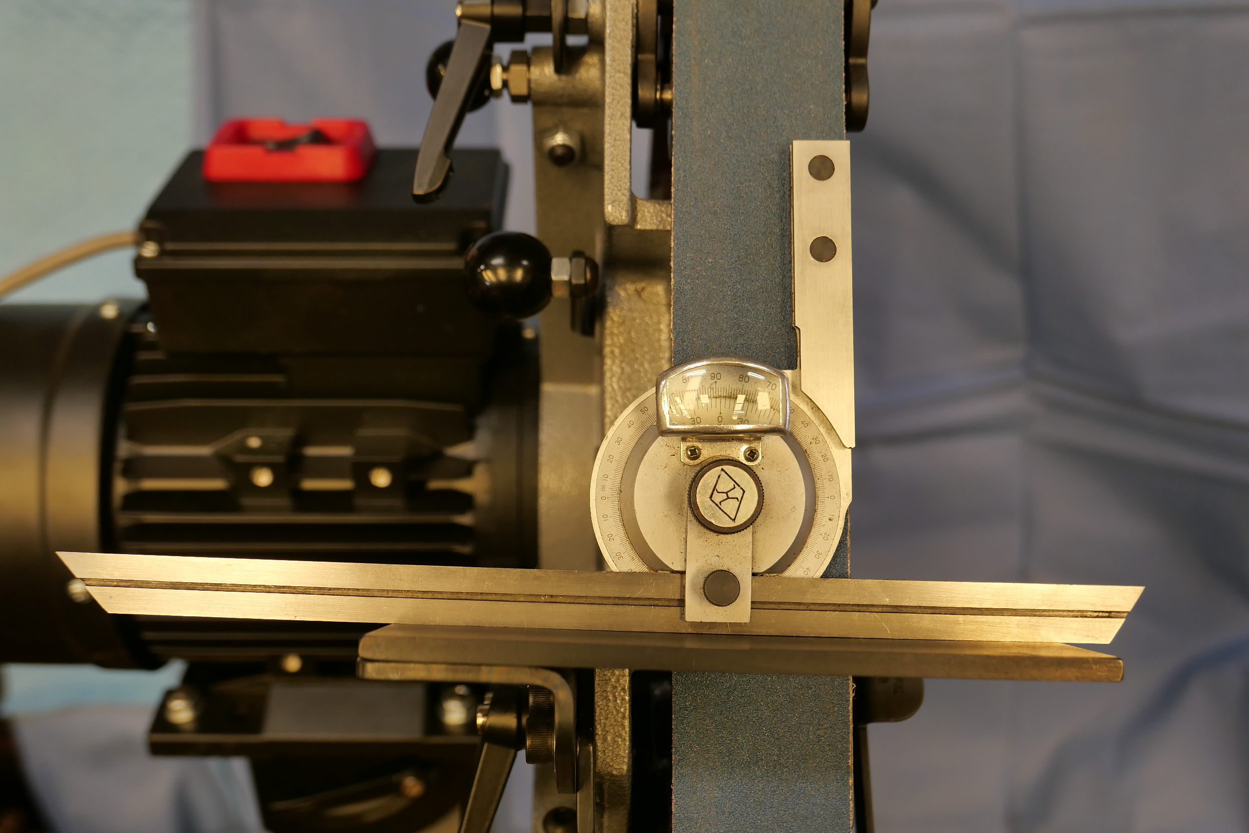
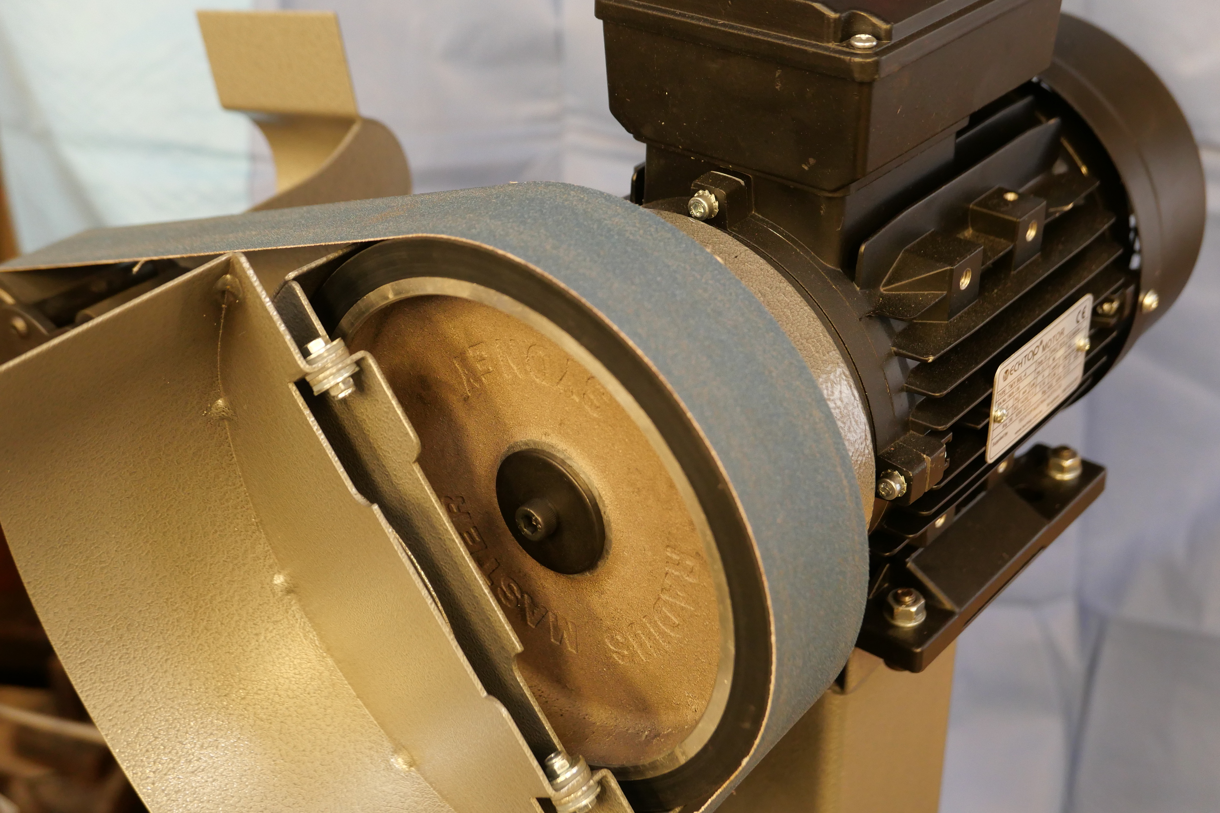
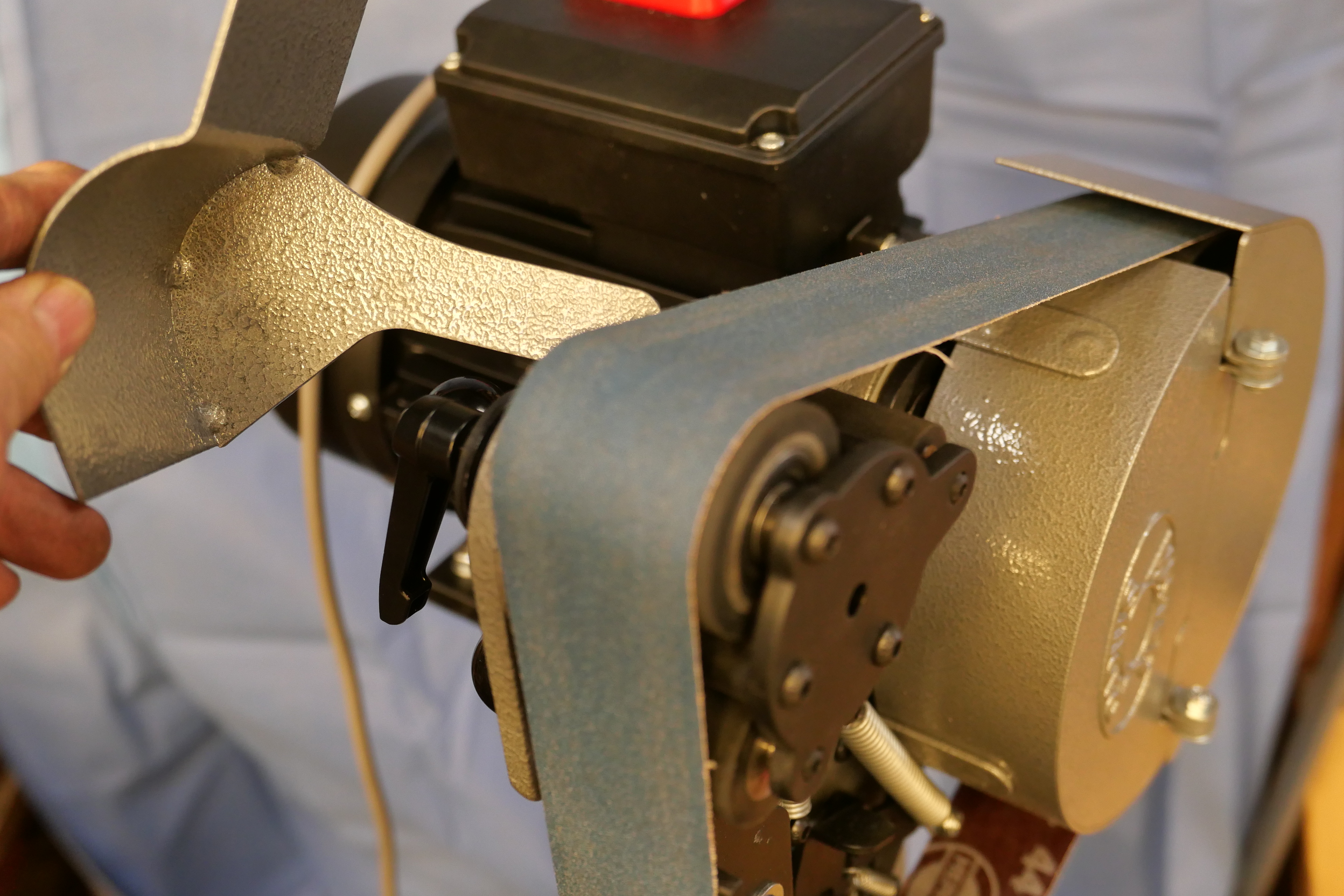
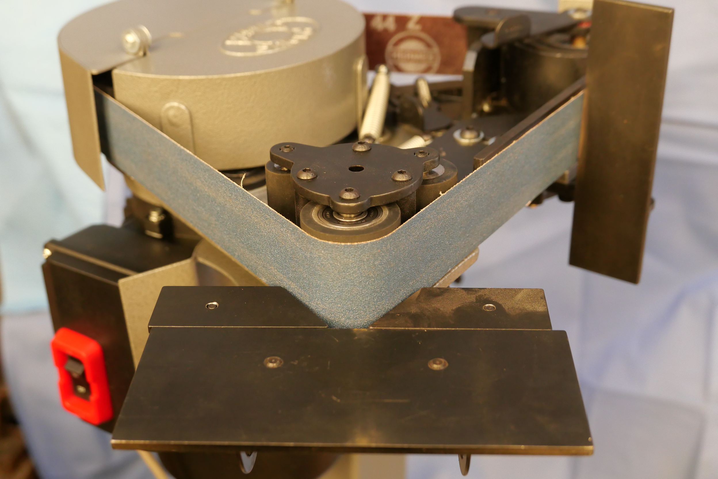
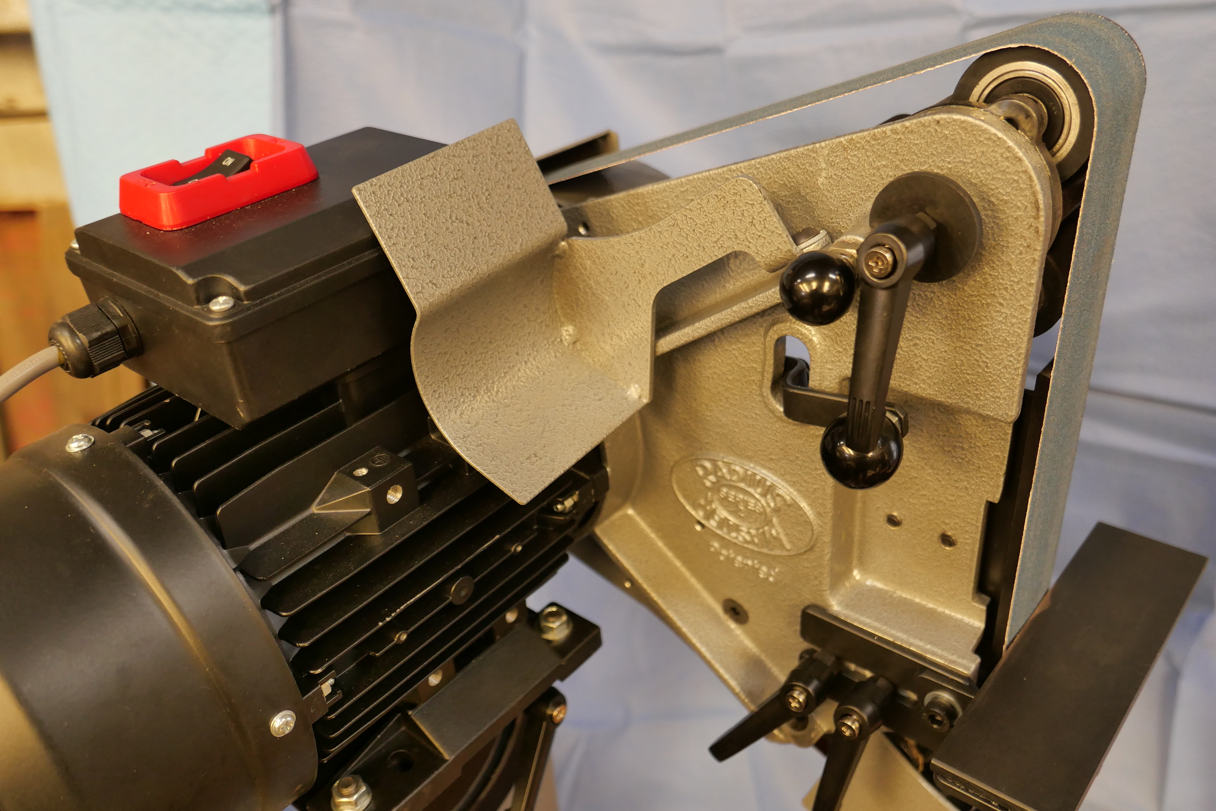
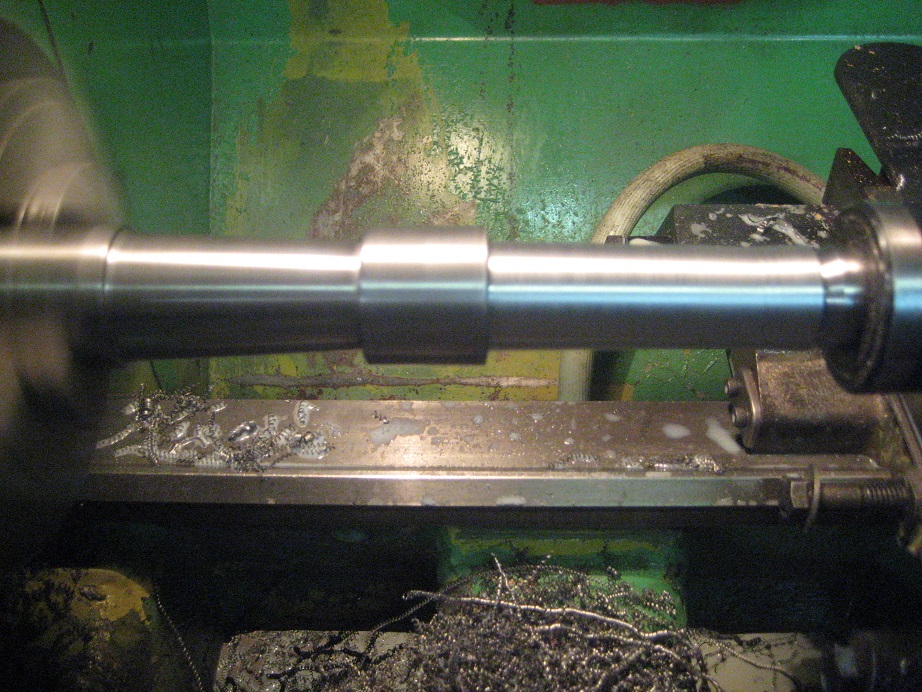
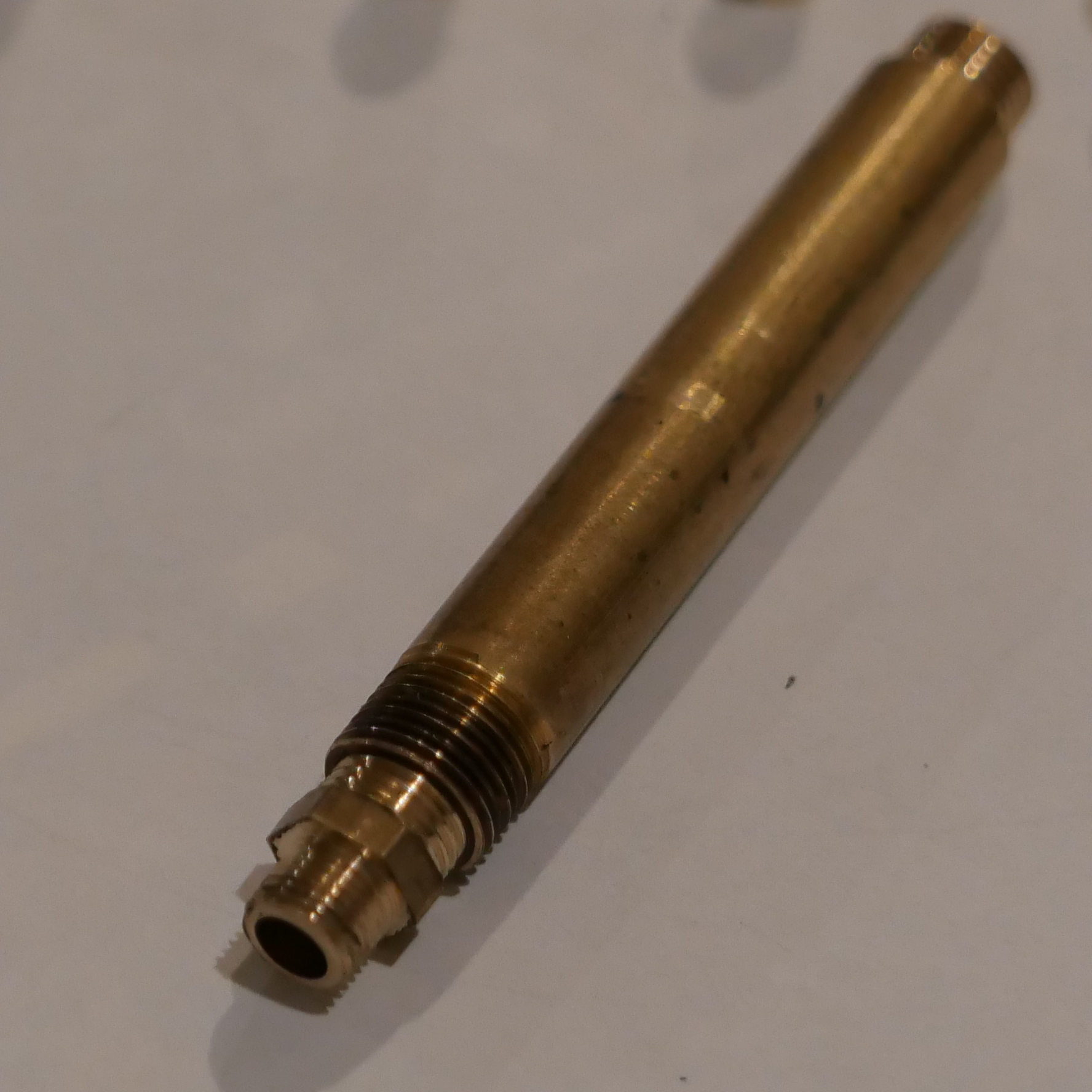
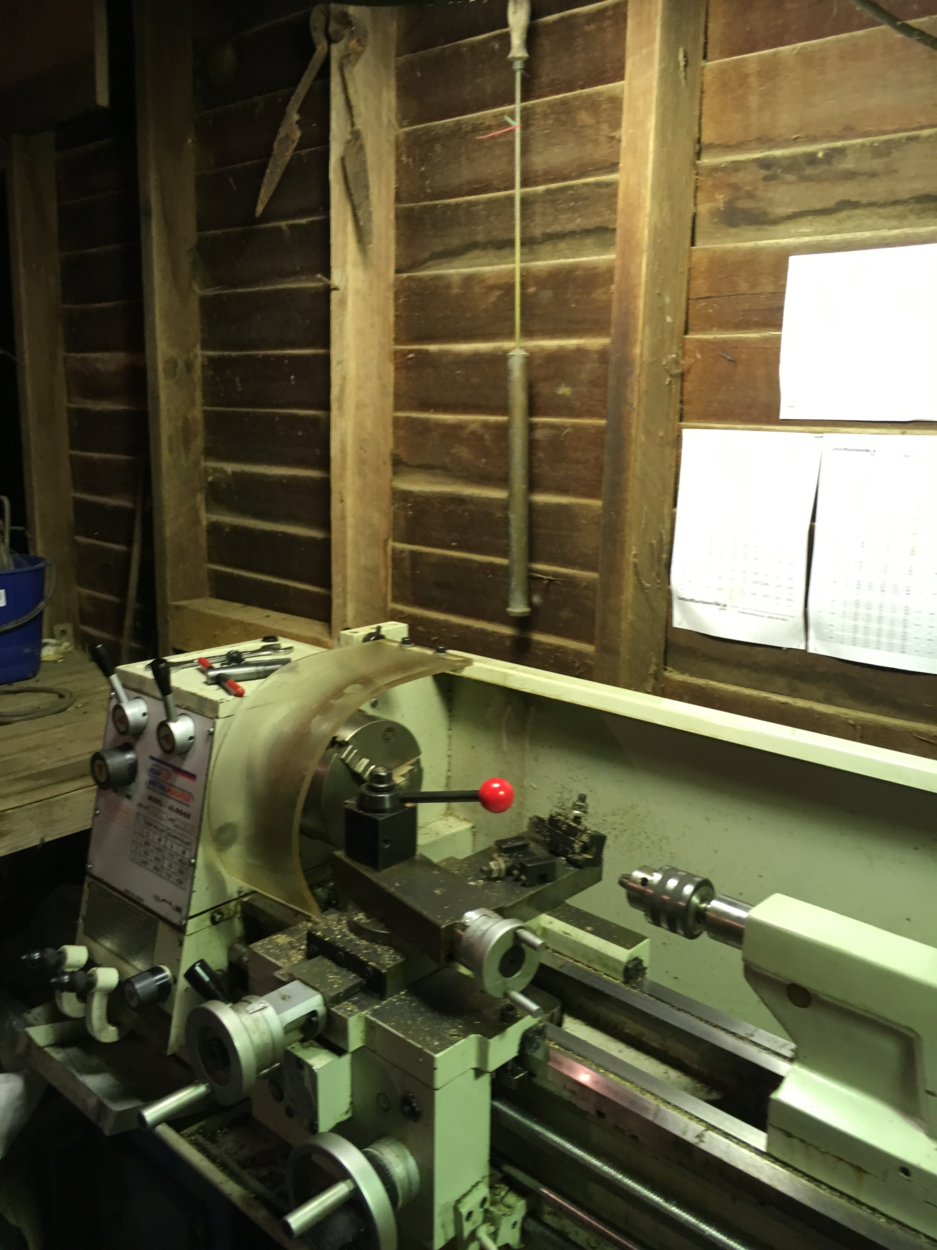
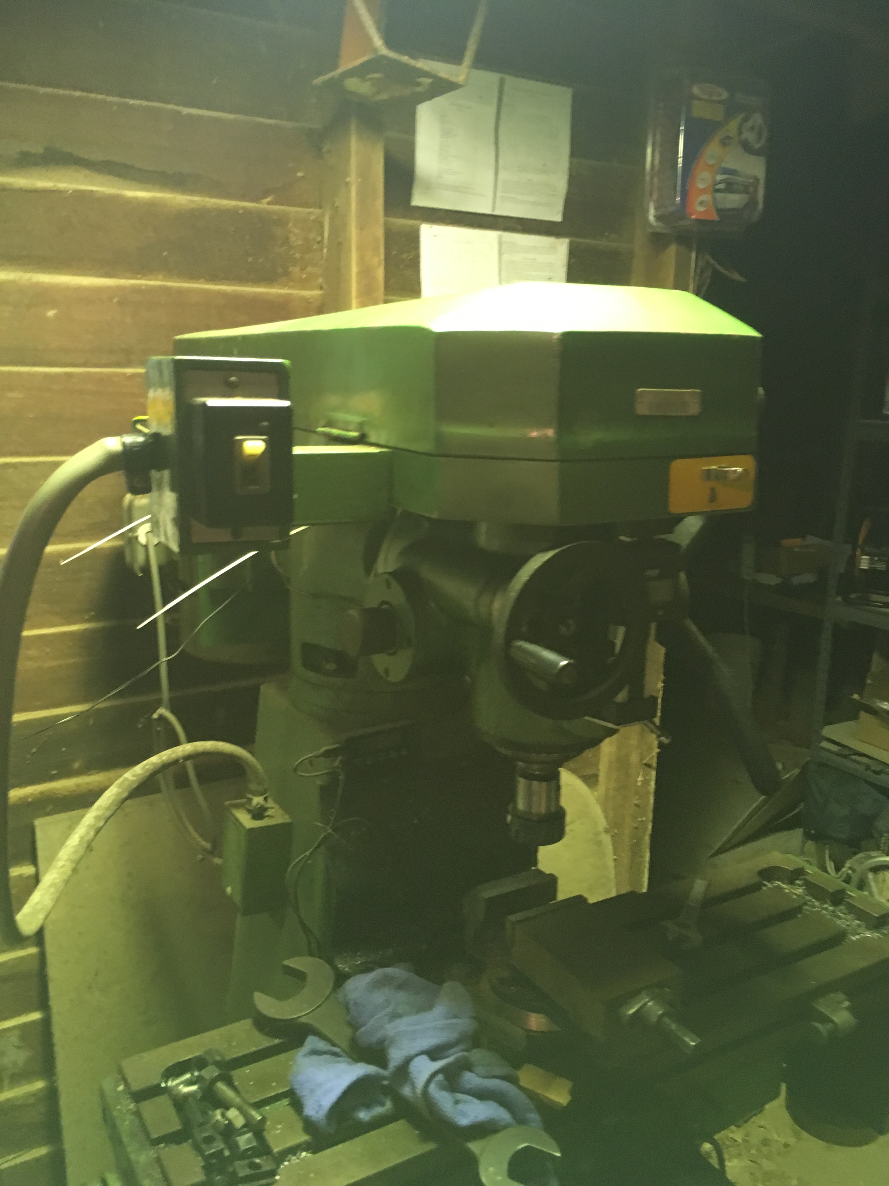
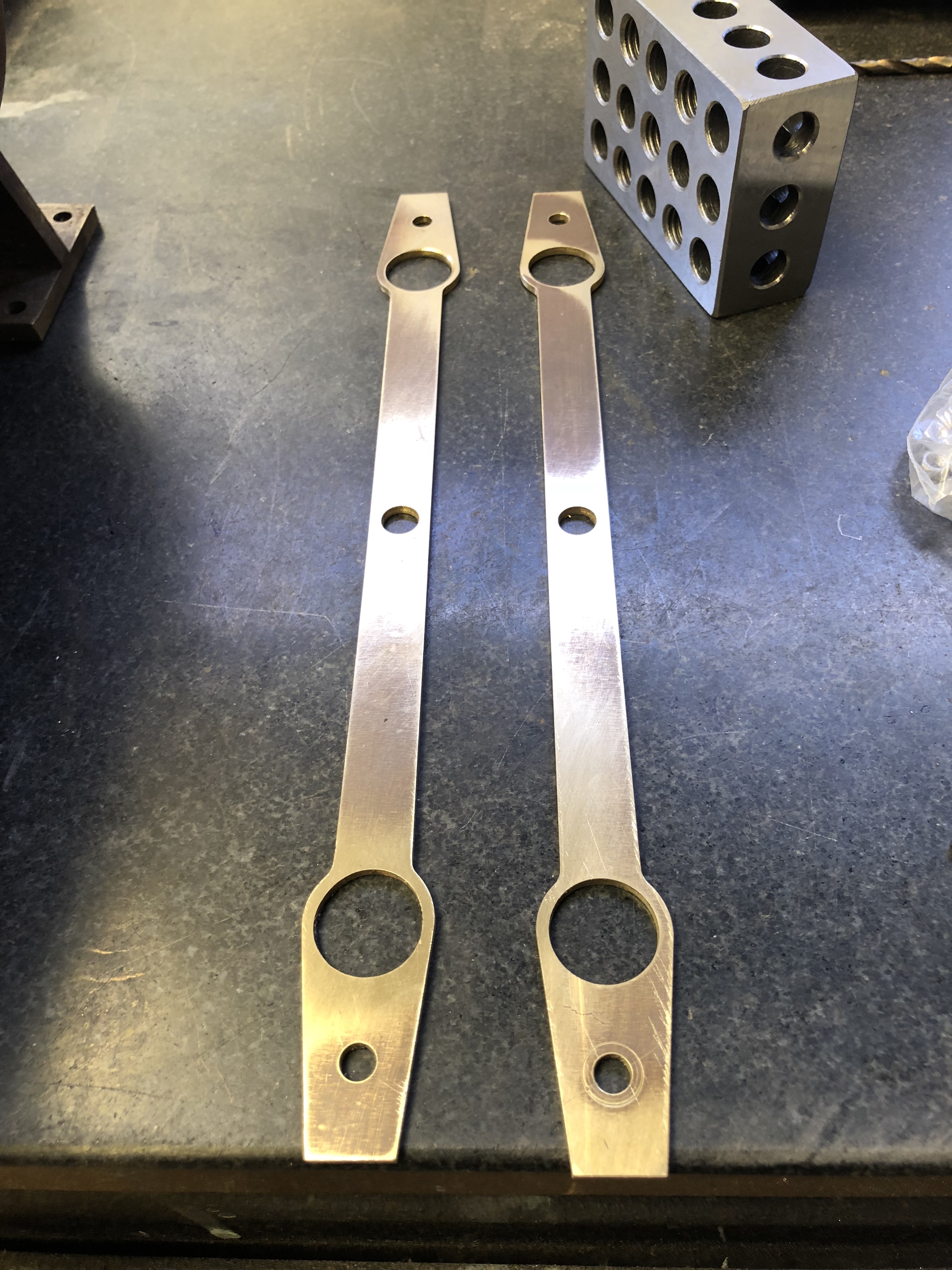
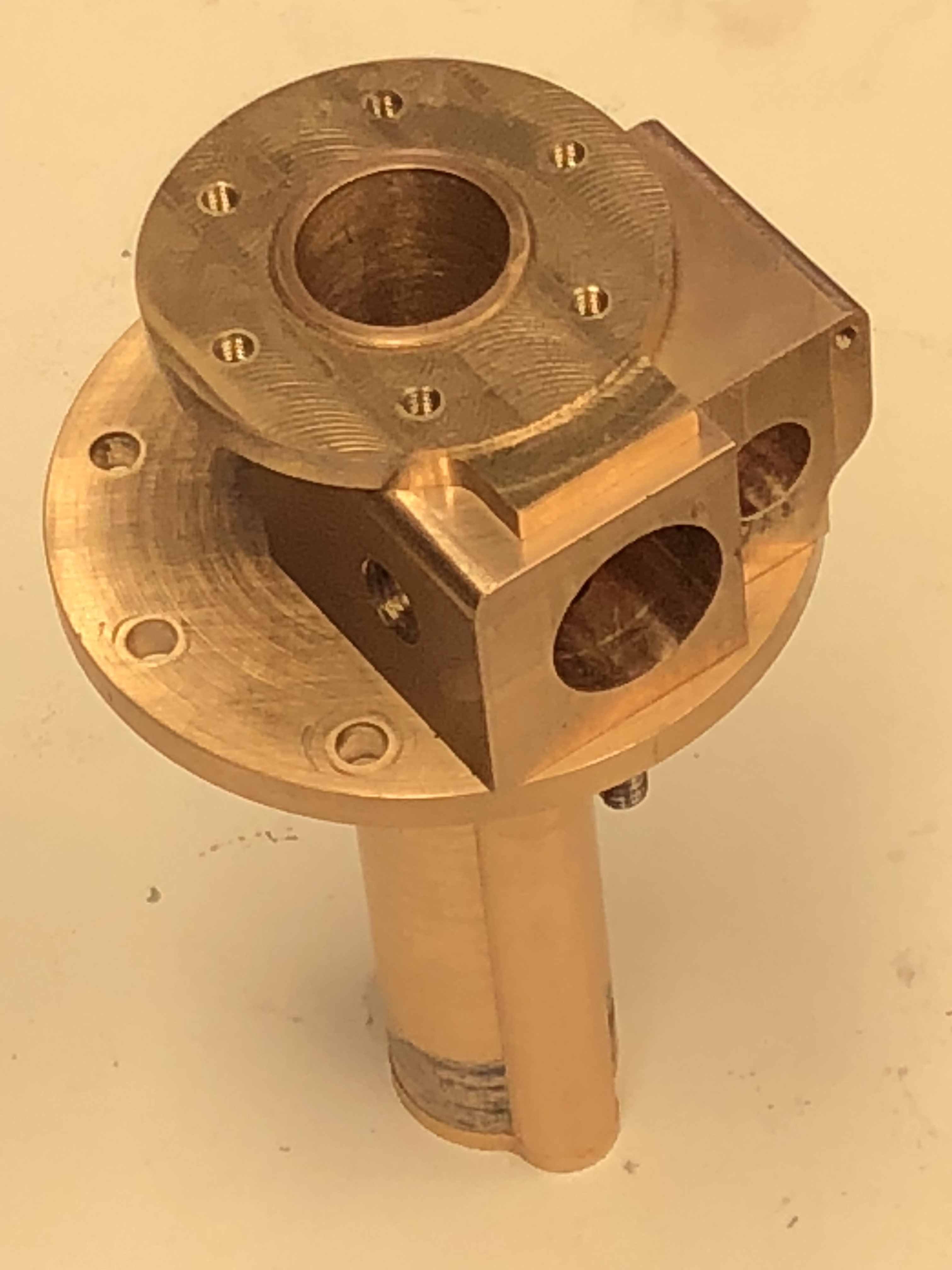
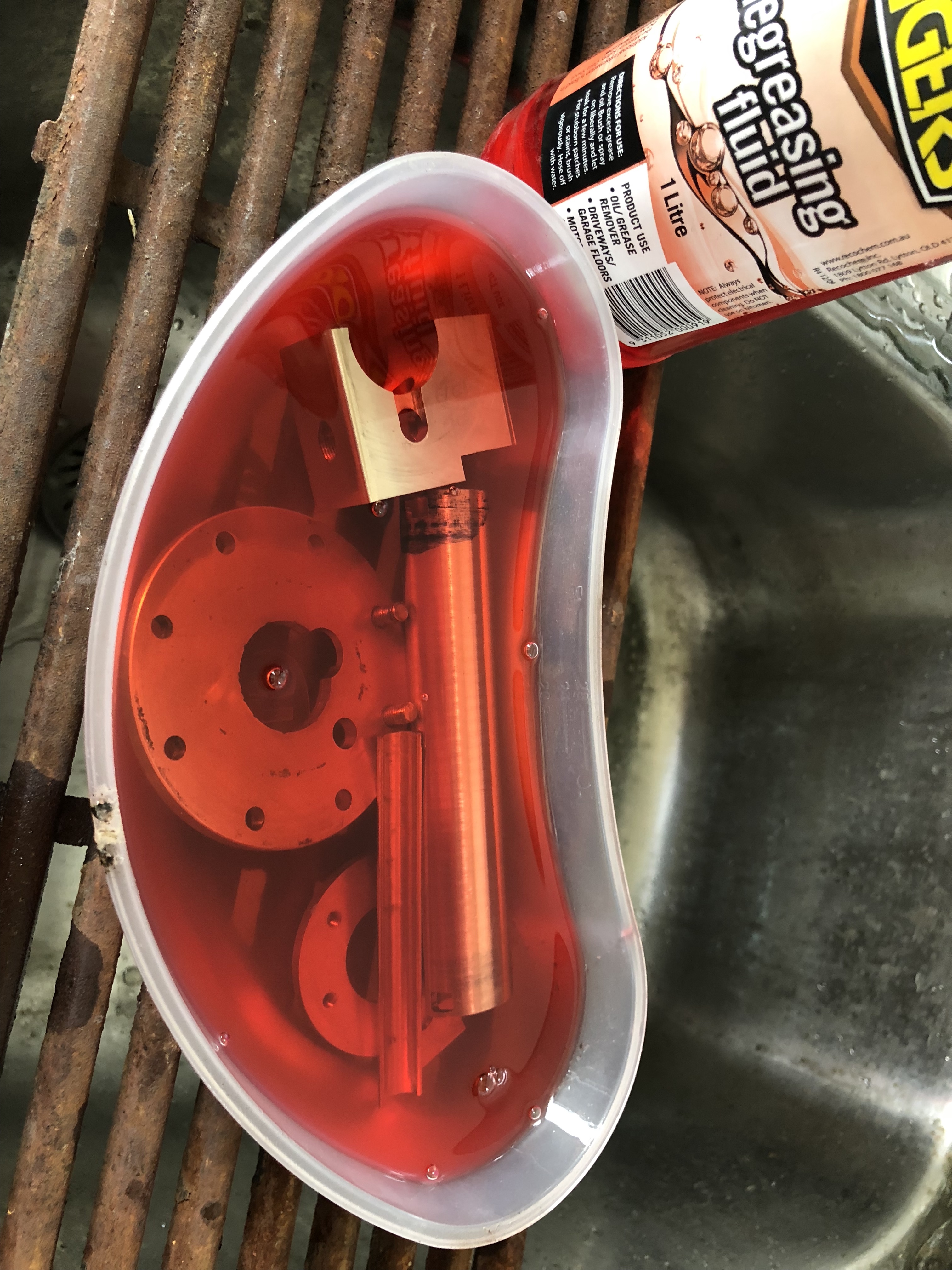
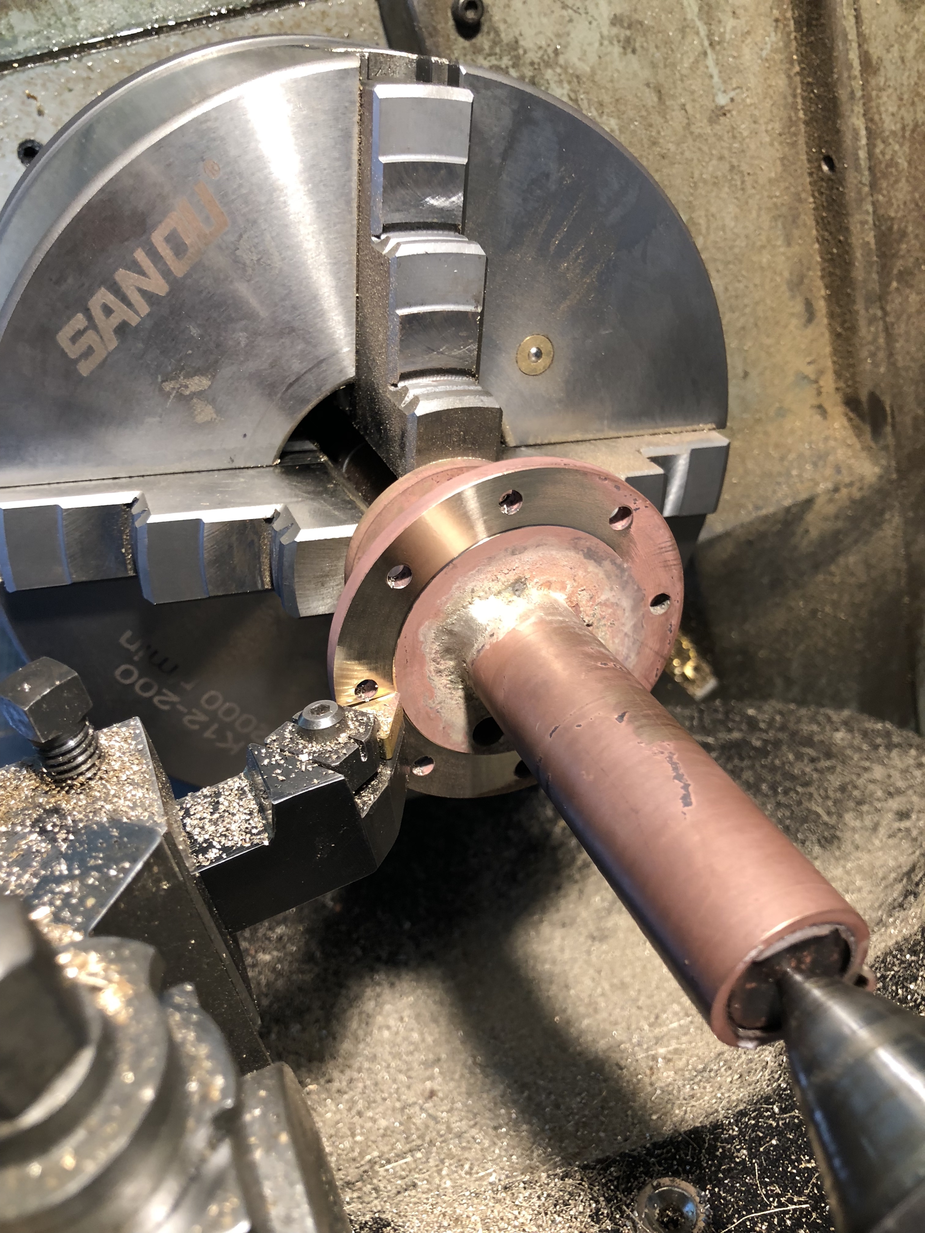
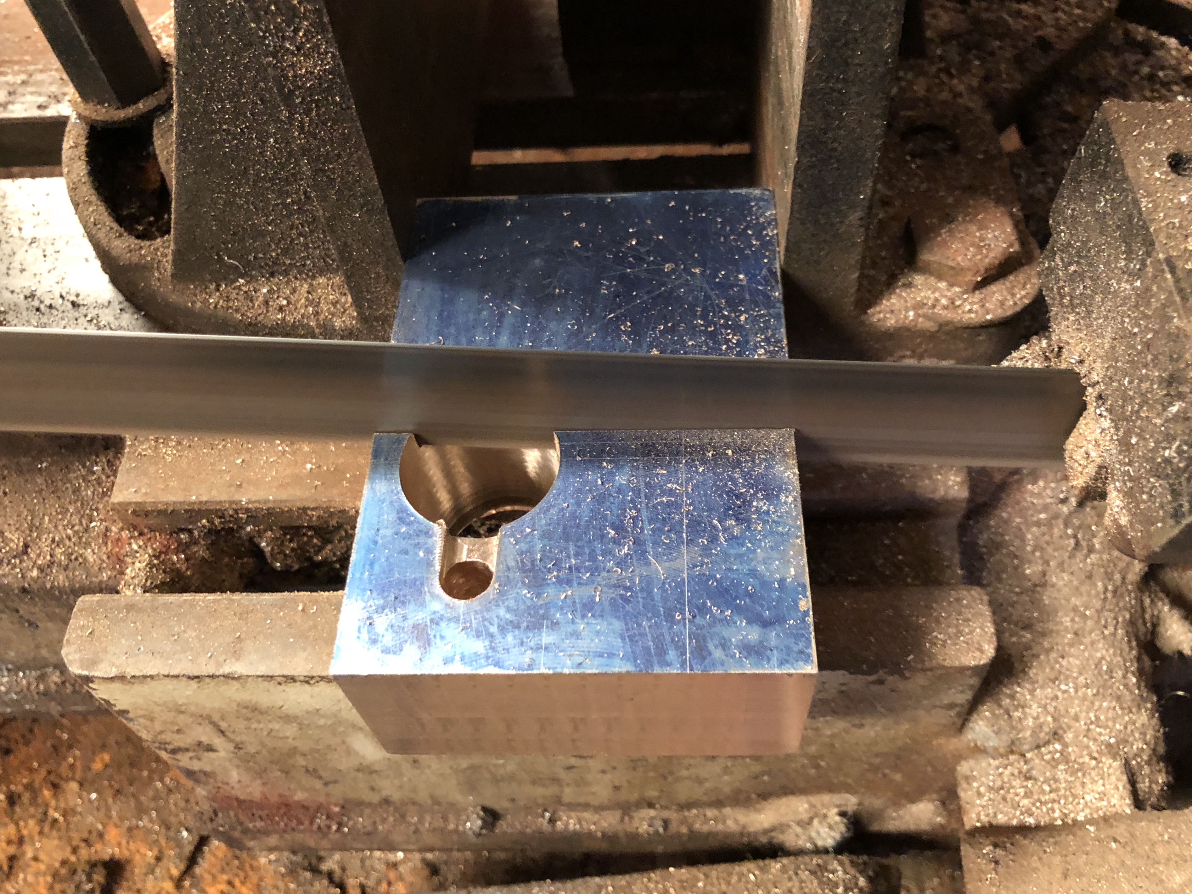
First Steam Locomotive.

In 1802 a Richard Trevithick designed engine was made by the Coalbrookdale company.  Not much is known about it, but is recorded that the steam pressure reached 145psi!  Trevithick had previously operated his road steam locomotive up the Camborne Hill, but this was the first one to run on rails.

The next one was made for the steelworks at Merthyr Tidfil, Wales.  It was a Trevithick engine which ran on rails.  The owner made a 500 guinea bet with a rival (an astronomical figure.  Somewhere I read that it would be equivalent to a million dollars these days), and in Feb 1803 the engine towed 5 wagons, loaded with 10 tons of iron ore (or coal, not sure), and 70 odd bods, a distance of 10 miles.  There was dispute about whether the bet had been won due to some technicalities, and no record of it being paid, but it was a moral victory.  The age of steam had really begun.

The biggest problem was not the locomotive, but the rails.  They were not strong enough, and frequently broke.  It took the genius of George Stephenson to solve that problem, by using forged iron in preference to cast iron.  And his son Robert to increase the efficiency of the engine and boiler in the form of “Rocket”.  But that is another story, for 30 years later.

Unfortunately the original of the Merthyr Tidfil loco has not survived, but several replicas have been made, based on original drawings.  I saw one of them at Swansea, Wales, not far from Merthyr Tidfil.  Not a steaming day.  It does run.

P1021619.JPG

Not great photos.  The lighting conditions in the National Waterfront Museum were difficult.

P1021605.JPG

The typical big, skinny Trevithick flywheel, and driver’s wagon.

P1021607.JPG

Square main shaft.  Hex nuts were not around in 1802.  

P1021629.JPG

And that is a view that you don’t often see.  The pressure gauge is definitely a modern requirement, as I discovered with my dredger engine.

P1021625.JPG

Notice the fish belly rails.  Originals were cast iron.  “Fish belly” shape to increase the strength, but alas, not strong enough.  Hex nuts again!  And those gears have modern shaped teeth.  Quite a few compromises in this replica.

And I have now arrived in Camborne, Cornwall, Trevithick’s home, and the site of his famous trial of the steam road loco.

I made a pilgrimage to Fore St (“Camborne hill”), then to his statue, to pay homage.

P1021728.JPG

Richard Trevithick.  Genius.


Lathe Woes

Removed the gear with the broken tooth from my GBC 400-1000 lathe yesterday, with some help from my brother.    Approached the disassembly a bit nervously.  Did not want to break or damage anything else.

First took some photographs, so I can put things back together eventually, in the correct places and order.

Then removed the chuck, then the back gears, then the large heavy plates at each end of the spindle.  The cap screws came out without any drama, but the end plates required breaking free of the paint, and out of the tightly fitting mounting rebates.

Then loosened the big nuts against the internal gears, the external gears, and one grub screw.

img_7853.jpg

Tabbed locknut undone, allowing the gear cluster to be slipped and driven towards the left, eventually allowing the spindle to be removed.

Gradually removed the spindle by tapping the gears along the spindle with brass drifts.  Pretty tight.  And retrieved the little bits as they fell into the oil in the headstock.

Was finally able to lift the spindle out through the chuck end of the headstock.  It is heavy.   Took two of us to lift it out without damaging the outer races of the tapered roller bearings.

Then looked at the broken gear, and retrieved the tooth from the headstock oil.

IMG_7862

The broken tooth.  Unfortunately, on closer inspection, and adjacent tooth is also cracked.  And very likely more are on the way.   This is more serious than initially thought.  It is a big heavy gear, 240mm dia, with a 65mm long collar,

Next step was to look closely at the meshing gear.

IMG_7857.JPG

With a good light, and getting close I still had trouble checking for cracks.  Only when I looked at this photo did I realise that I had forgotten to change my sunglasses.   Ah, the joys of getting old and forgetful.

Meanwhile, I remembered a tool which might help with the inspection….

IMG_7859.JPG

It is a cheap fiberoptic inspection camera.  Worked fairly well here, and I am reasonably happy that the other gear is not cracked.   But it did convince me that I should have bought a better quality fiberoptic camera.  Put it on the wish list.

So, I have a large, hardened steel gear with at least 2 cracked/broken teeth.  Options?….

  1. Buy a new gear.  I will try, but not confident.  The local importer of these particular Chinese lathes went out of business last year.
  2. Get a new gear made.  I will get a quote.
  3. Make a new gear myself.  Or, if all else fails….
  4. Machine off the teeth of the damaged gear, and the adjacent 20-30mm.   Then make a new set of teeth on a ring which will be attached to the old core of the damaged gear.
  5. Use the lathe without that gear.   This option does not appeal.
  6. Install a VSD and use electronic control of spindle speeds.  The main spindle motor is 5HP, so it is possible.

More information required.  Watch this space.

Read the rest of this entry »

Video of the gas burner which works

The first 6 minutes of the video  is getting up to 40psi.  Then a couple of minutes of the engine working.   Big file, so be patient.

Trevithick Dredger Engine Guide Bars and Crosshead


IMG_7119.jpg

As you can see from the photo, I have made the vertical guides, the curved top bar and the crosshead.


IMG_2749.jpg

The curved bar was bent in the motorised ring roller which I made years ago.  Bending 3.2mm steel was easy.  I have bent steel bar up to 10mm thick in this machine.

IMG_7117.jpg


IMG_7118.jpg

Parts of the guide bar.  2mm thick.  I confess that these were CNC’d.


IMG_7120 2.jpg

A few more parts required for the crosshead, but a test fit was quite good.  It is just pushed together at this stage.


Trevithick Dredger Engine- Valves

No workshop posts for a while because I have been making parts for the internals of the engine, and when installed they are not very photogenic.

Since the last post I have made the piston, piston rod and installed soft packing to seal the piston, made the valves and valve handles..


IMG_7103.jpg

Stainless steel piston rod, bronze 20mm dia piston, and soft packing inserted into the machined groove.

Also made the throttle valve and steam direction valve.


IMG_7107.jpg

This was the third attempt at making a steam valve.  I went slightly undersized with the first, totally buggered the O ring groove on the second, but the third one looks OK.


IMG_7108.jpg

Good one (I hope) on the left, and destroyed one on the right.  The lathe tool bit into the bronze.


IMG_7109.jpg

From left to right.  The bush, the undersize, the buggered, and the OK I hope.  and the plans.

And after all of that, and also making the throttle valve, I discovered a mistake in the plans.  A 1mm discrepancy, which I suspect was an arithmetic mistake on the part of the plan maker.  I decided to modify the valves, bush and valve block rather than remake the valves.


IMG_7110.jpg

I machined 1mm off the faces shown in the photo, then spent some time prettying it up.  Then took 1mm off the valve lengths, and the valve bush.


IMG_7111.jpg

This is what it looks like now.  All fixed.  Waiting for Viton O rings to arrive.  Looks OK IMO.


Soldering the Trevithick Dedger Engine

That is soldering.  Not soddering.


IMG_7082.jpg

These are the engine cylinder, valve chest, steam pipe (on the side of the cylinder), and flanges, pushed together.  I took this photo, because never again will these bronze parts look so pristine. 

IMG_7083.jpg


IMG_7084.jpg

Firstly, a thorough soak in degreaser, then rinsed in water.


IMG_7085.jpg

Then the steam transfer tube was wired into position.   All joins were fluxed, then silver soldered.   Then a soak in sulphuric acid and a water rinse.  


IMG_7089.jpg

The 20mm bore still accepted a 20mm diameter silver steel rod (i.e. no significant distortion from the heat), so the rod was super glued in place, and used to turn the flanges flat and perpendicular to the bore.


IMG_7090.jpg

The assembly was heated to release the super glue.


Trevithick Dredger. A start on the Engine.

Some photos of progress on the Trevithick Dredger engine.  I am still making components for the engine, which is a single cylinder, double acting steam engine.  The valves and throttle are cylindrical, which is the method used by Trevithick over 200 years ago.


IMG_7074.jpg

From the left…  the cylinder, with rectangular steam ports and bottom cap; flanges; steam tube.  The steam tube was bronze rod which was OD turned, then drilled, then split longitudinally, then bevelled so that it fits snugly to the outside of the cylinder.  Tricky machining, done with a steel plug to avoid squashing the part in the milling vise.    Some of the 5mm holes in the large flange should have been threaded.  Error in the plans.  Now considering whether to remake the flange or thread the holes 6mm and make some stainless steel stepped studs.  Probably the studs…


IMG_7073.jpg

Components pressed together.  Later they will be silver soldered.


IMG_7076.jpg

The valve chest was made from a chunk of bronze, which was first squared up…


IMG_7077.jpg

Then marked out..


IMG_7078

After preliminary drilling and reaming, the block was sawn to produce the truncated cylindrical hole.  (any better suggestions to describe the shape?)


IMG_7079

The steam chest will contain the cylindrical valves for throttle and steam opening-closing and direction.  A complex item.  Quite a few hours of nutting out and machining.  Not quite finished.


Model Engines on Steam

It is Geelong Show time again.  It is actually titled the Royal Geelong Show, but having had more than a gutful of royal non-entities visitors being adored by unthinking cringers, flocking around Harry and Meaghan Kardashian, Windsor, and being a committed republican, I refuse to bother with the “Royal” handle.  (they are probably very nice people, I just cannot stomach the hoo-ha).

More importantly, it gives us steam junkies a chance to run our small engines on real hot steam.

For a treat, I am sharing four short clips taken today.

The first is a small beam engine, made by Swen Pettig.

Error
This video doesn’t exist

The next two engines you have probably seen before.  My beam engine, and the triple expansion engine.

The small engine to the right is a Stirling engine which is running on the heat from the exhausted steam from the beam engine.

The triple is leaking a bit more than it should, although it is running amazingly smoothly on 25-30 psi.  The valve glands need repacking.

And finally, a model IC engine, the really odd Atkinson.  A 100+ year old design.  2 stroke. Made by Rudi vanderElst


Hydrostatic Boiler Testing

The boiler on the model Trevithick Dredger Engine was ready, I thought, for the next boiler inspection.

So far the boiler inspector has approved:

  1. The plans
  2. The boiler materials
  3. The machined materials
  4. The results of the first bronze brazing session
  5. The results of the first silver soldering session

Next was the hydrostatic test of the assembled boiler components.  This is a test which involves pumping water into the boiler, and holding it there for 20-30 minutes, at double the maximum operating pressure.

I intend to operate the boiler at a maximum of 50psi, but the minimum in the AMBSC code is 60 psi, so the test will be done at 120psi.

So I assembled the boiler, with a gasket under the big flat flanged end, and tested it in my workshop.  It pumped up OK to 120-140psi, but there were several leaks.  Most of the leaks were fixed fairly easily with teflon tape, but there was a persistent ooze of water from the big flat end gasket.  It was not holding pressure.

Next step, a thicker gasket.  Some improvement, but not enough.  I was still noting a drop of water every 3-4 seconds.

Next step, gasket goo on the gasket.  Maybe some further improvement, but still not enough.

OK, what next?  Maybe the big flange, or the big flat end plate was not  perfectly flat?  So an hour or so, rubbing the flange on 600 grit wet and dry on a flat plate.  There did appear to be some distortion.  The plate had been carefully lathe turned, but maybe the heat from the brazing caused some distortion.   A further reassembly then a test still showed more oozing than I was happy about.

Finally the penny dropped!

The flange was held in place by 24 stainless steel threaded rods with square nuts holding the flat plate in place.  Some of the holes in the flat plate had evidence of the threaded rod in the form of threading marks made by the threaded rod.  These were acting like threaded holes rather than relief holes.   So I drilled them all by a further 0.5mm.   Problem solved!

Pressure held to 140-160psi, with very slow pressure drop.  The drop was caused by slight ooze from the pressure pump taped joins.  See the videos.  The occasional drip which appears in the video is coming from the leak in the pump delivery hose.

So now back to the boiler inspector….


Dredger Engine Bling

Getting ready for an exhibition tomorrow.  The organisers want “works in progress” so I am taking the dredger engine.  In its present state it is more a dredger boiler than an engine, but I doubt that anyone will mind.

IMG_7934.JPG
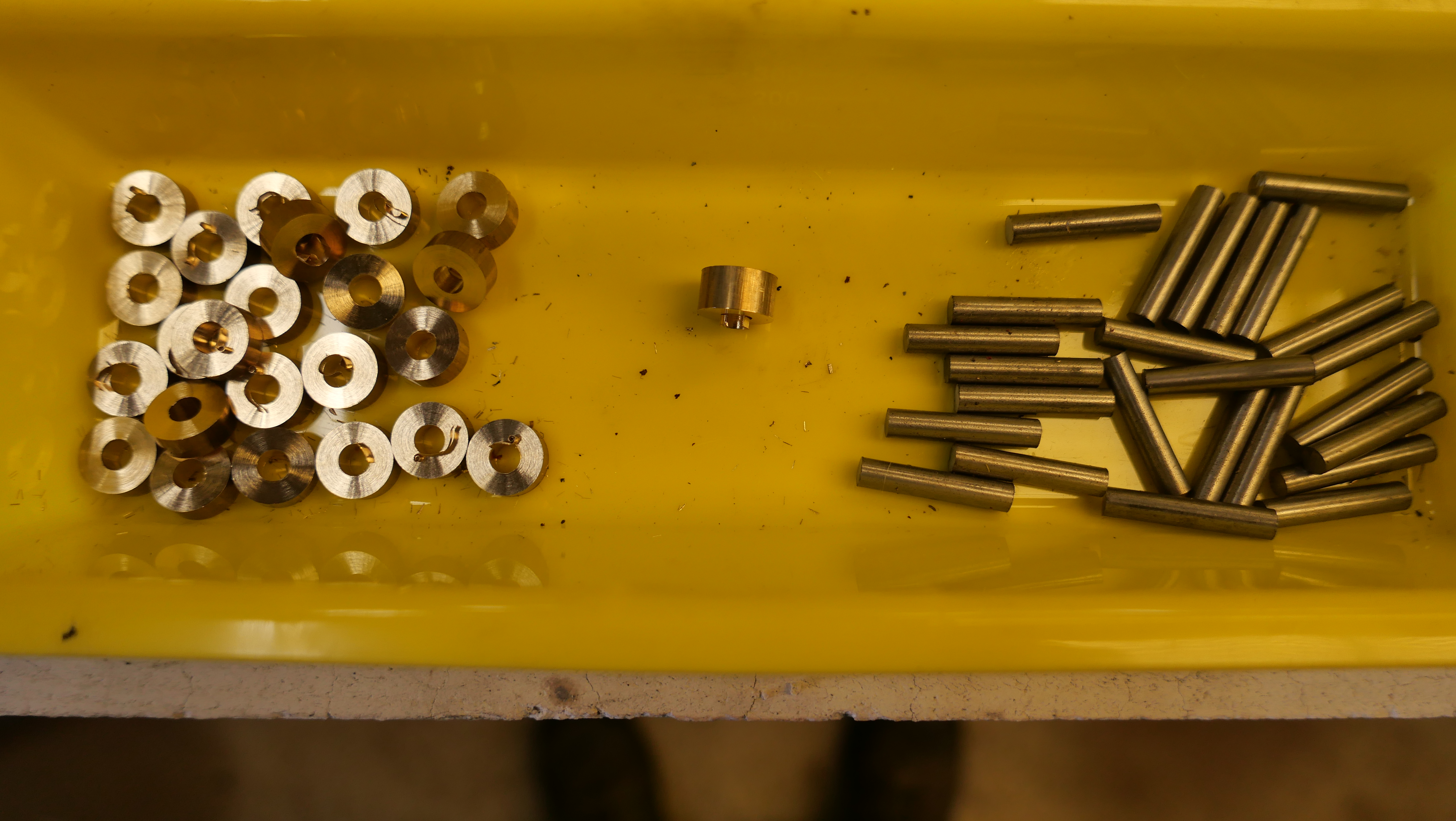
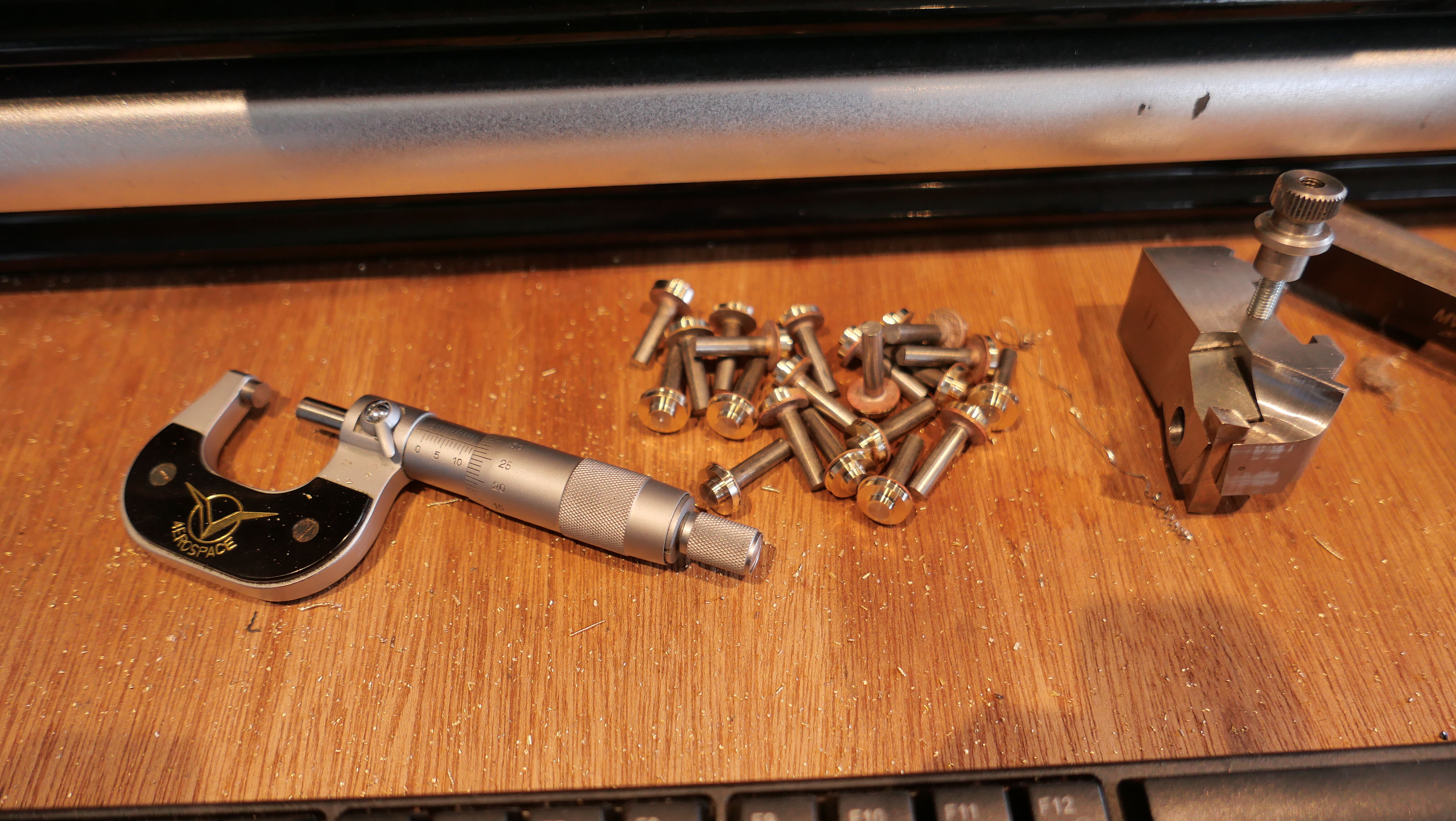
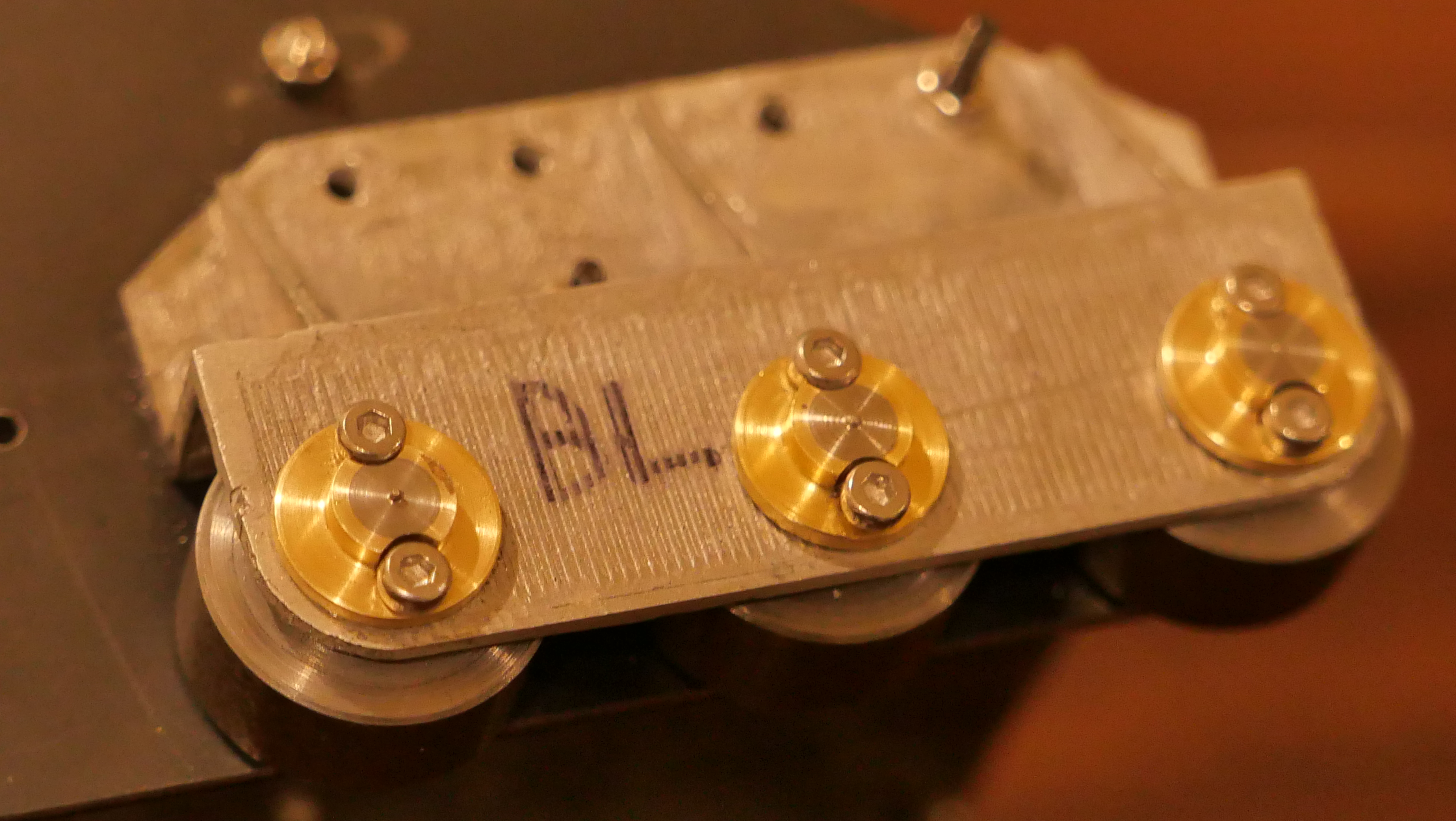
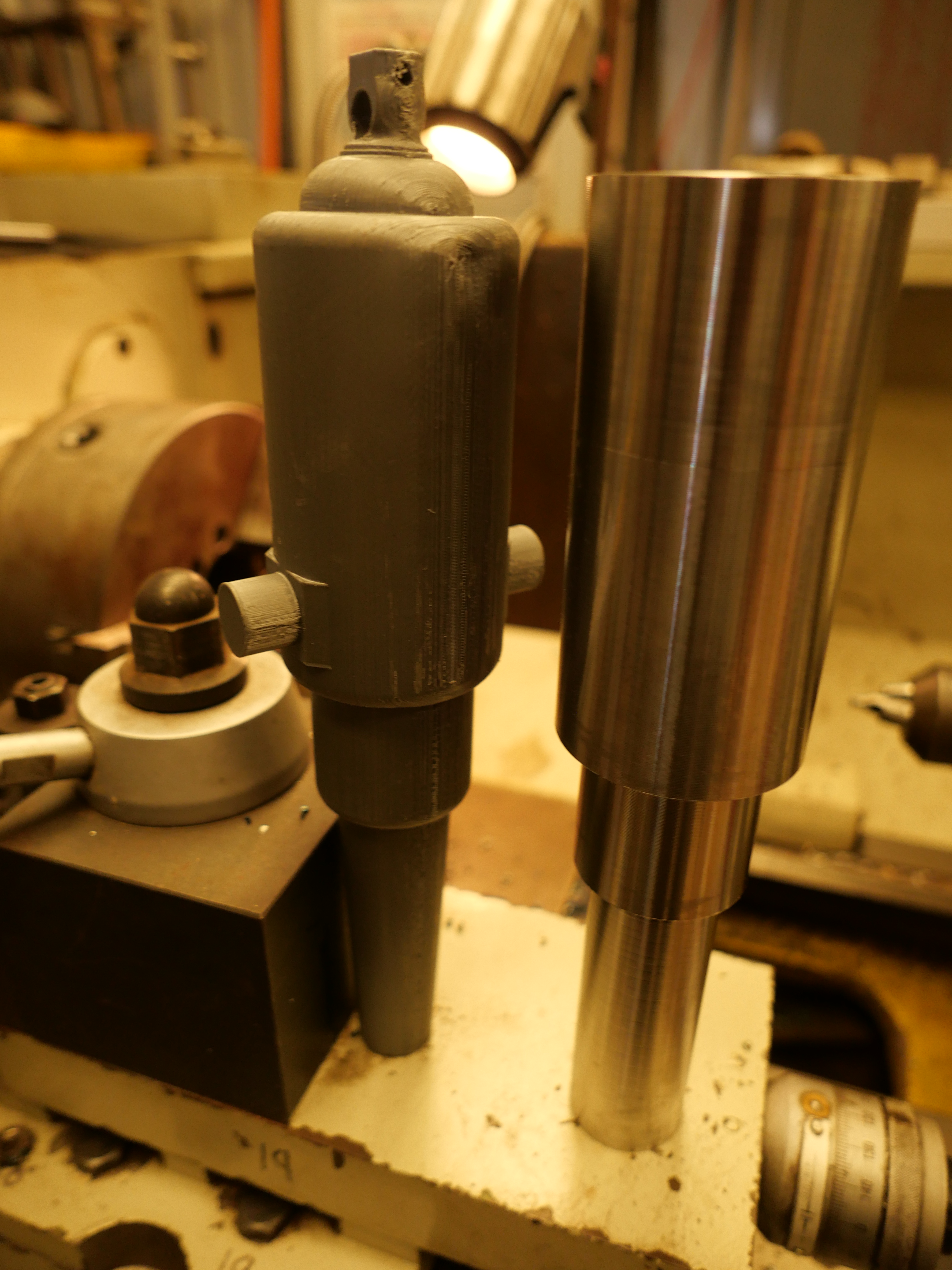
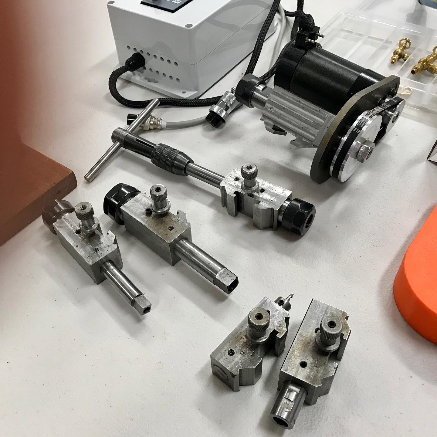
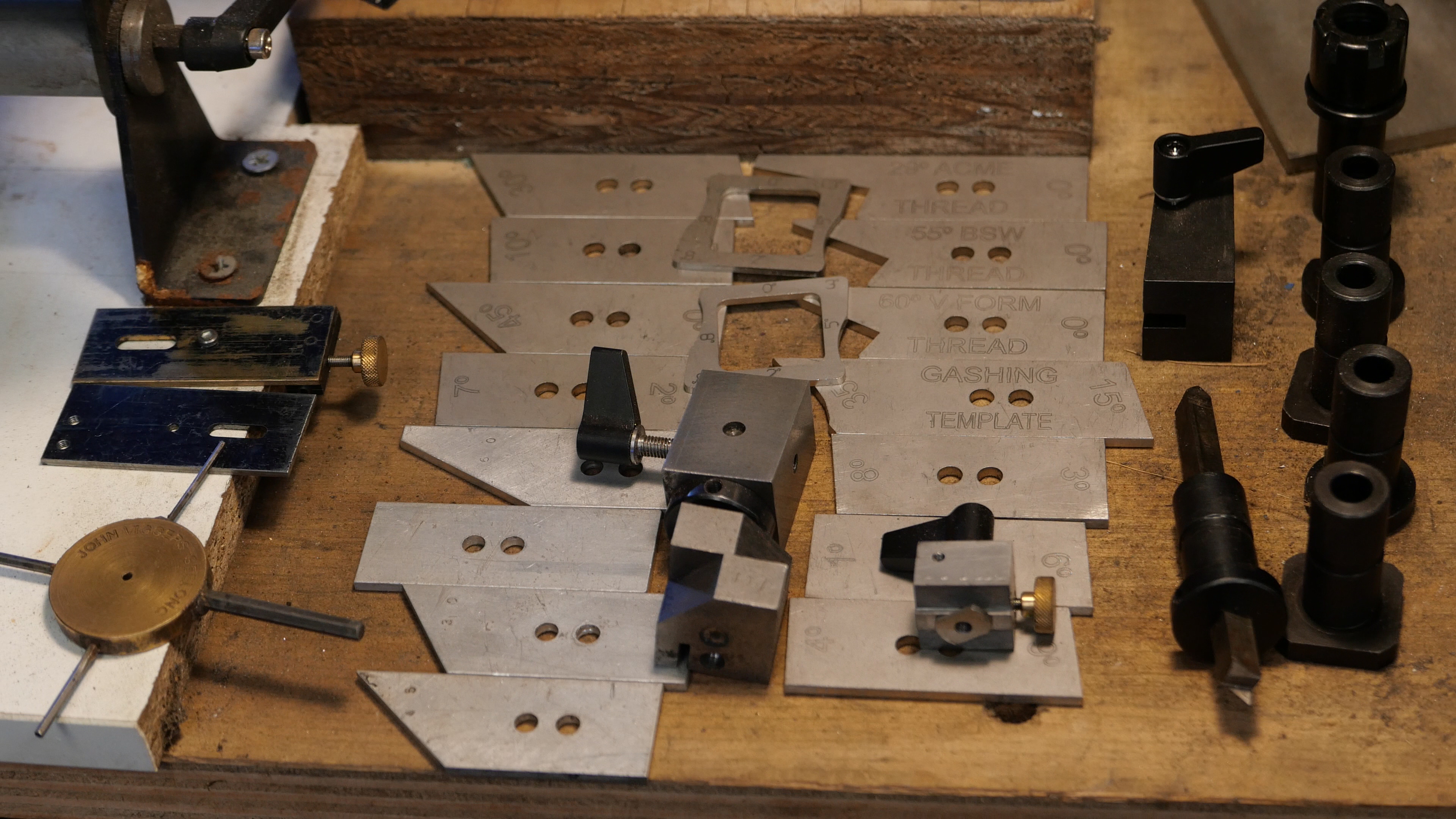
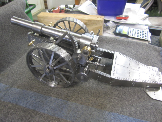
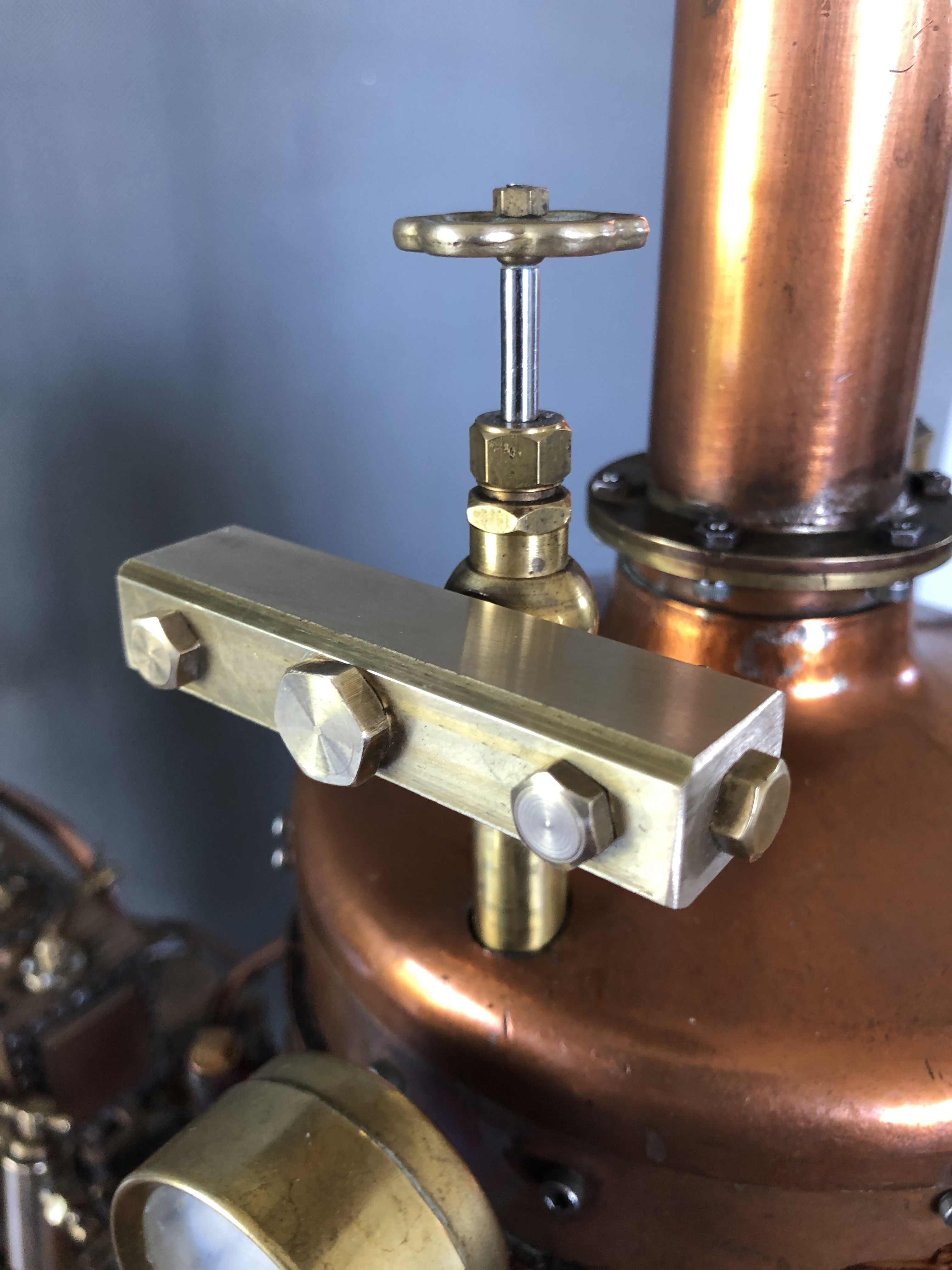
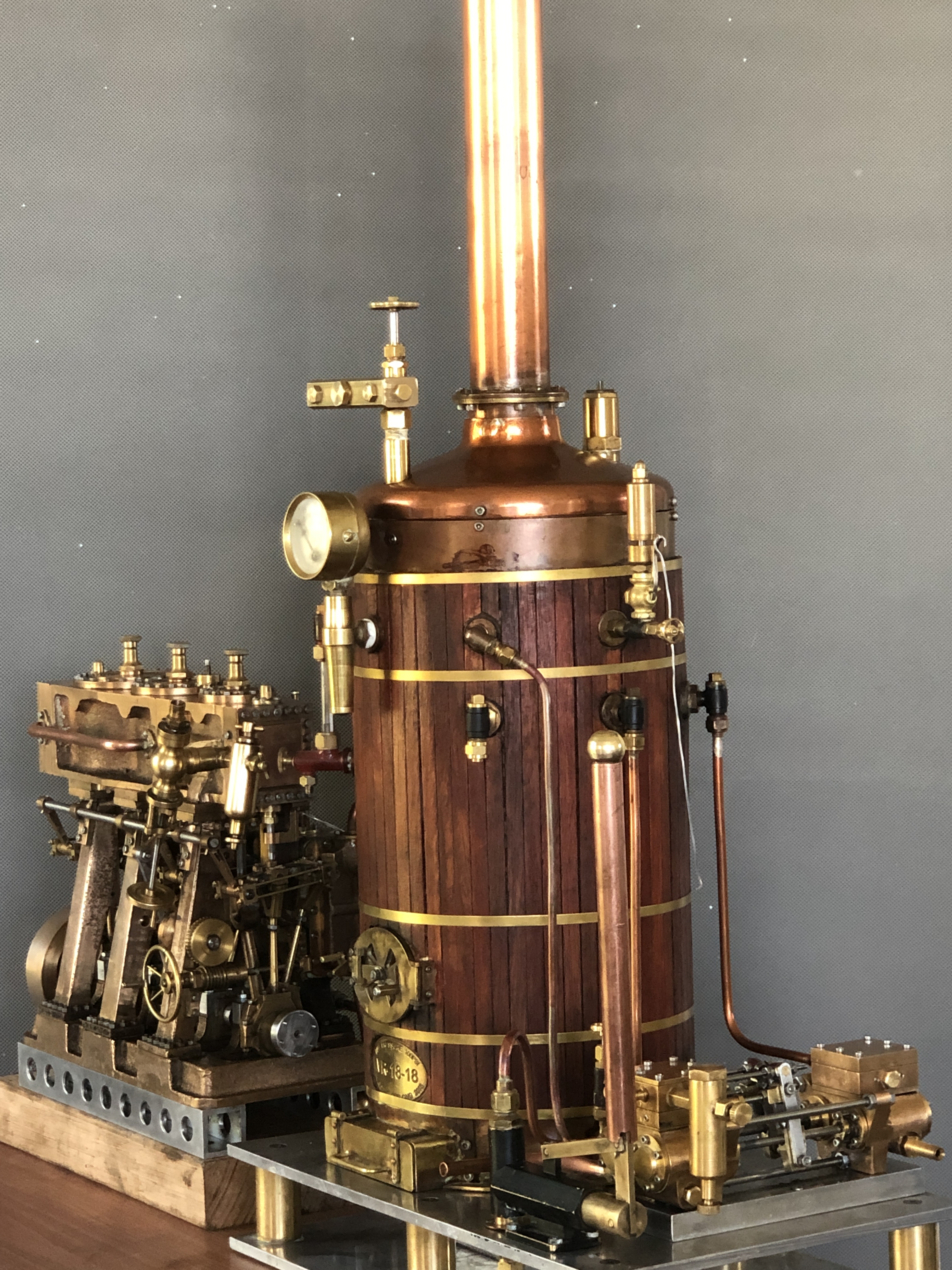
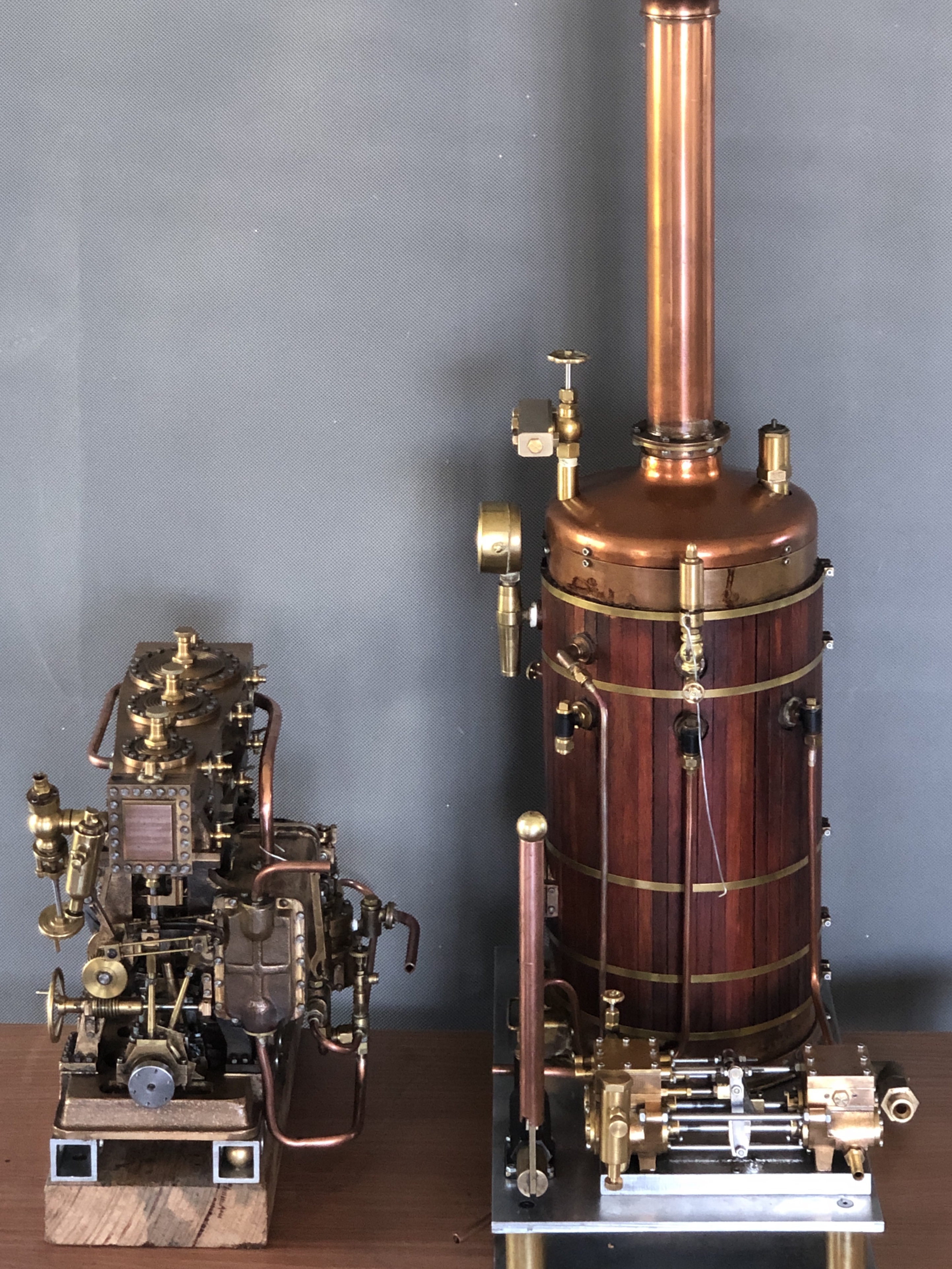
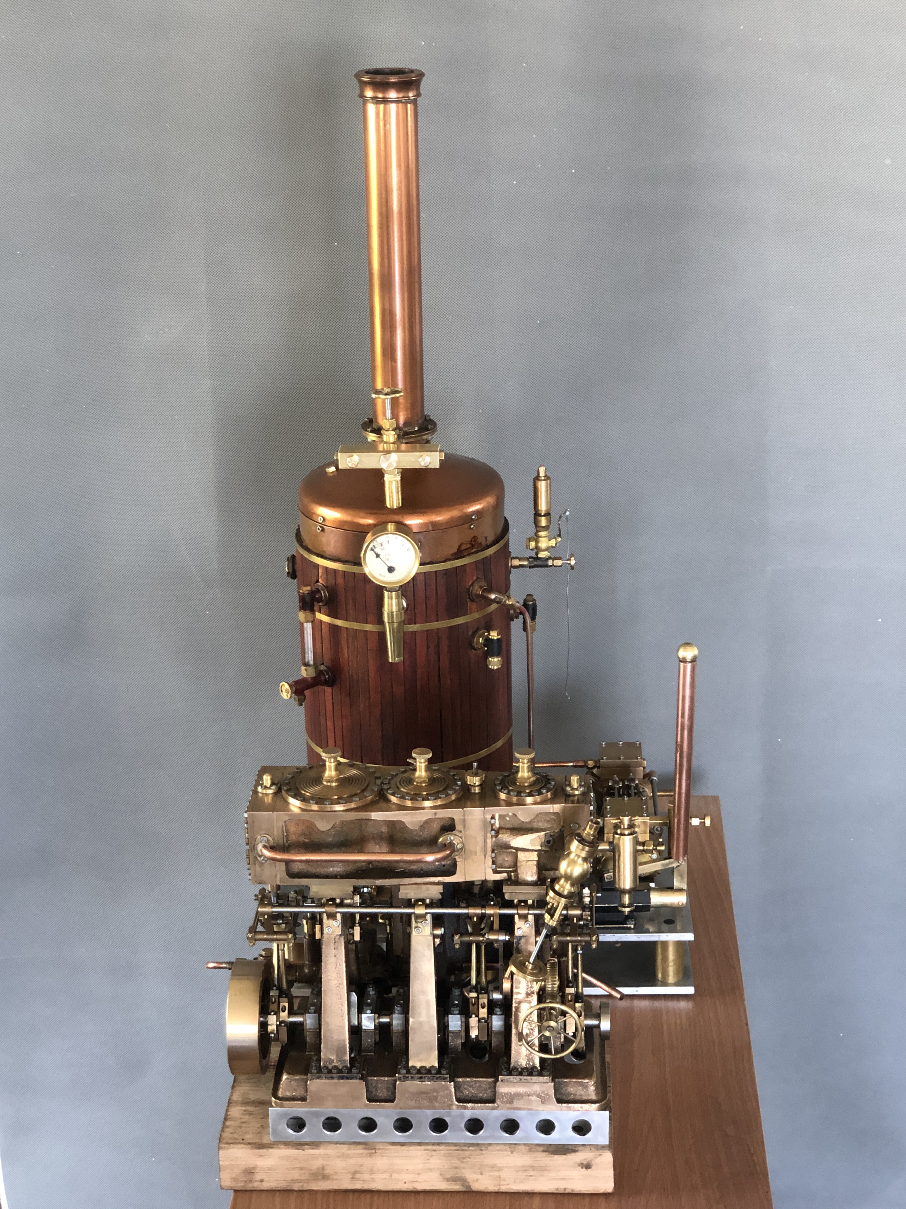
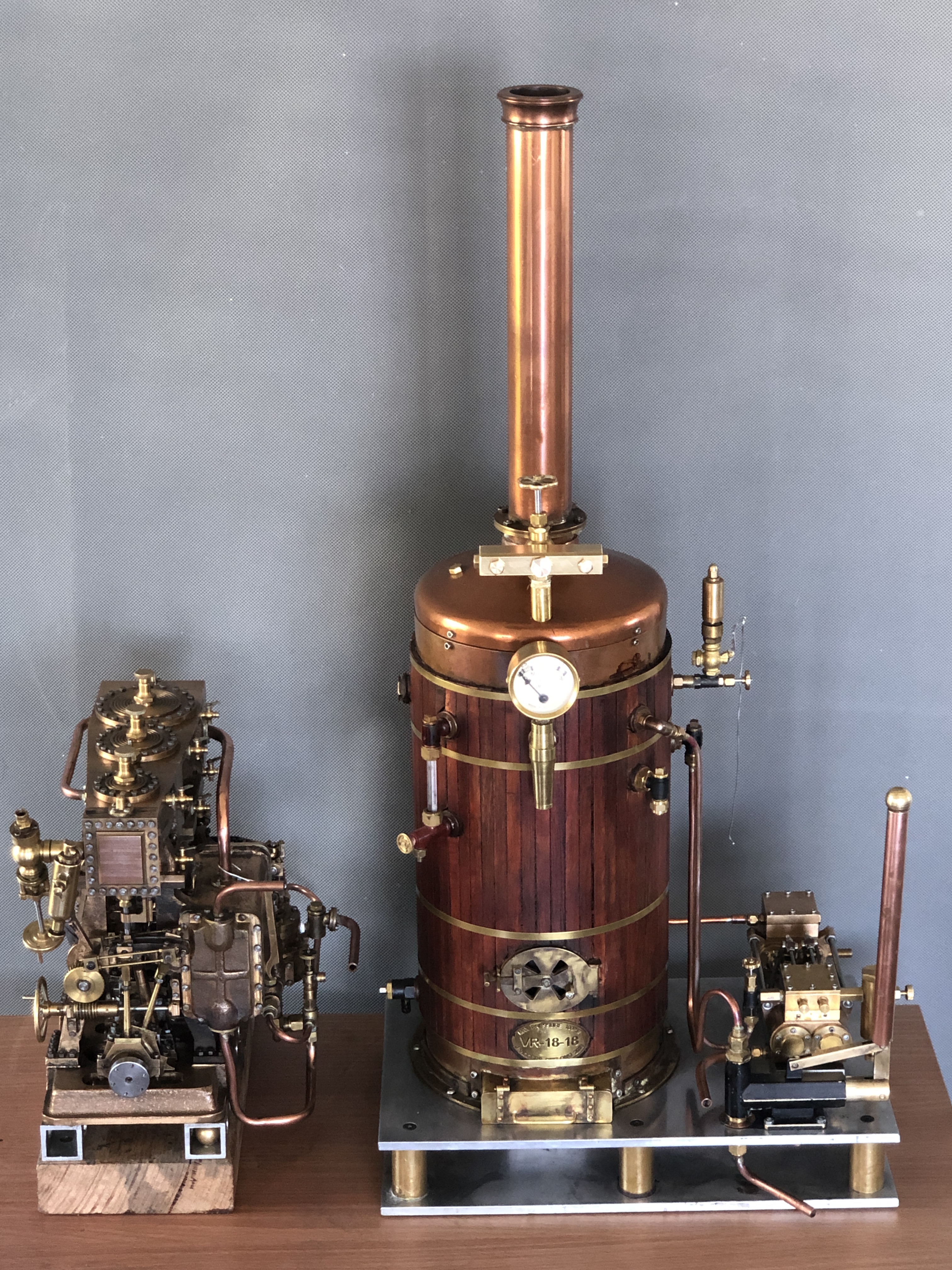
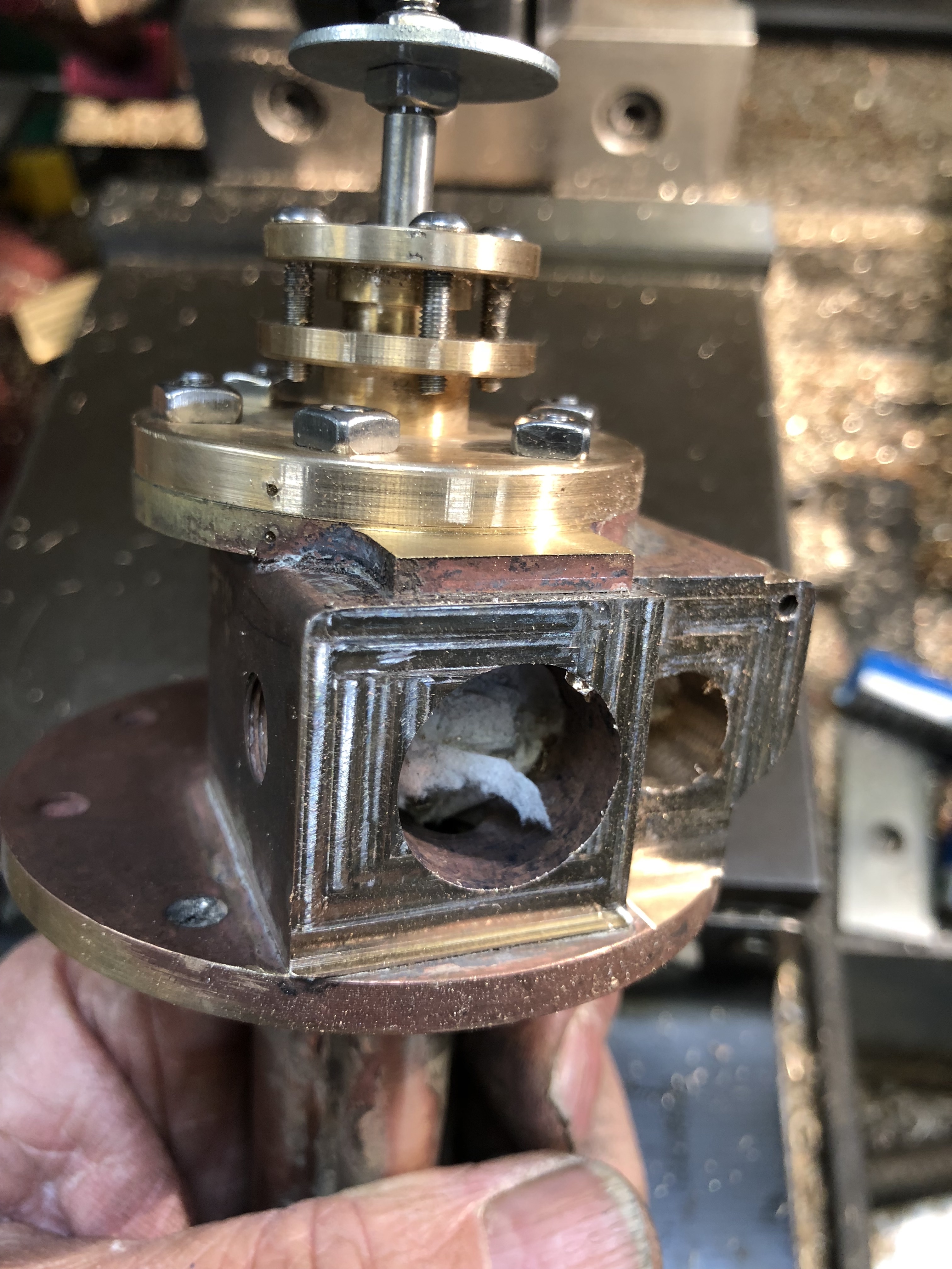
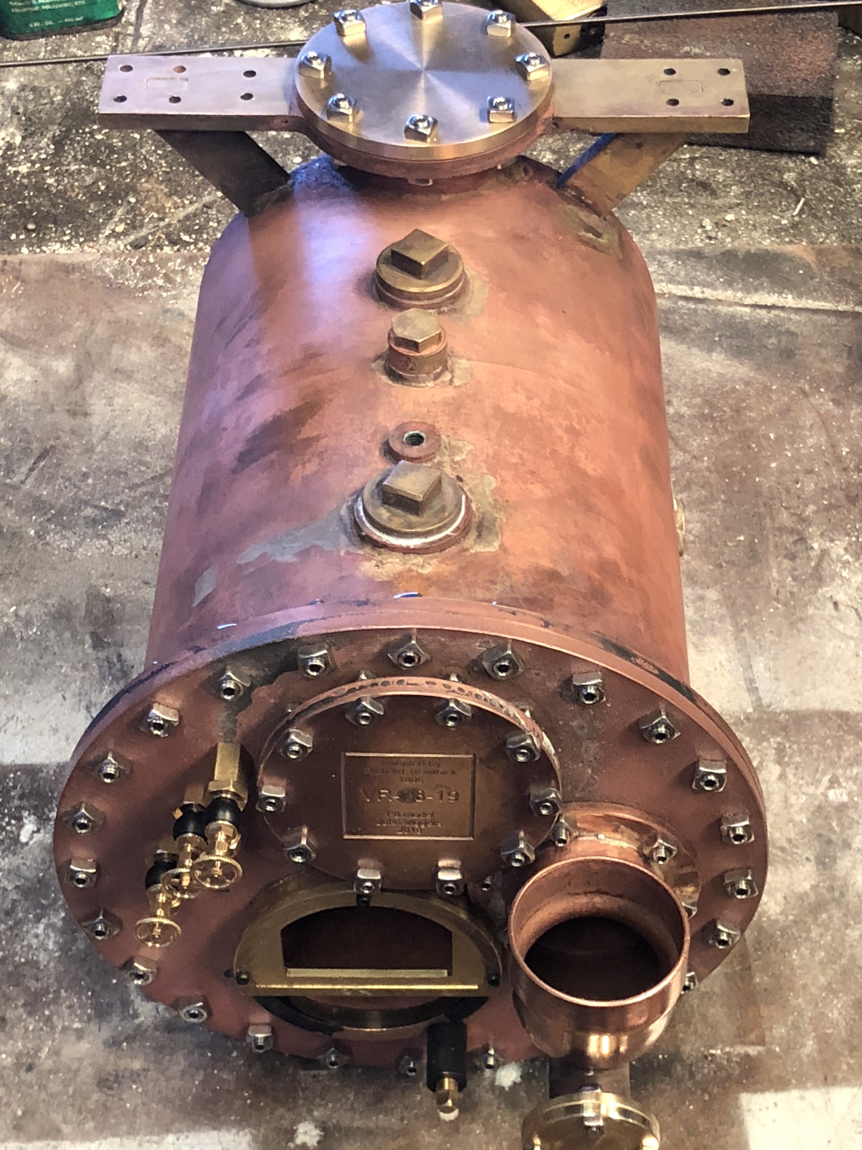
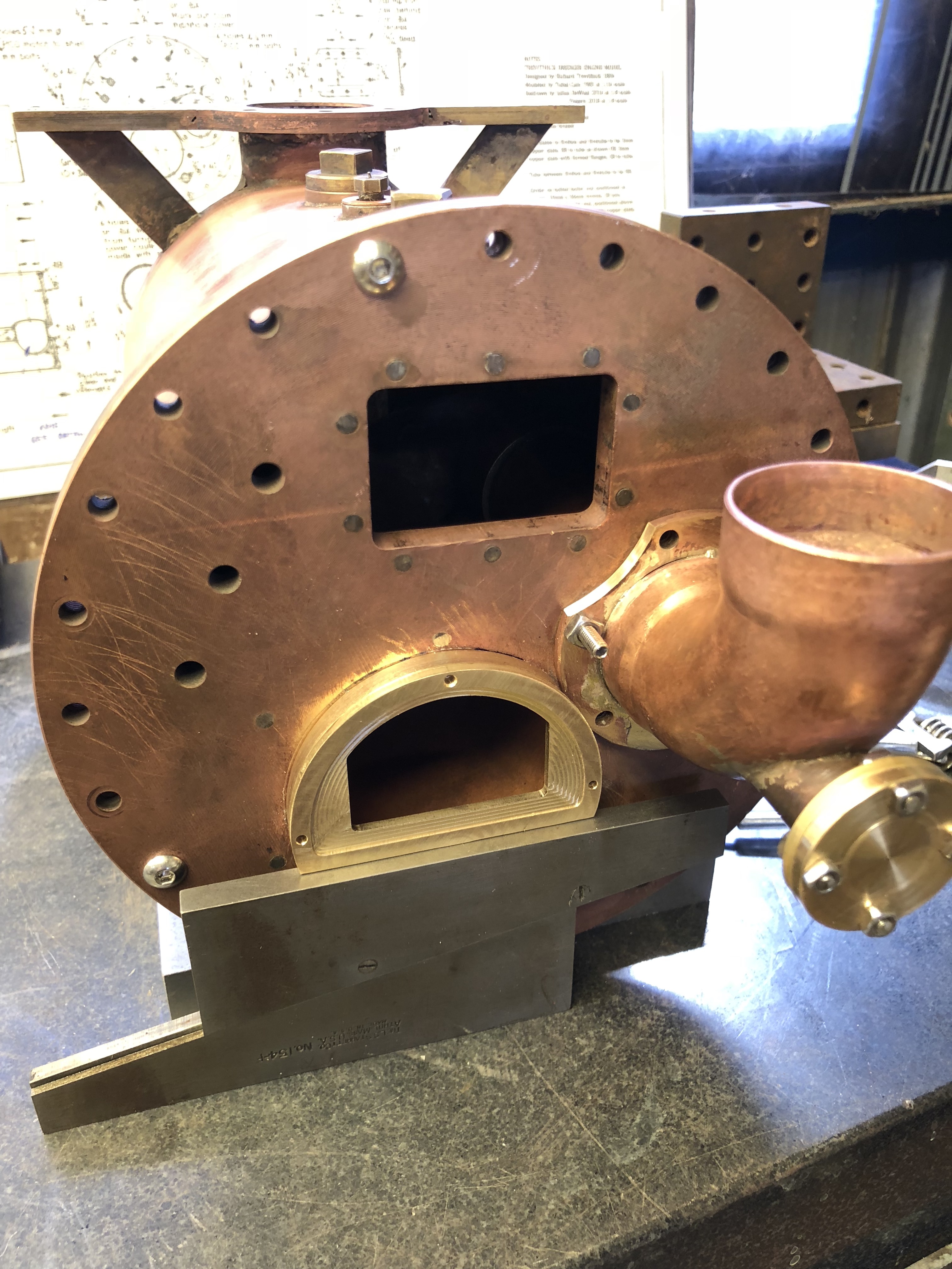
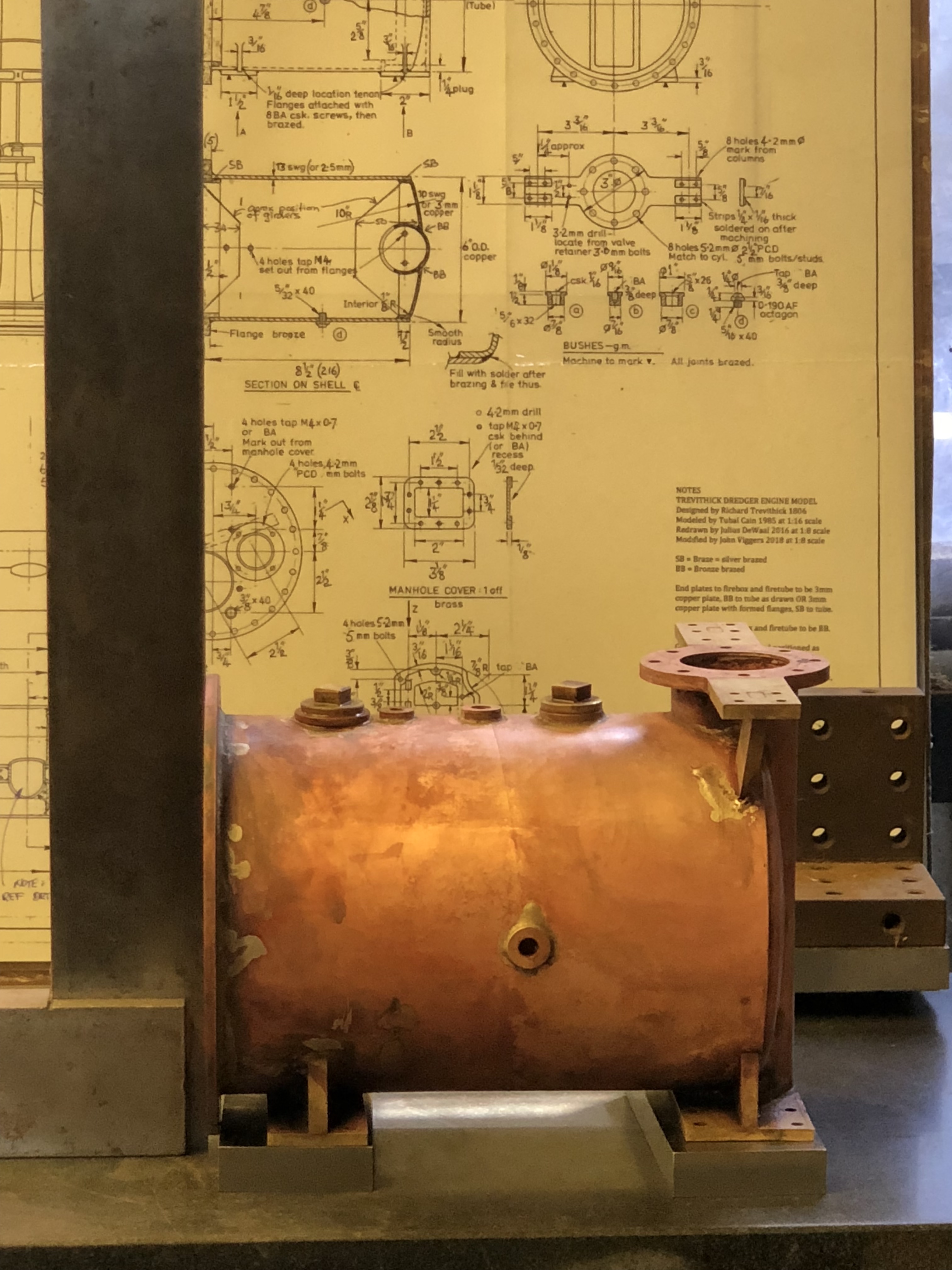
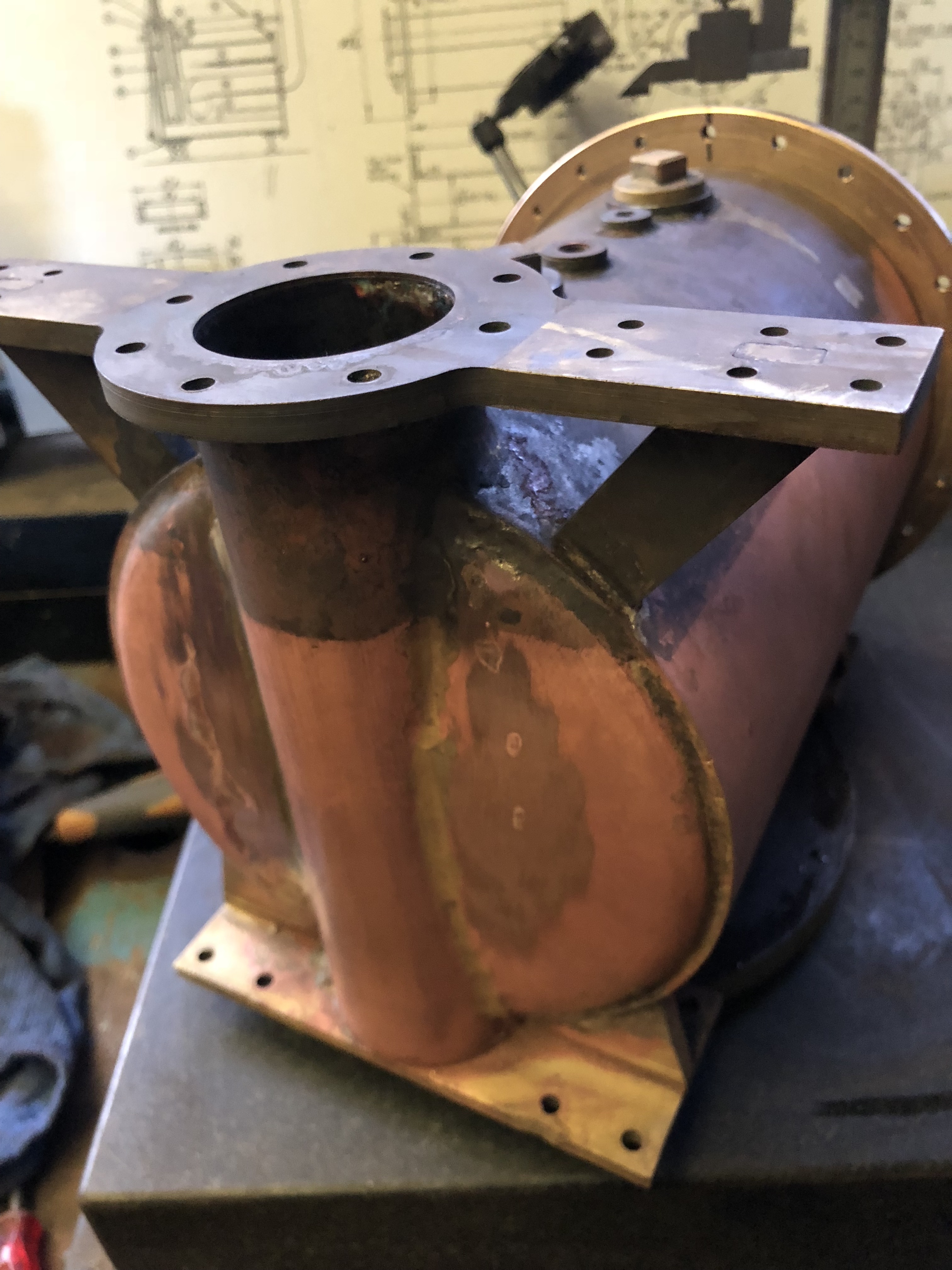
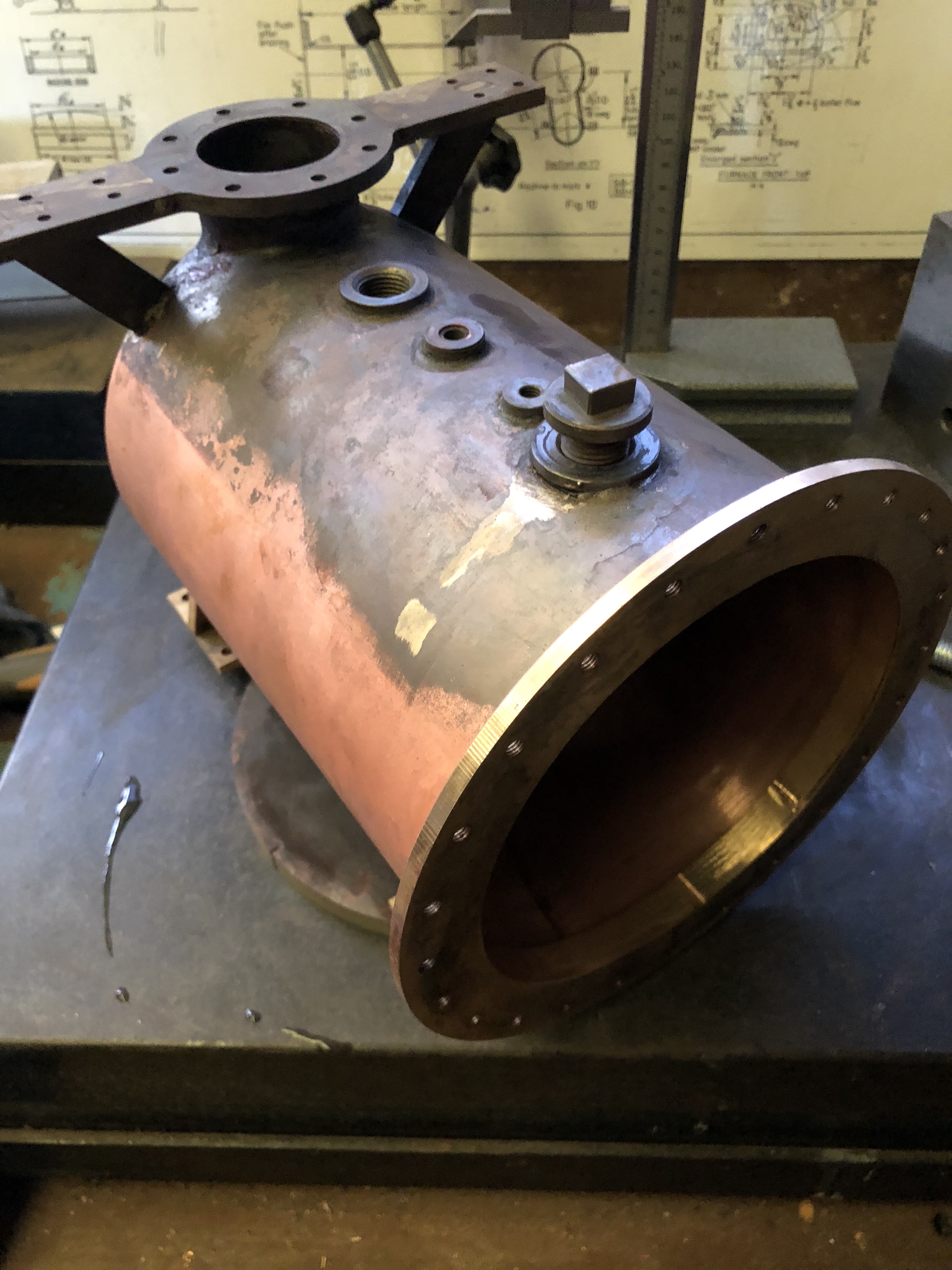
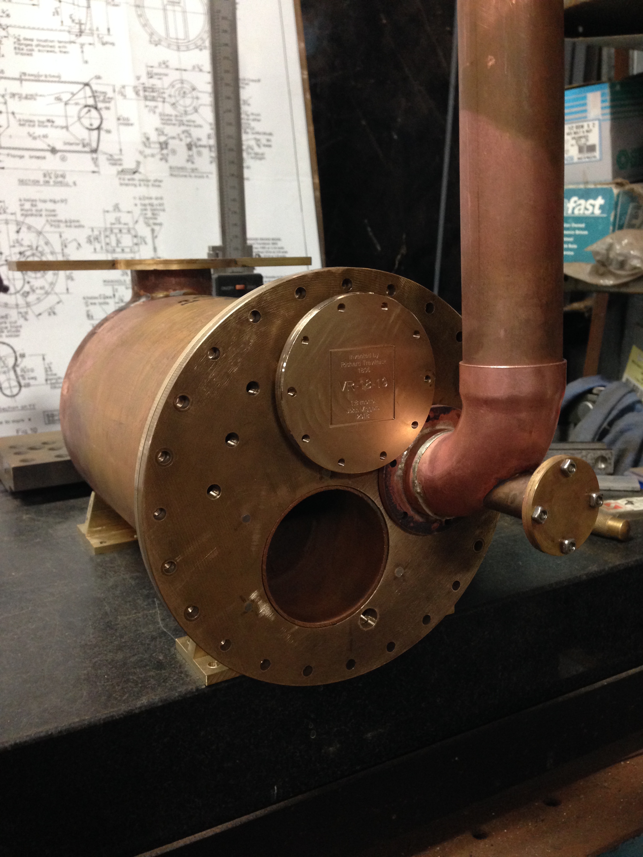
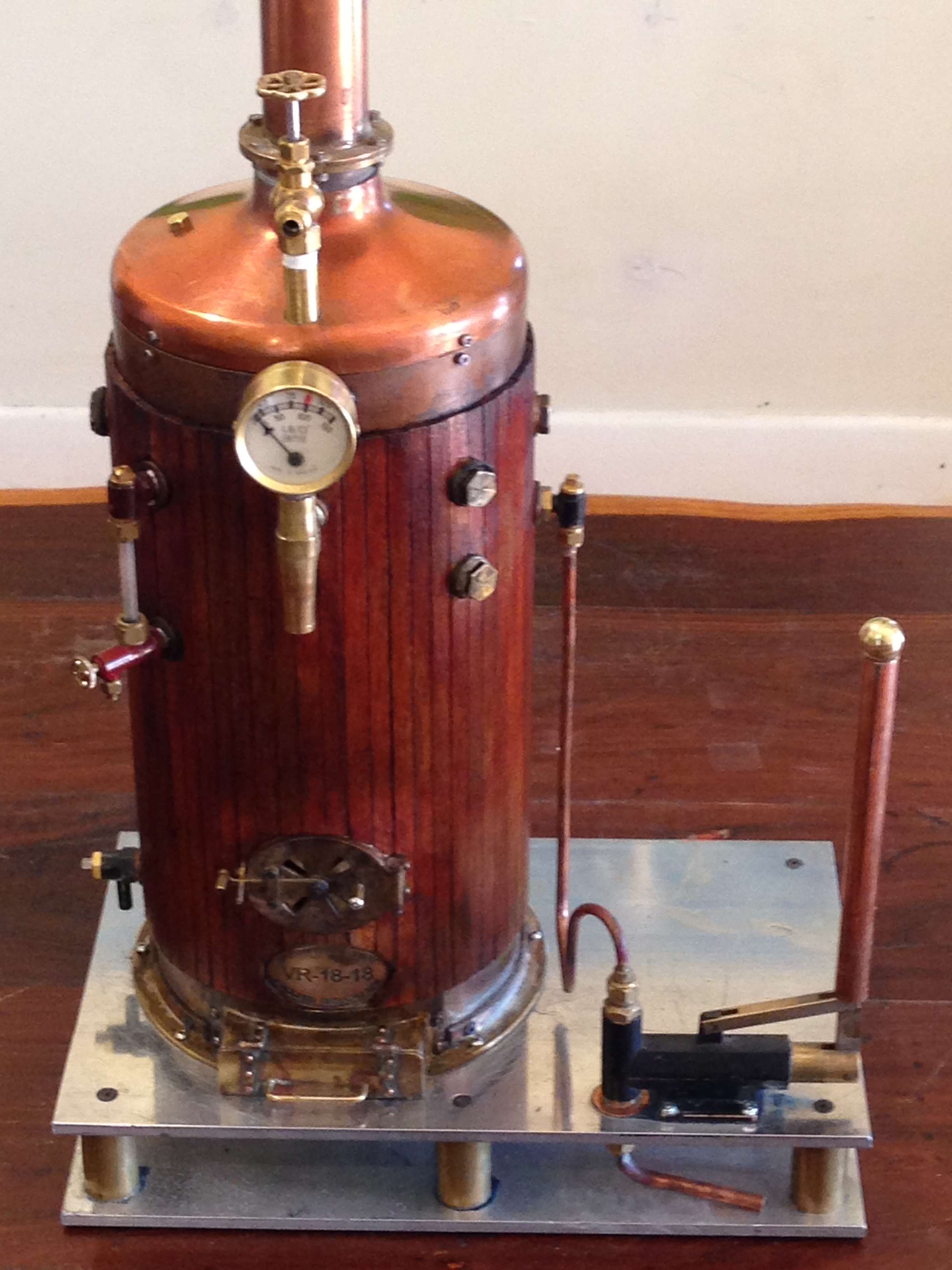
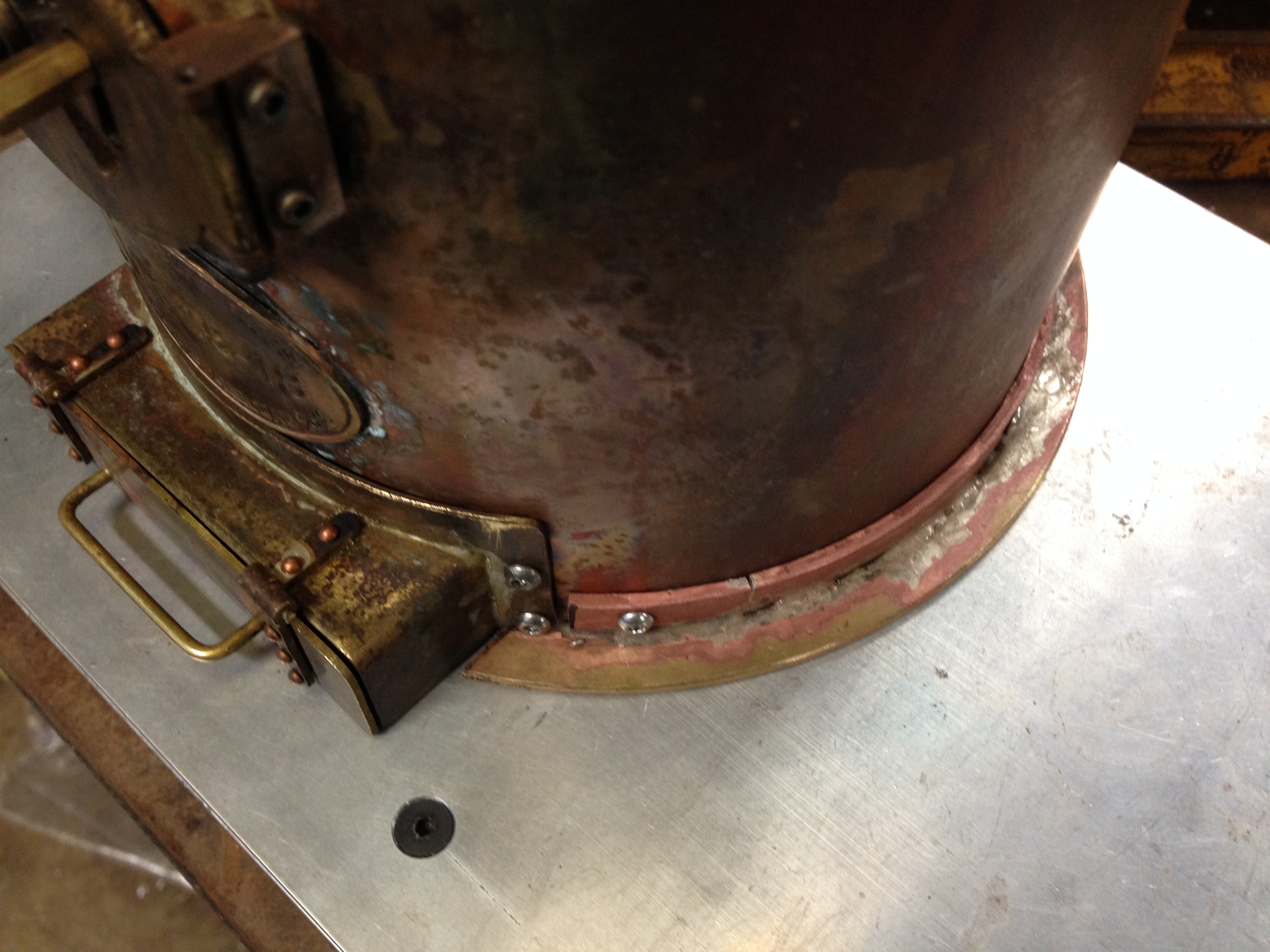
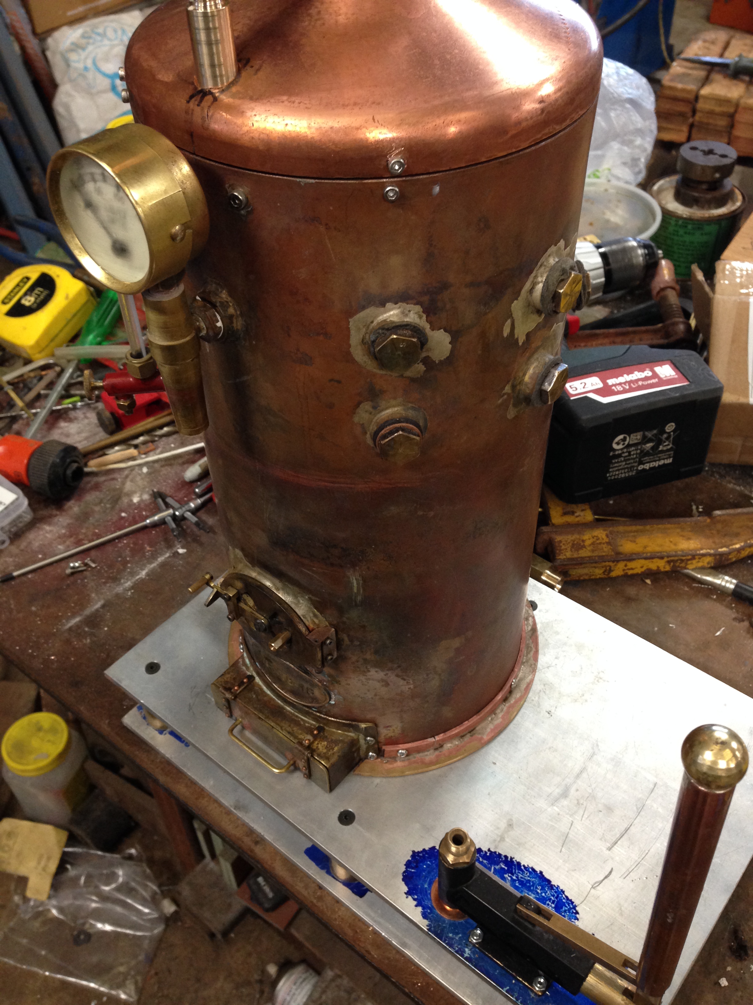
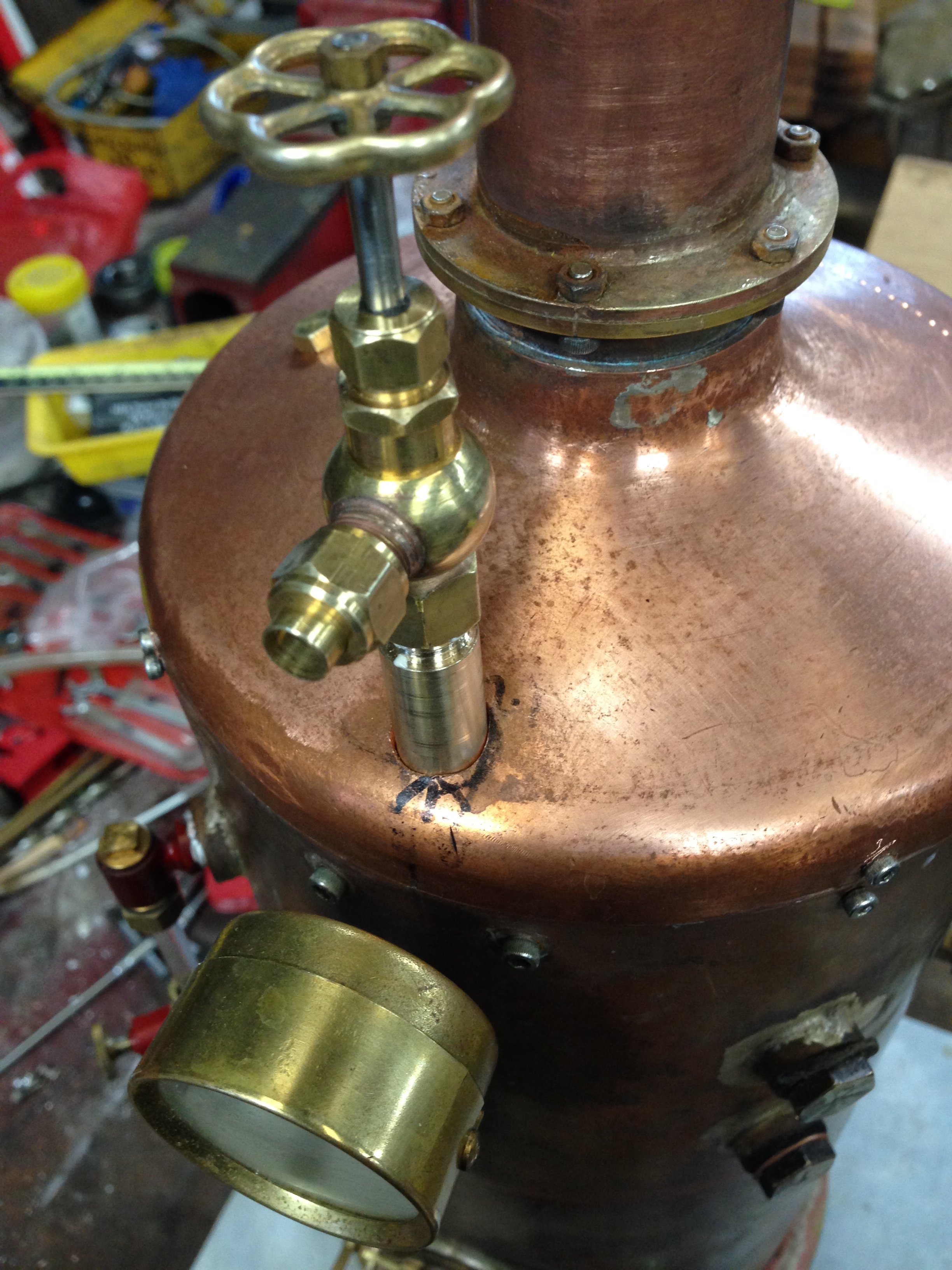
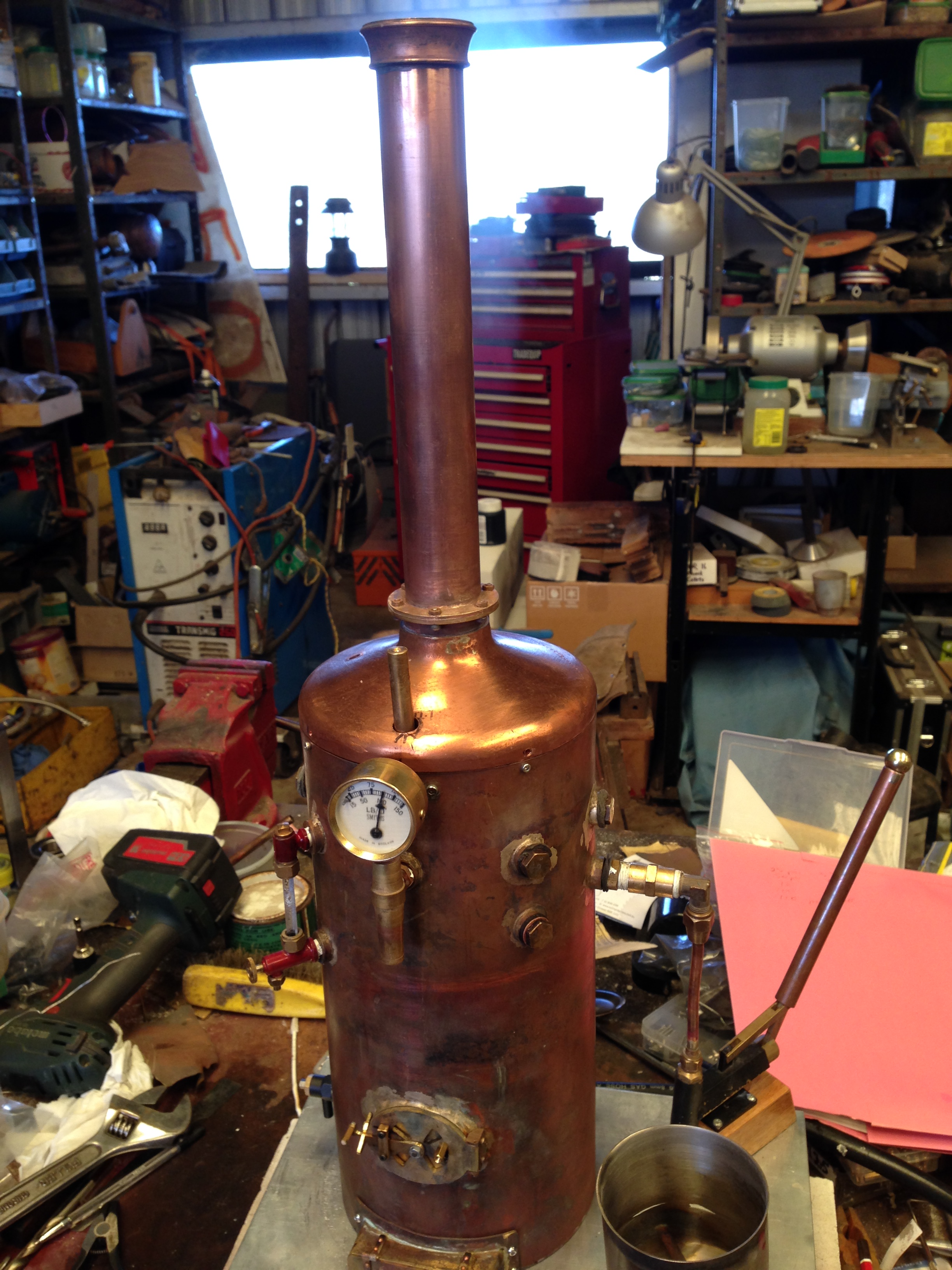
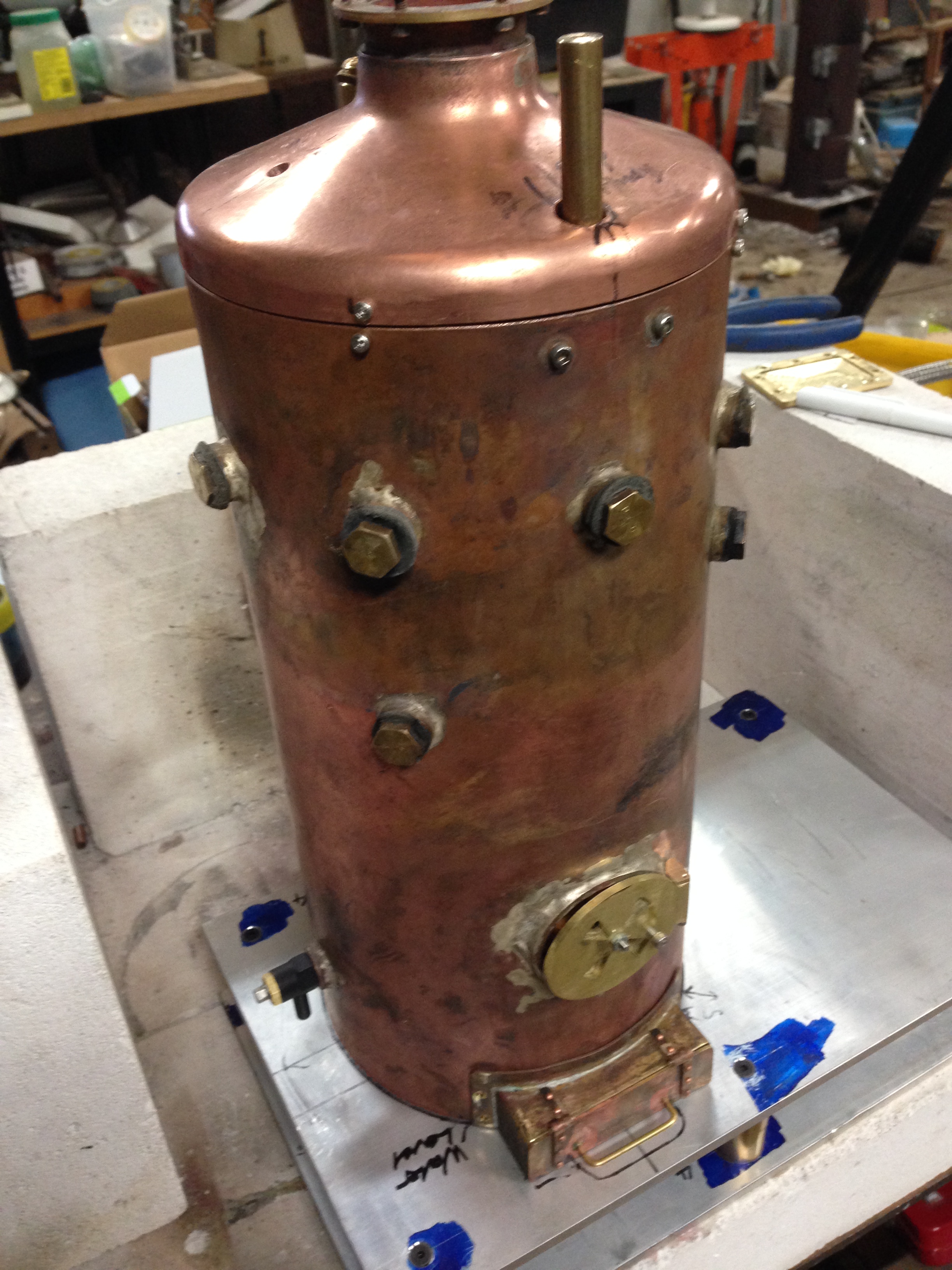
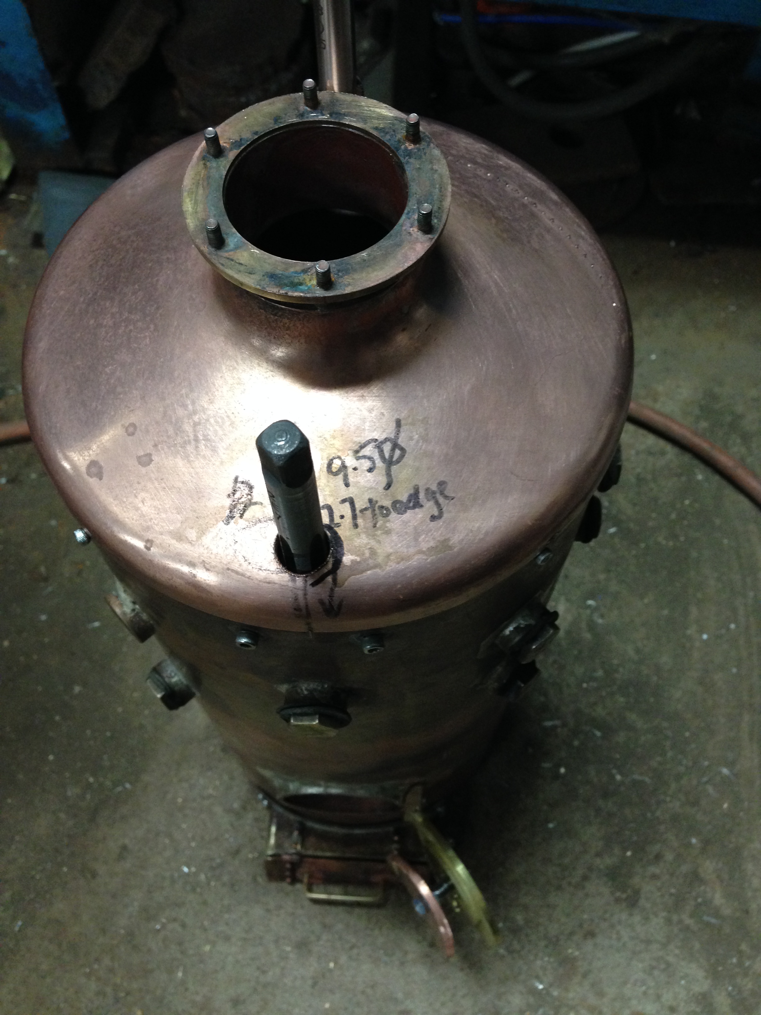
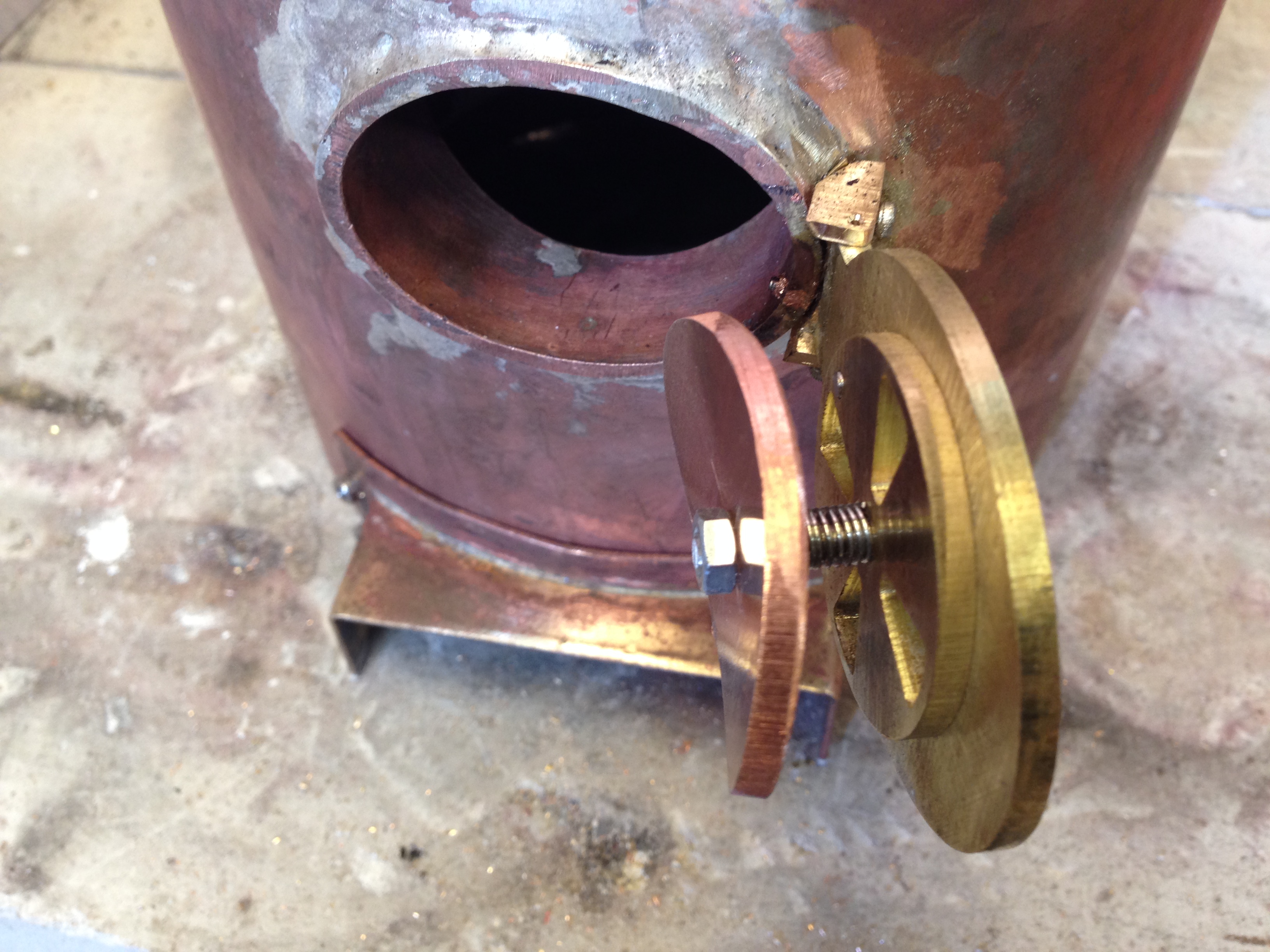
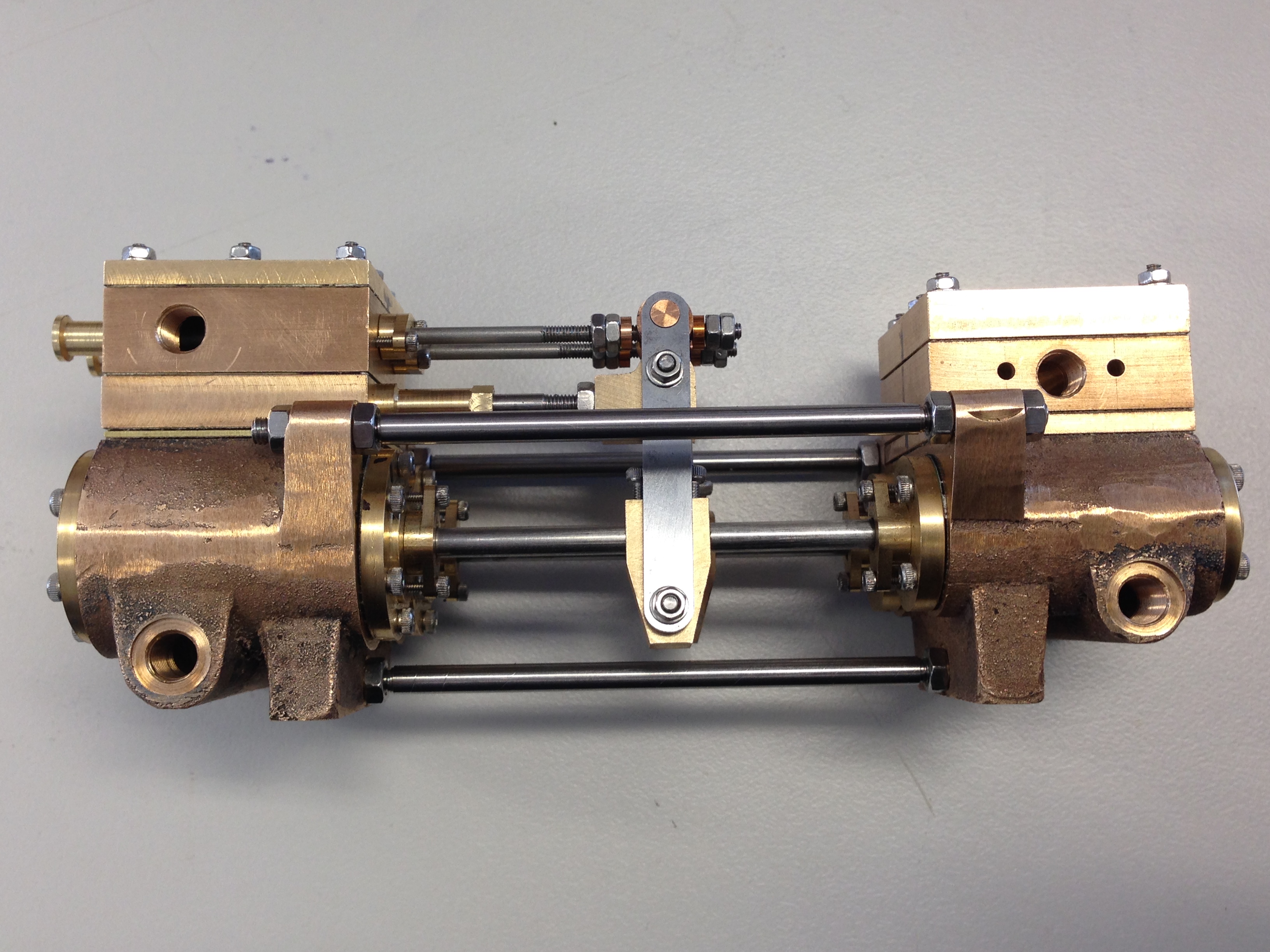
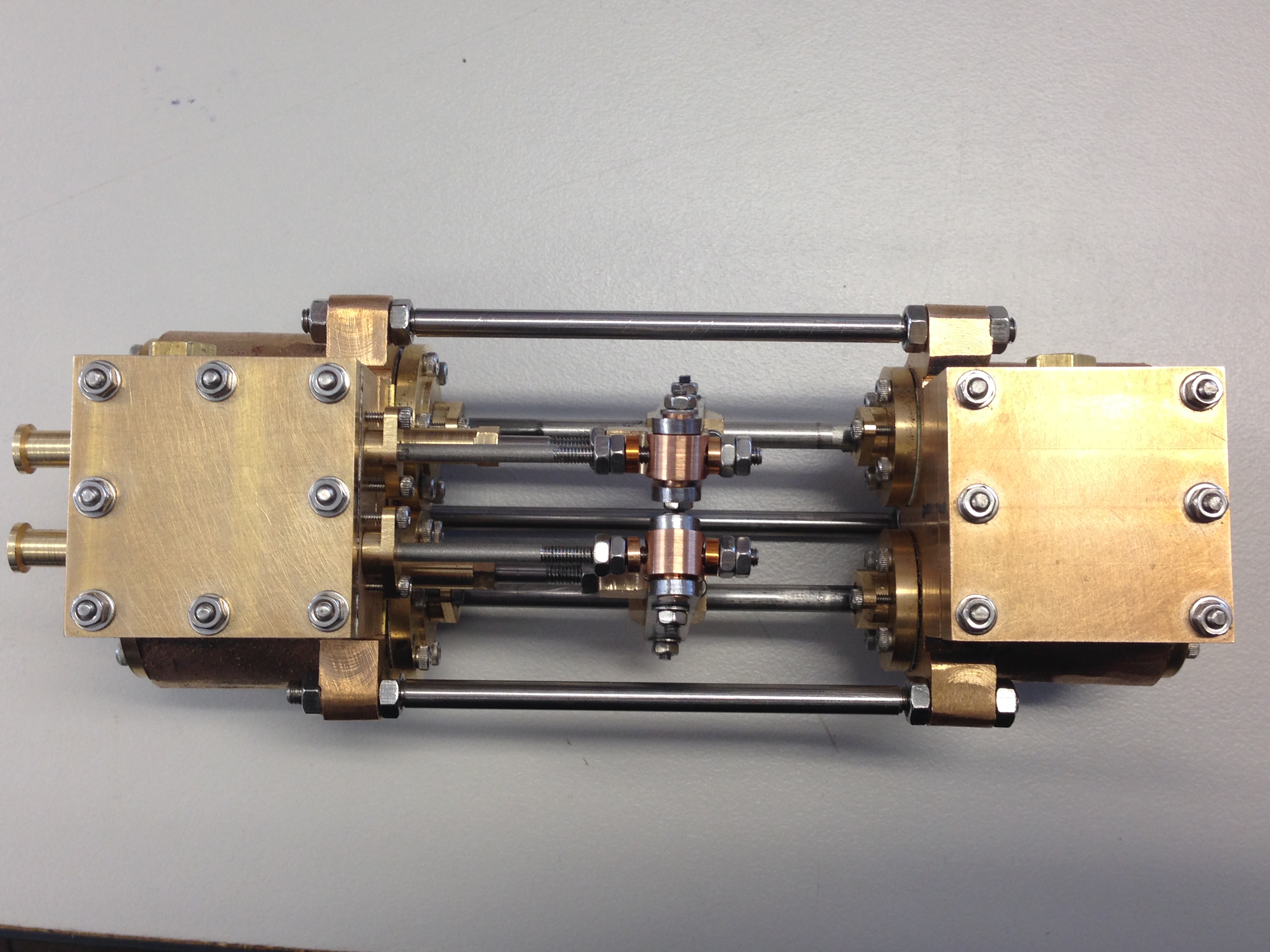
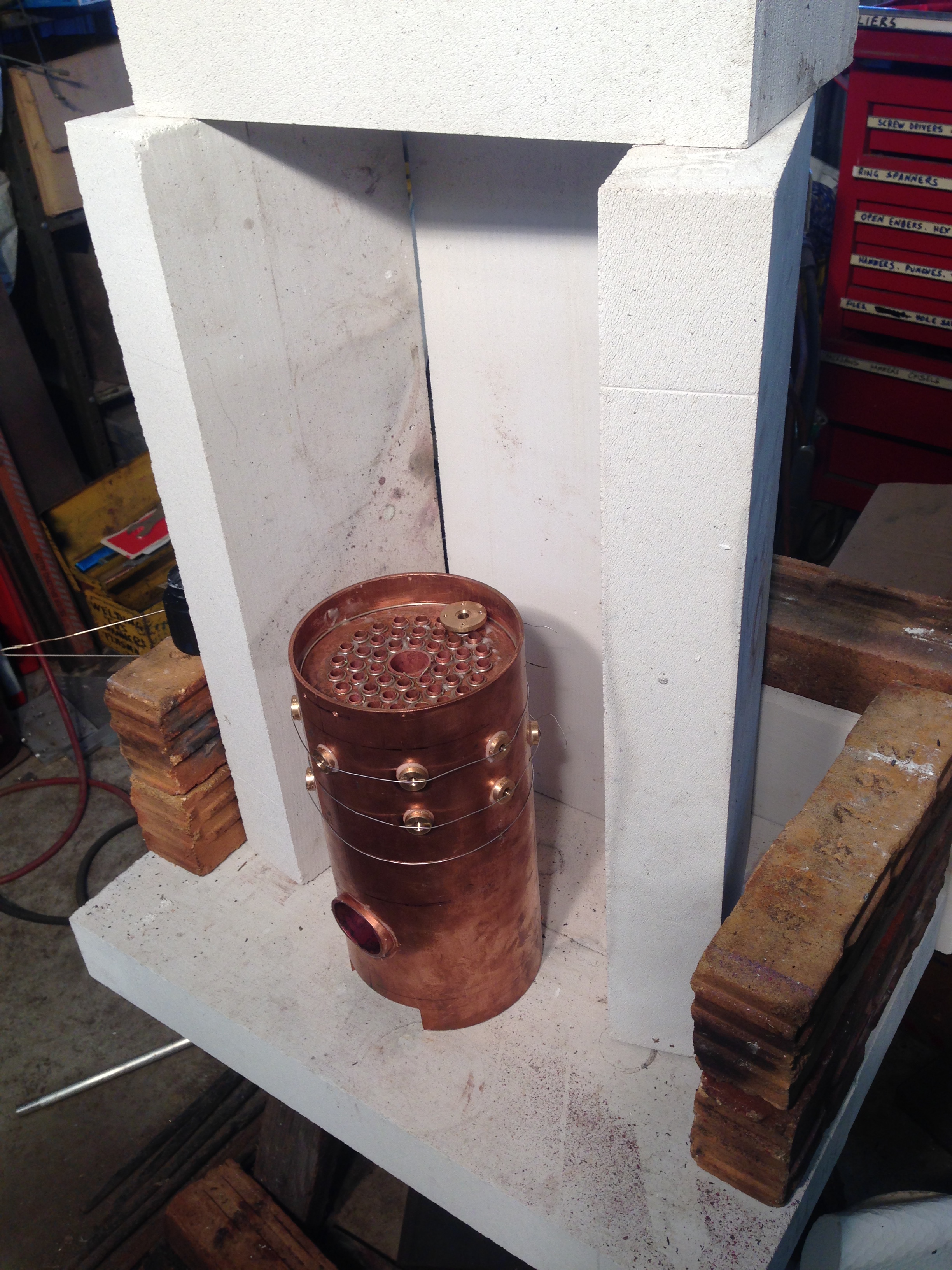
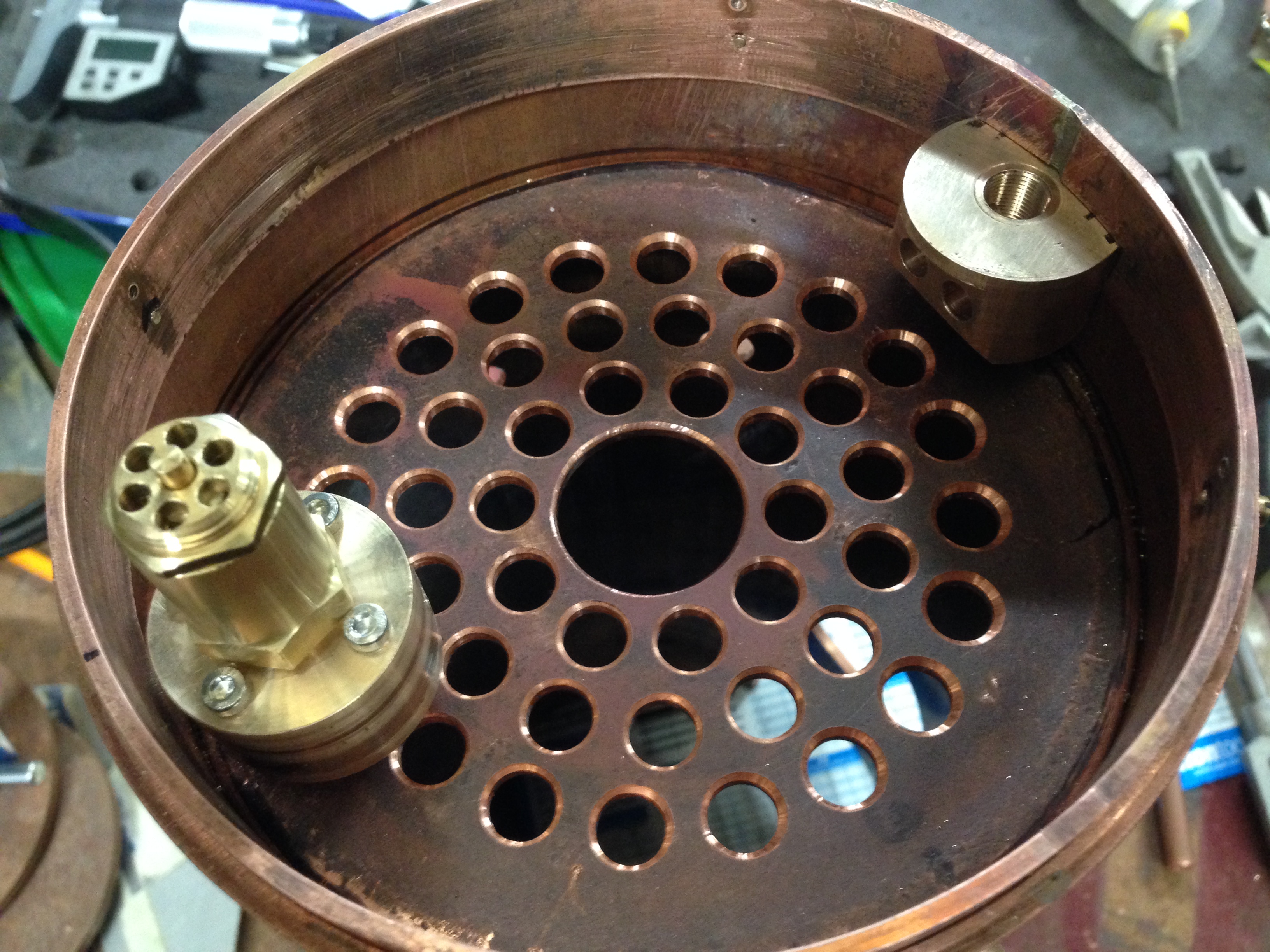
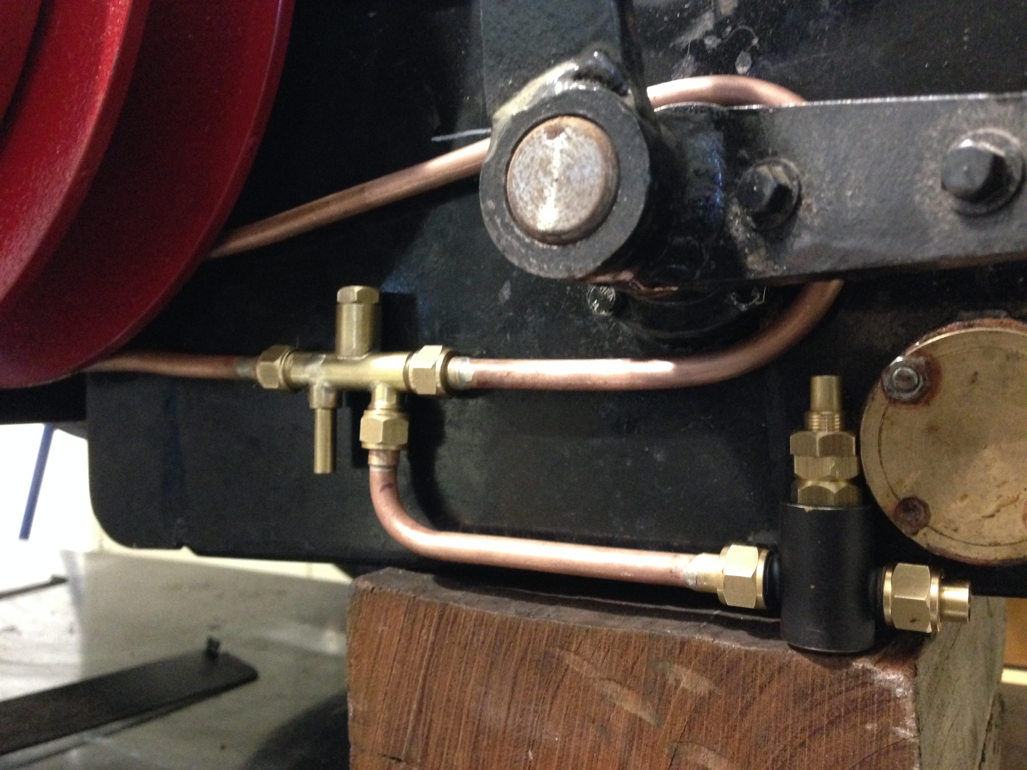
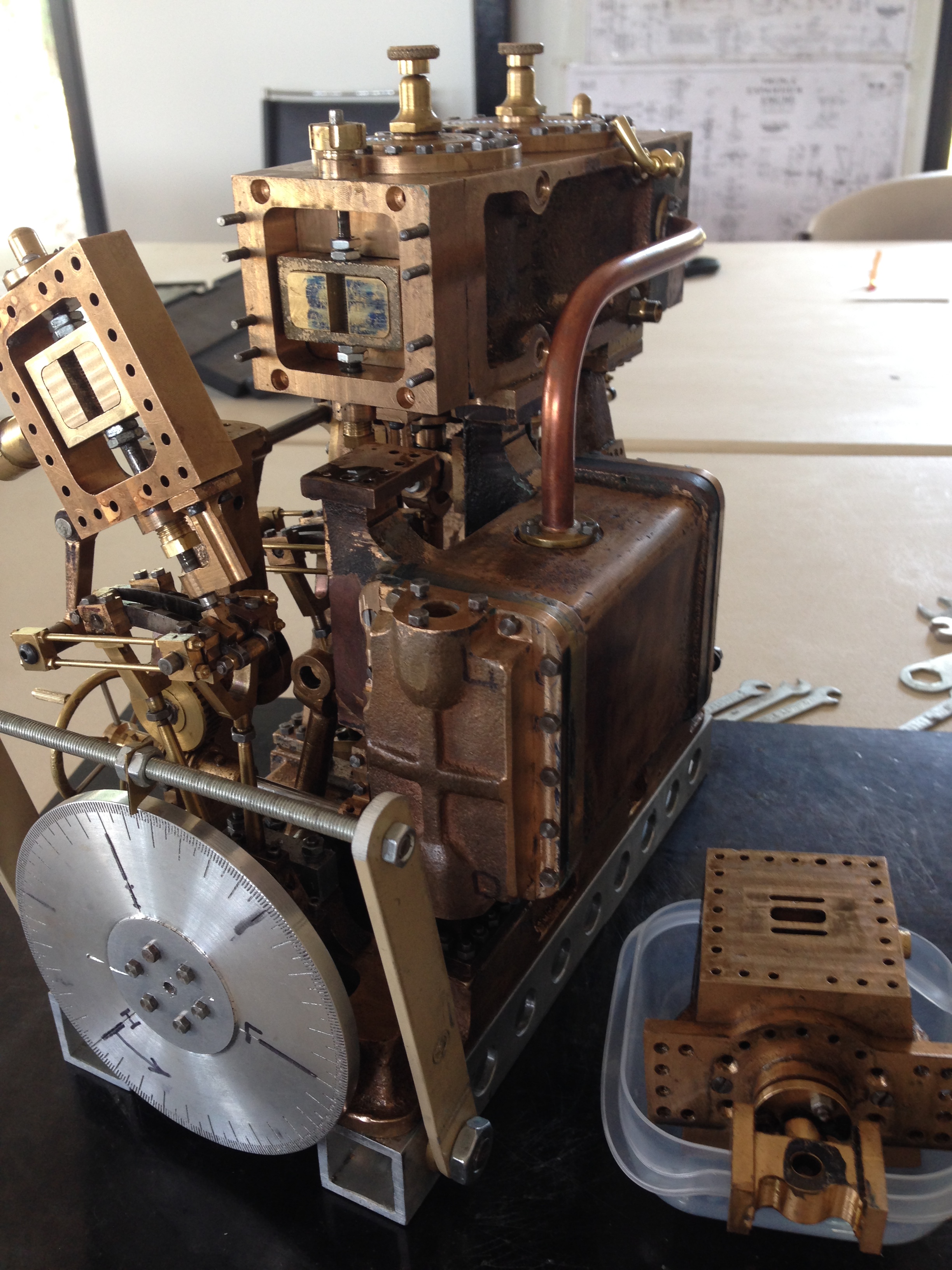
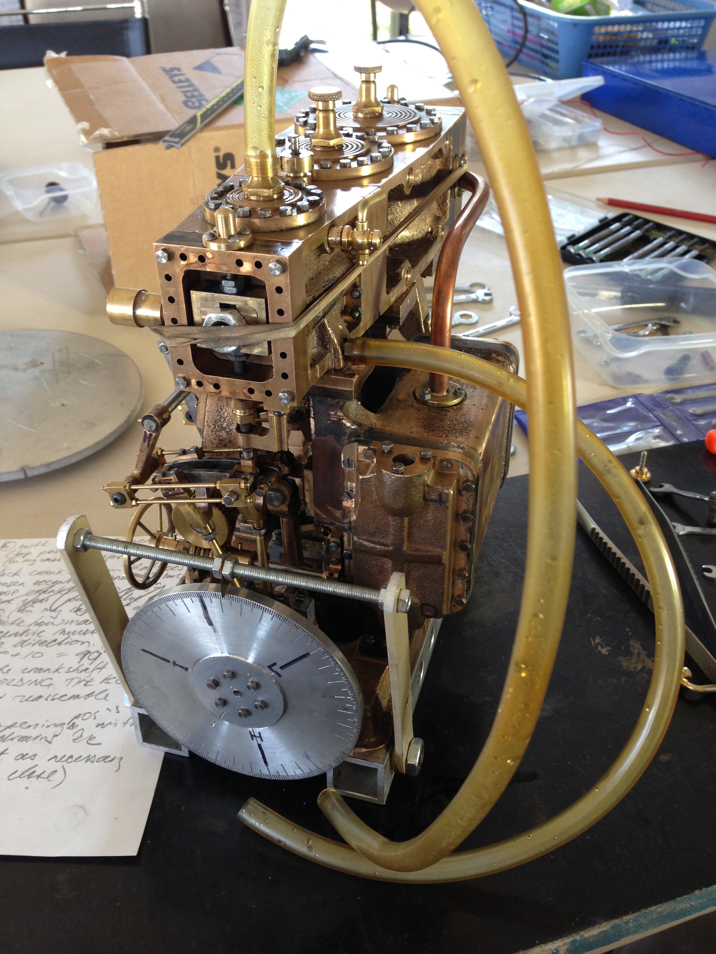
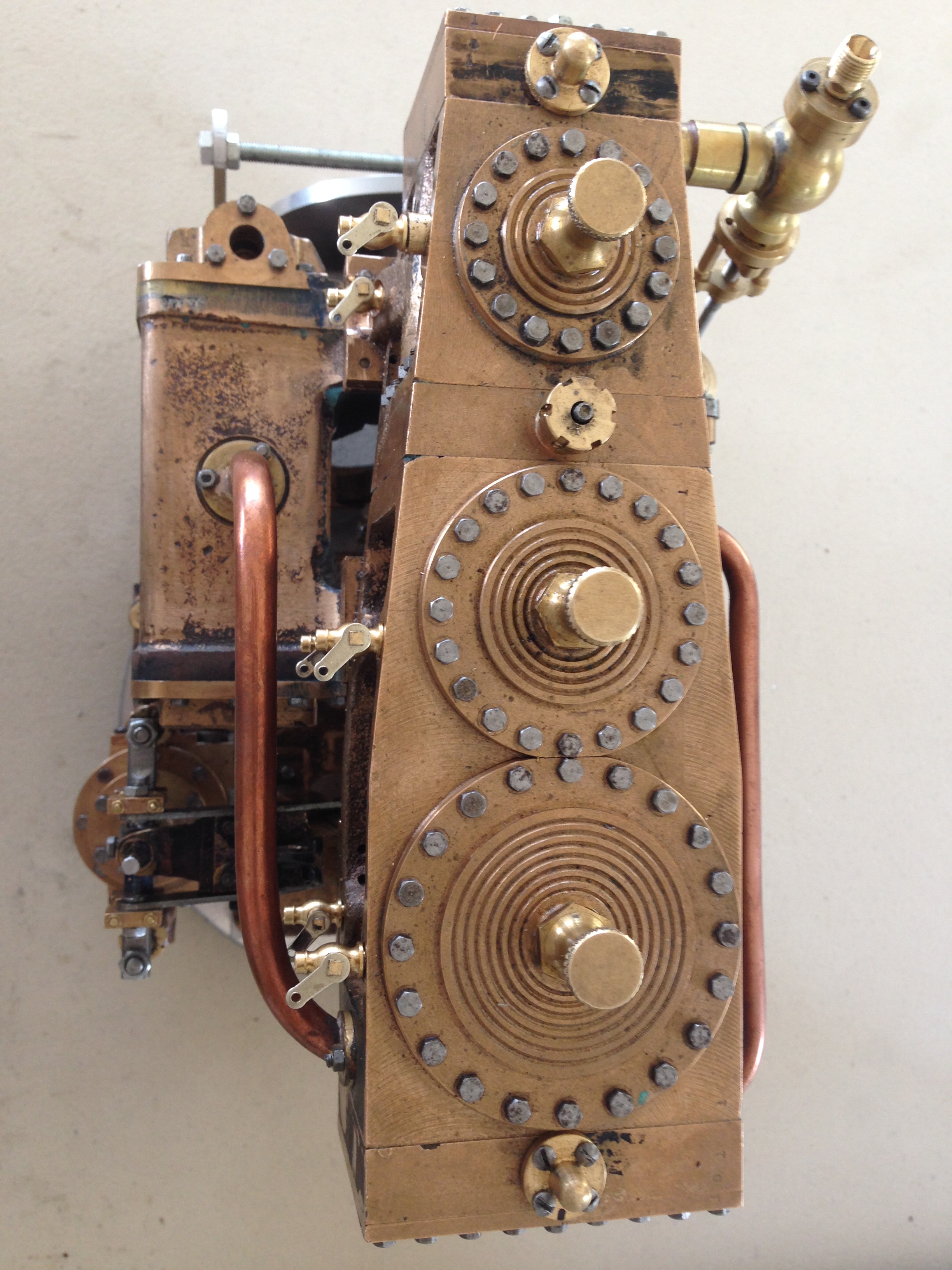
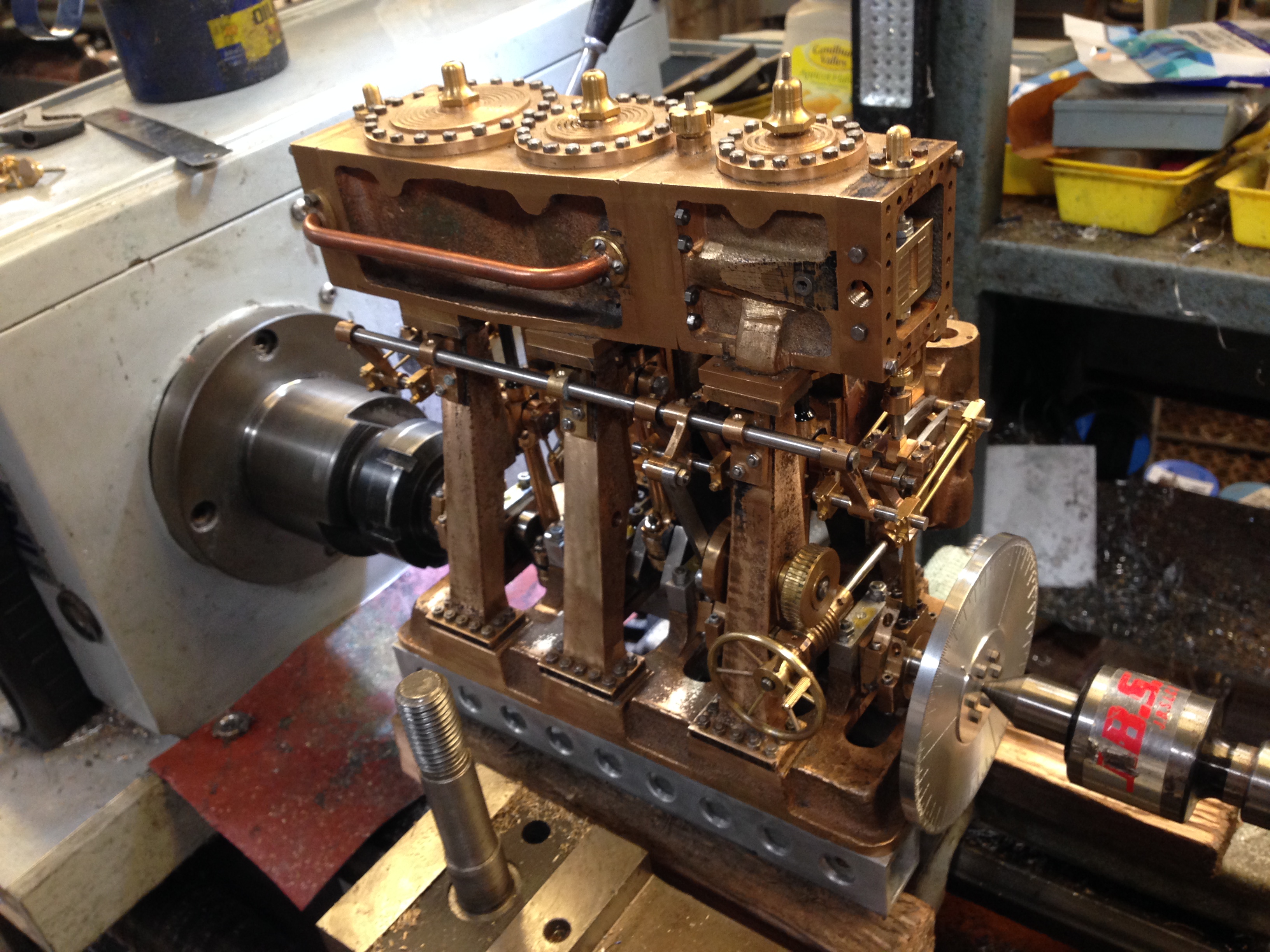
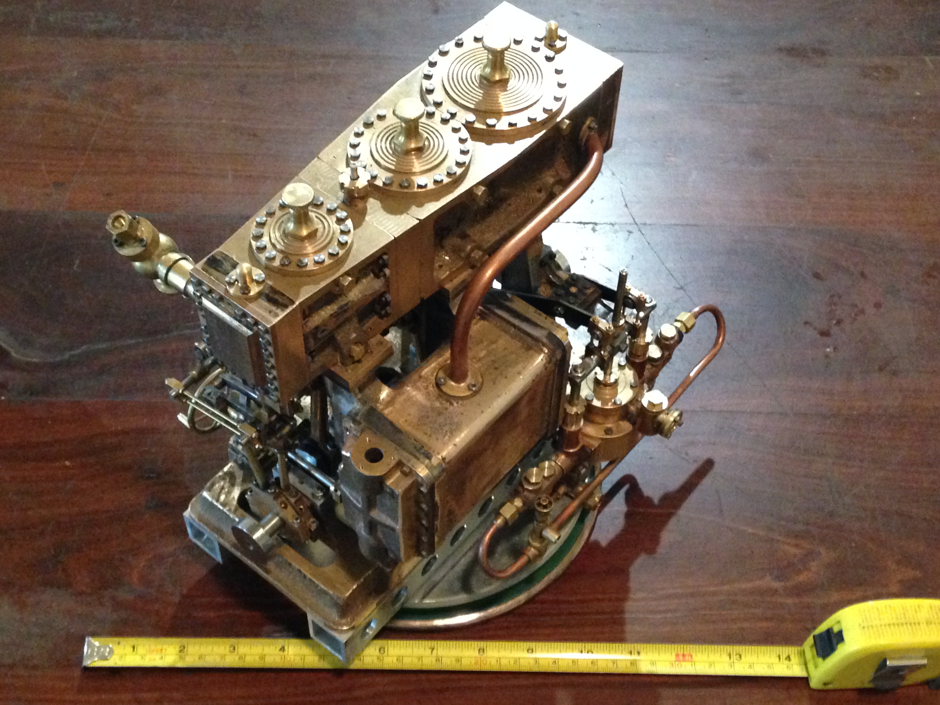
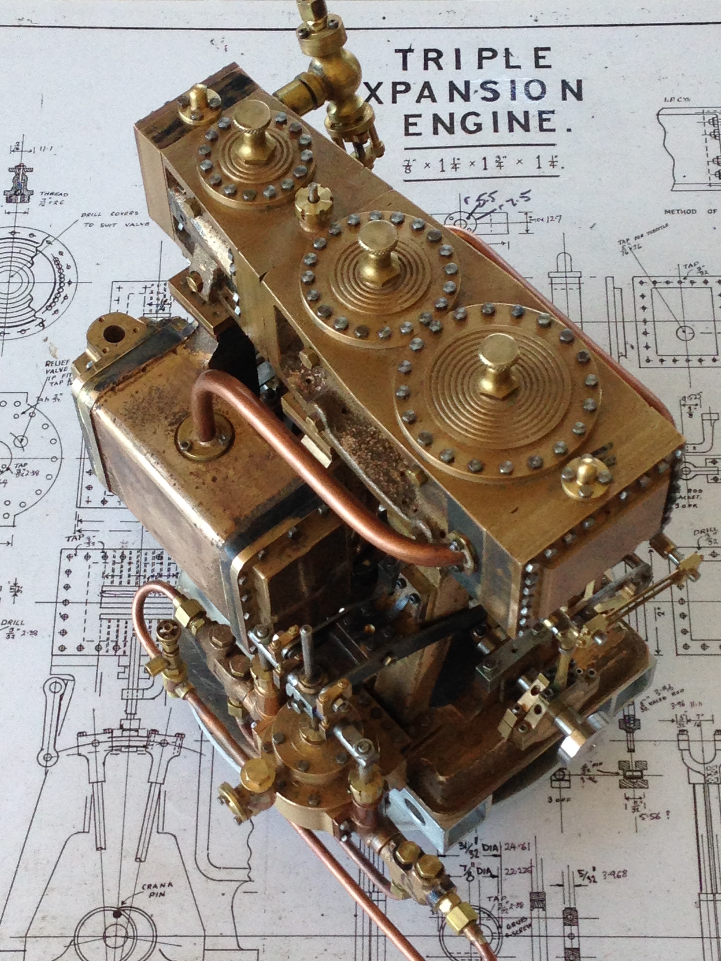
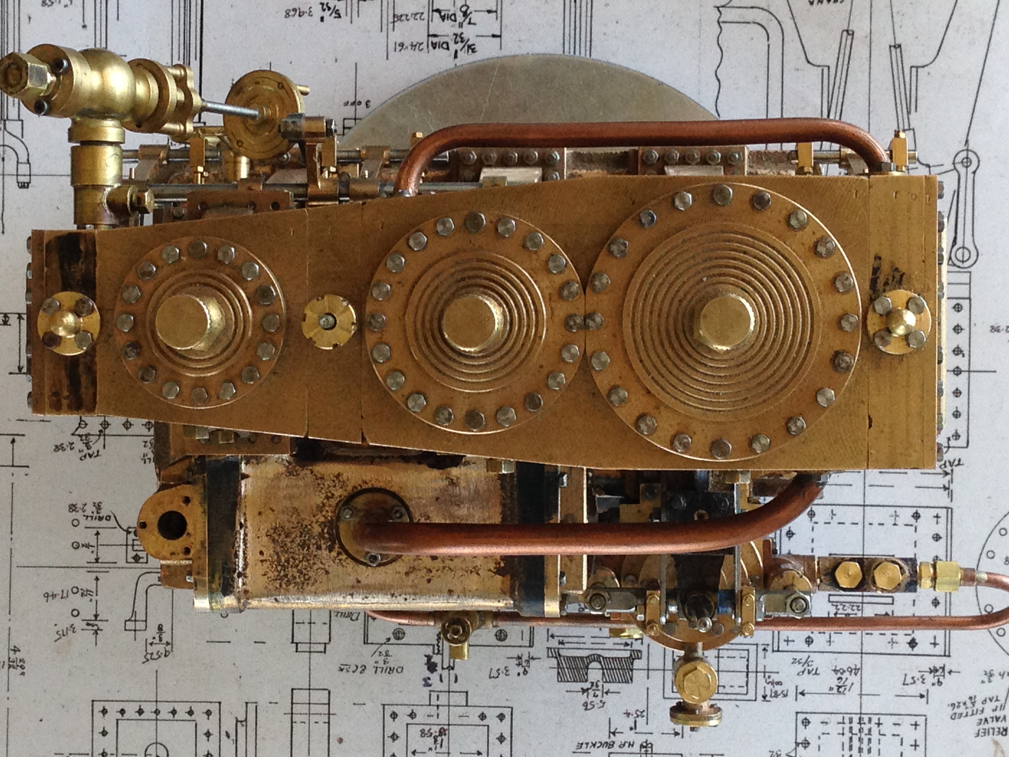
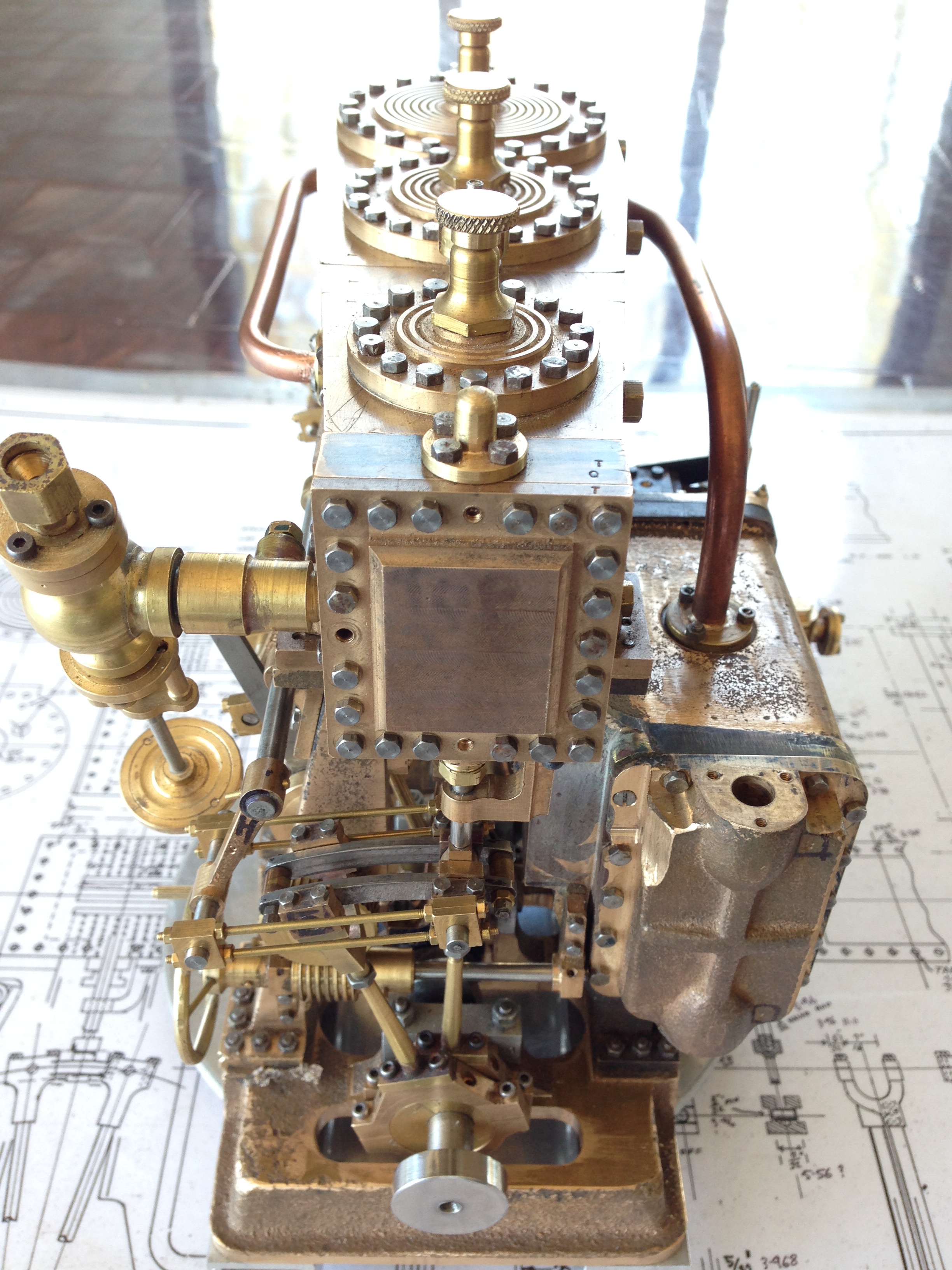
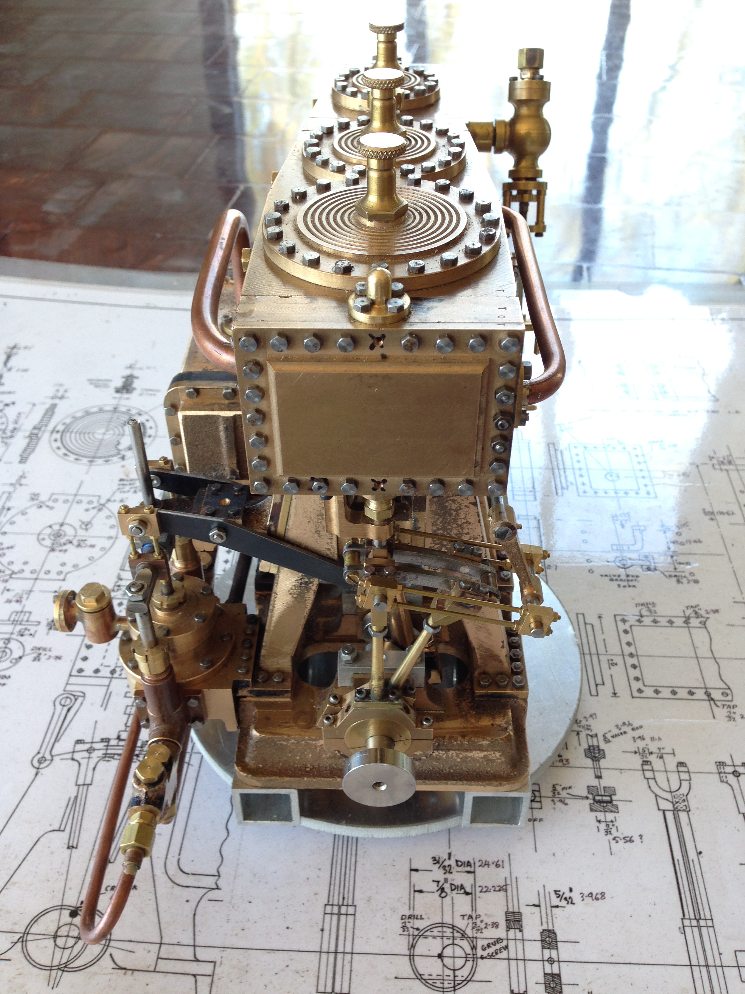
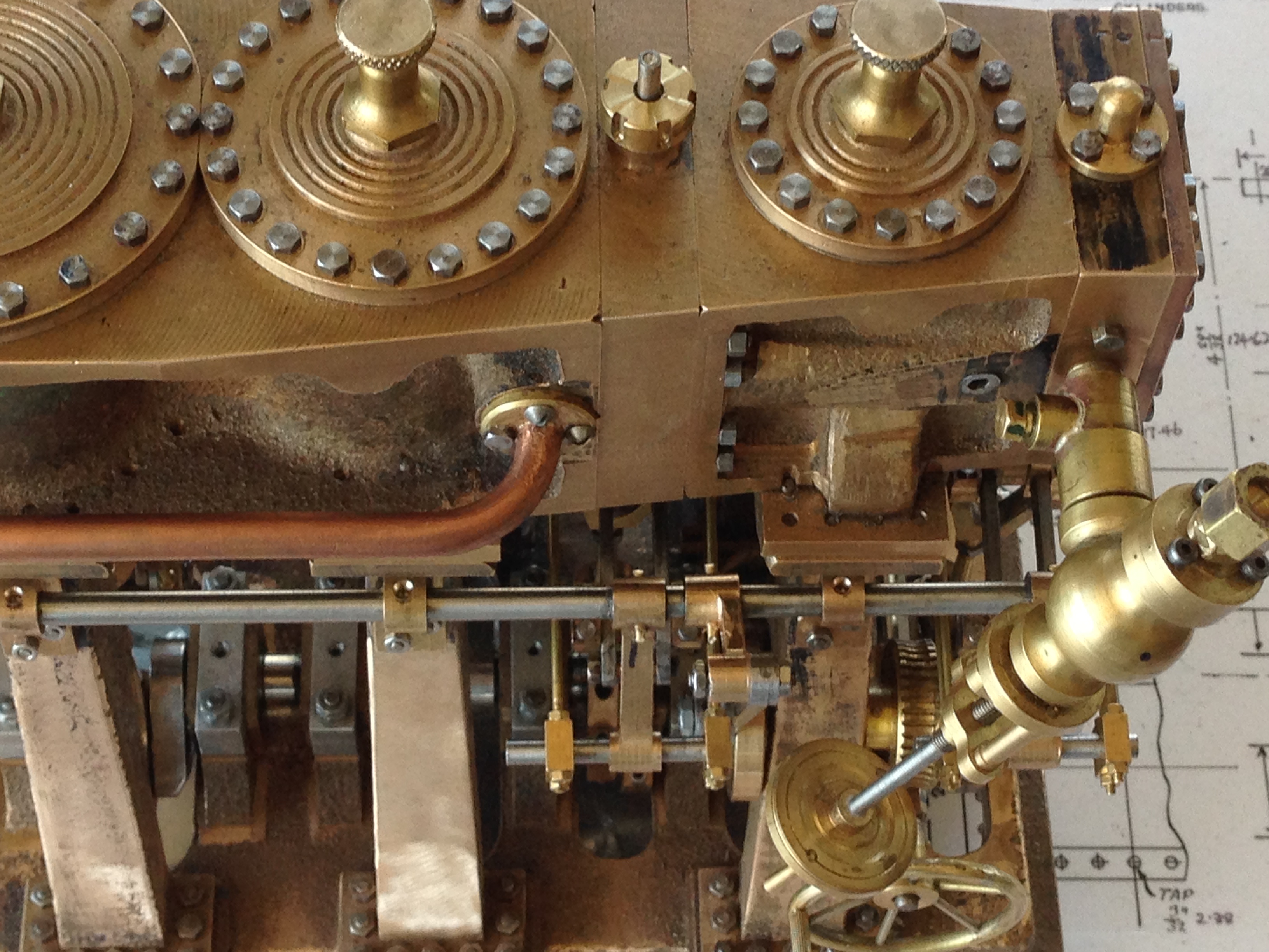
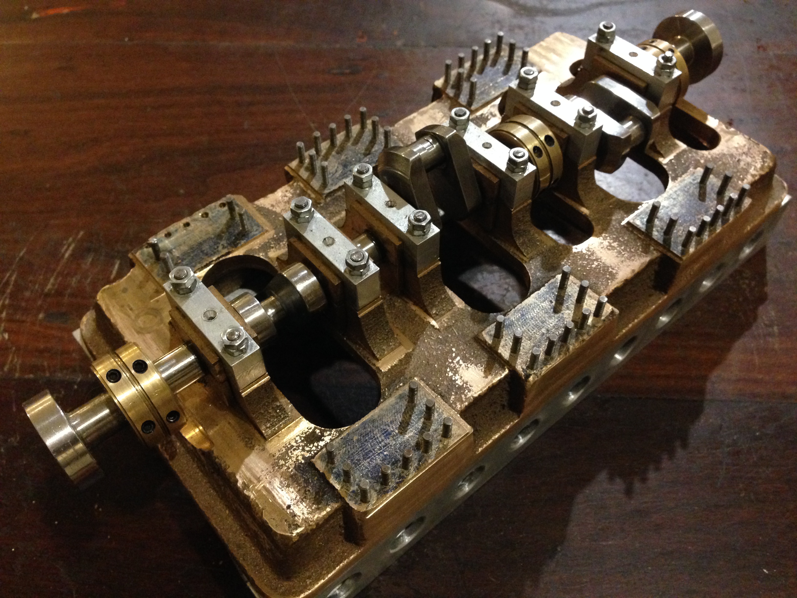
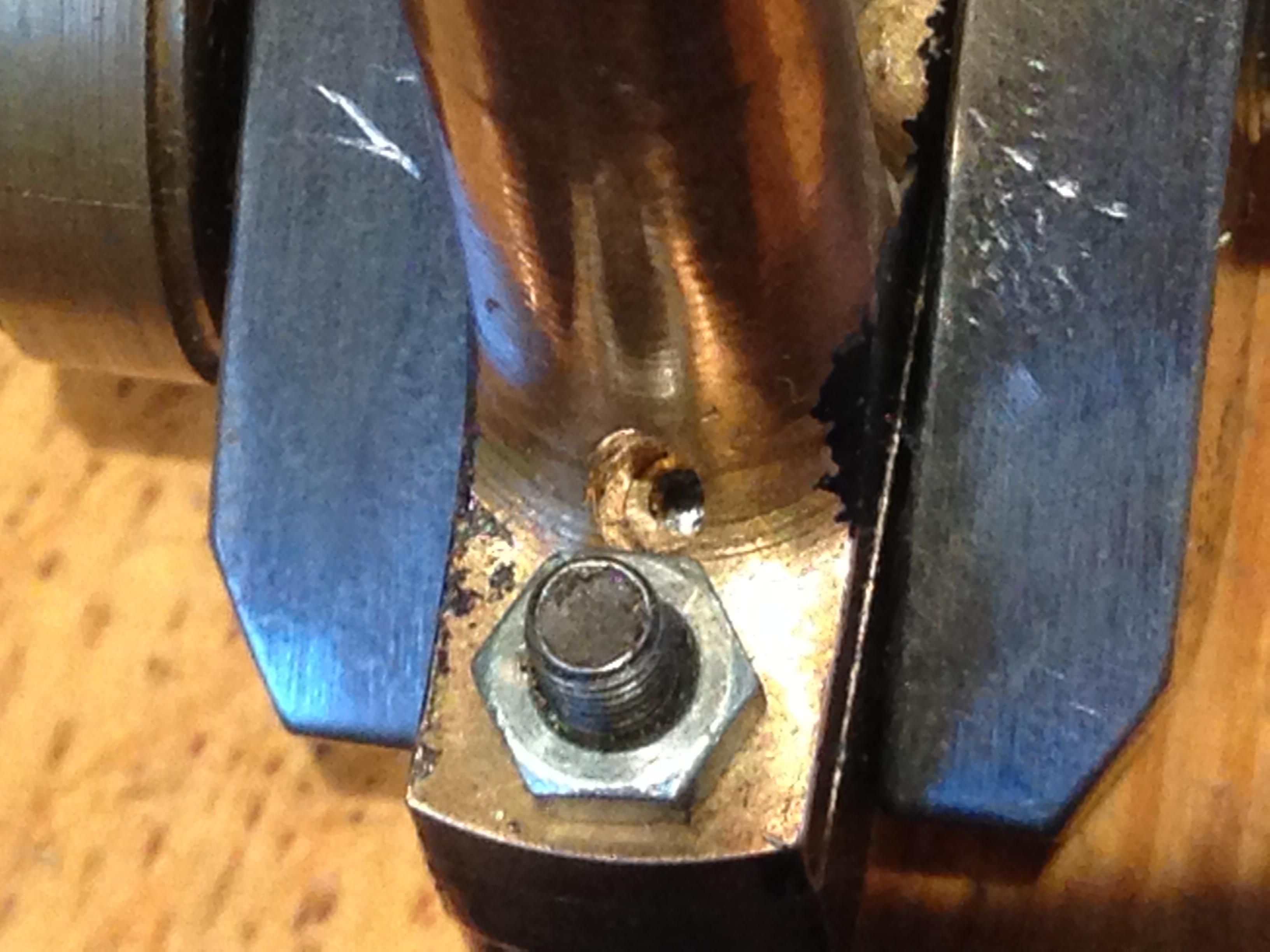
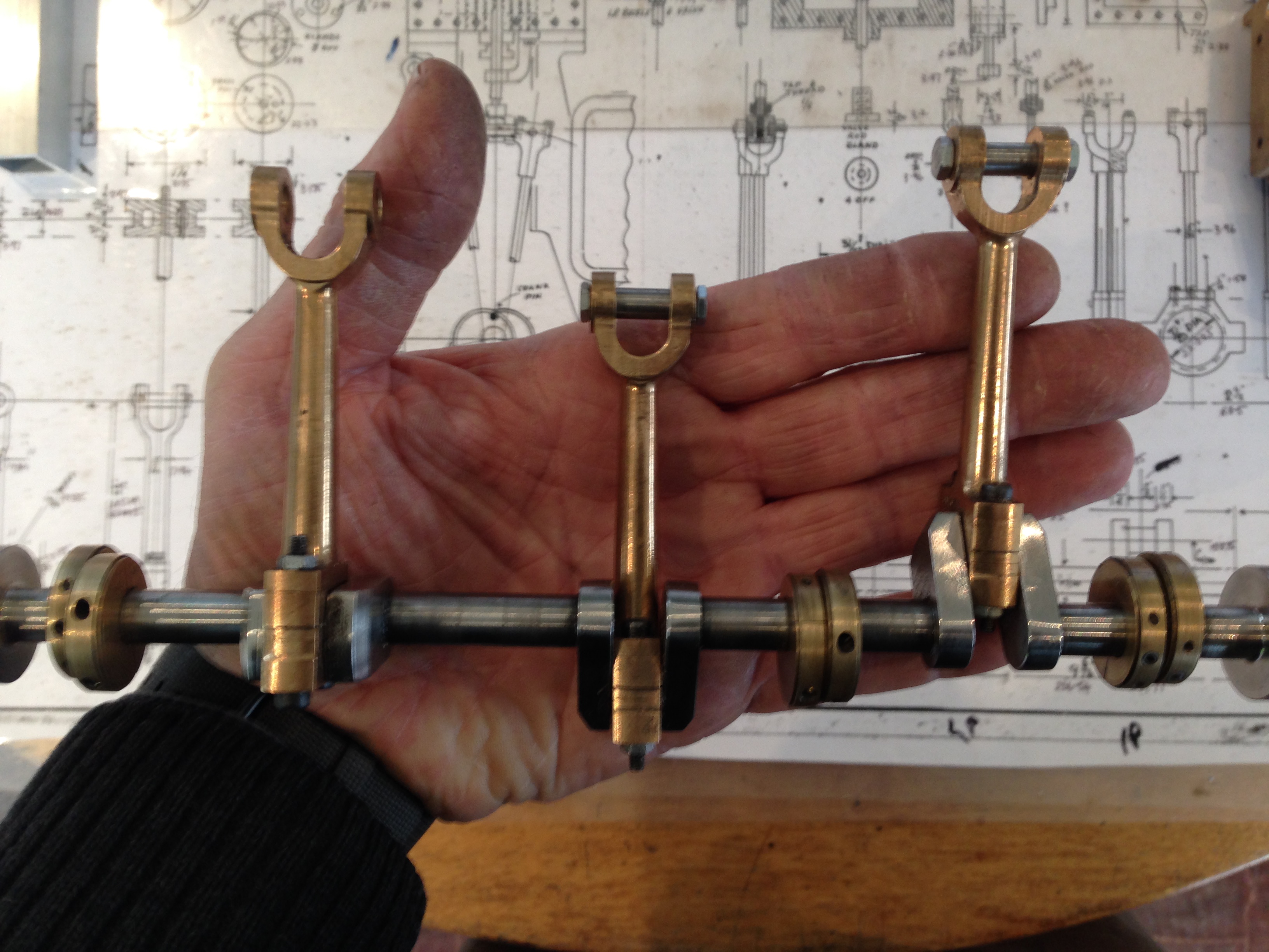
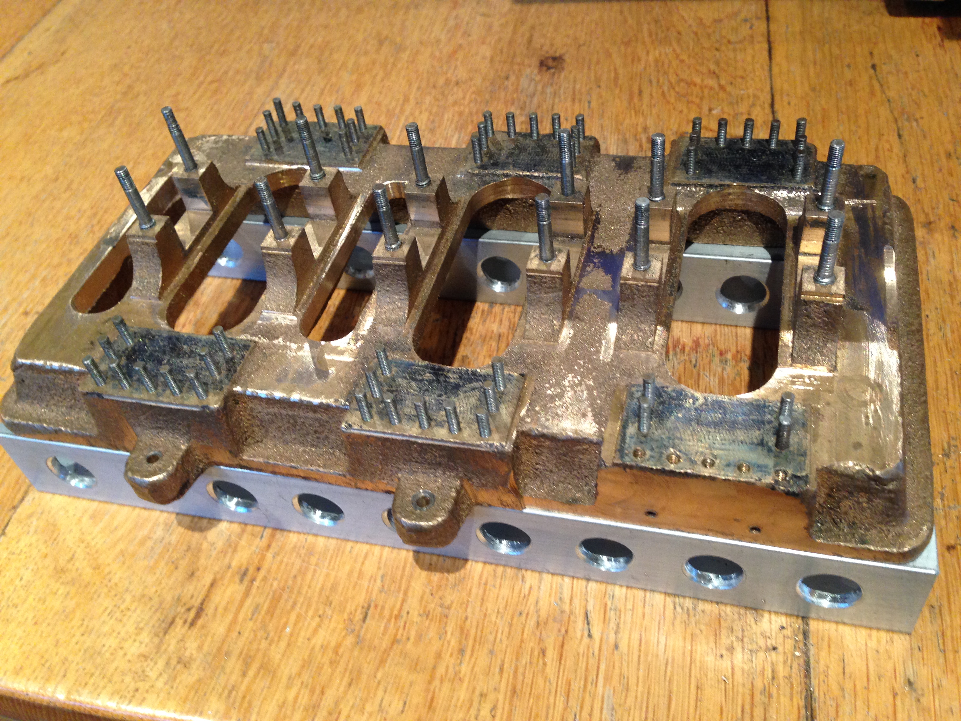
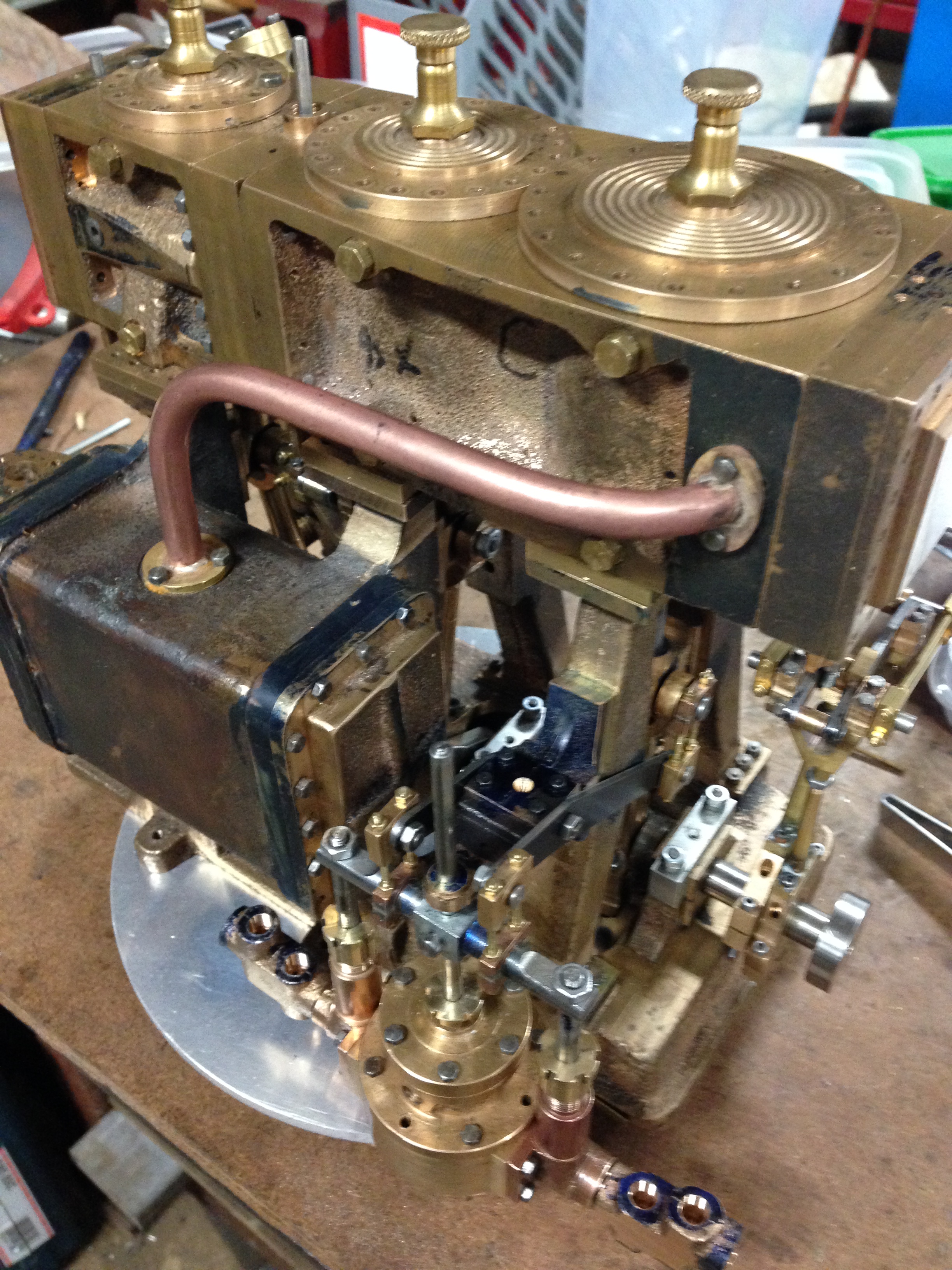
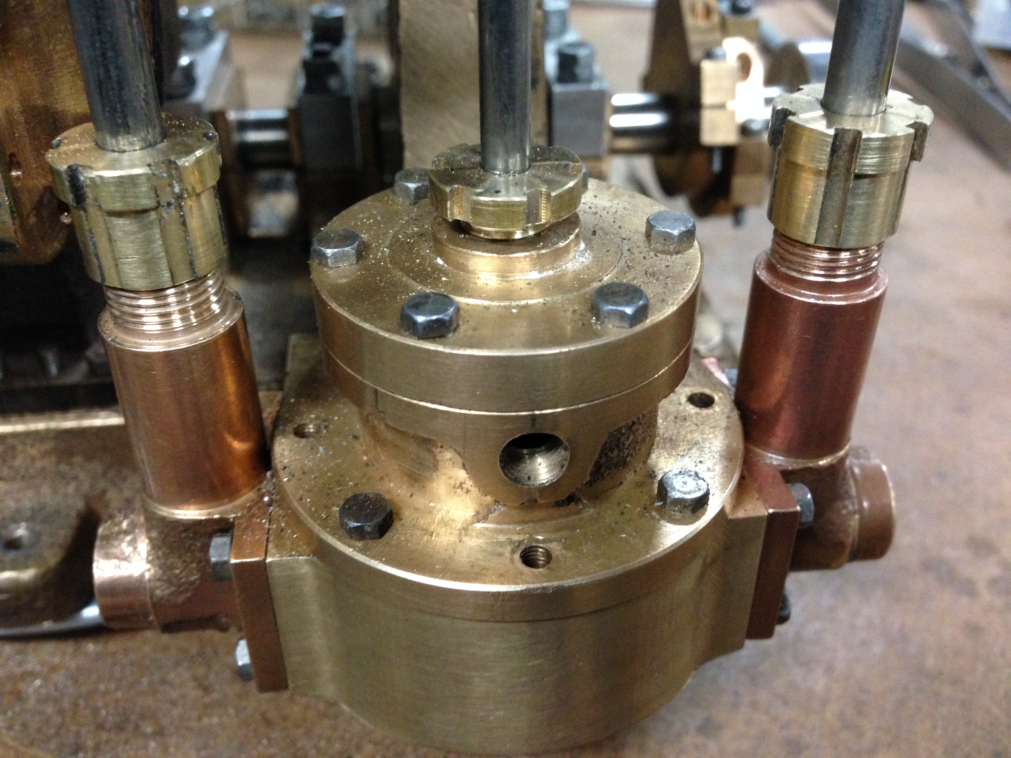
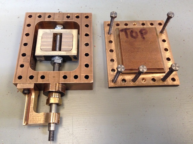
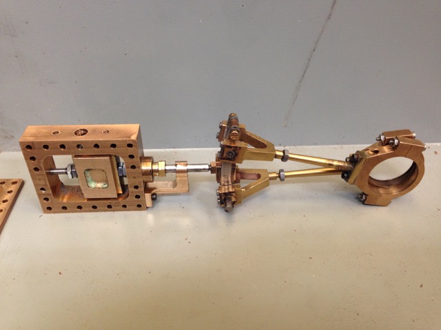
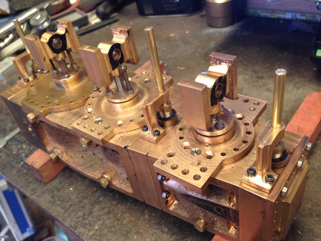
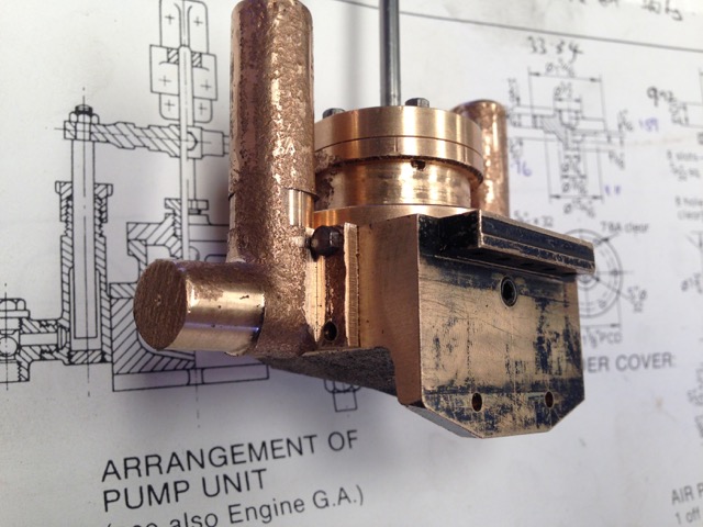
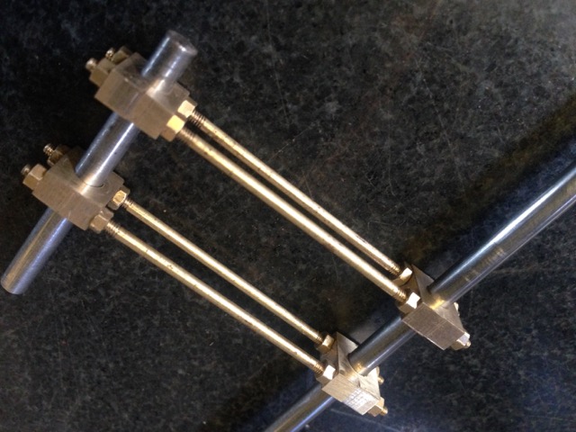
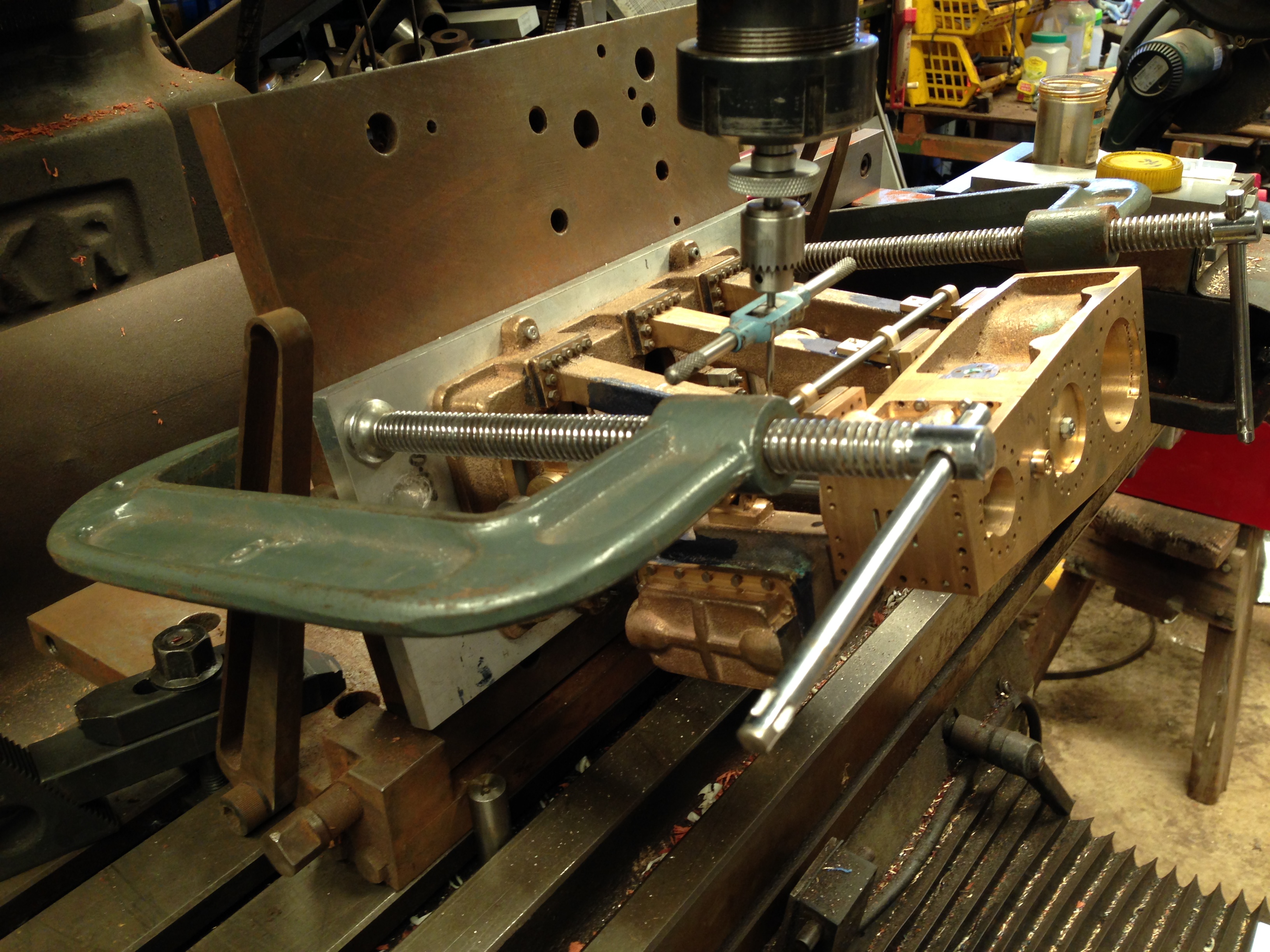
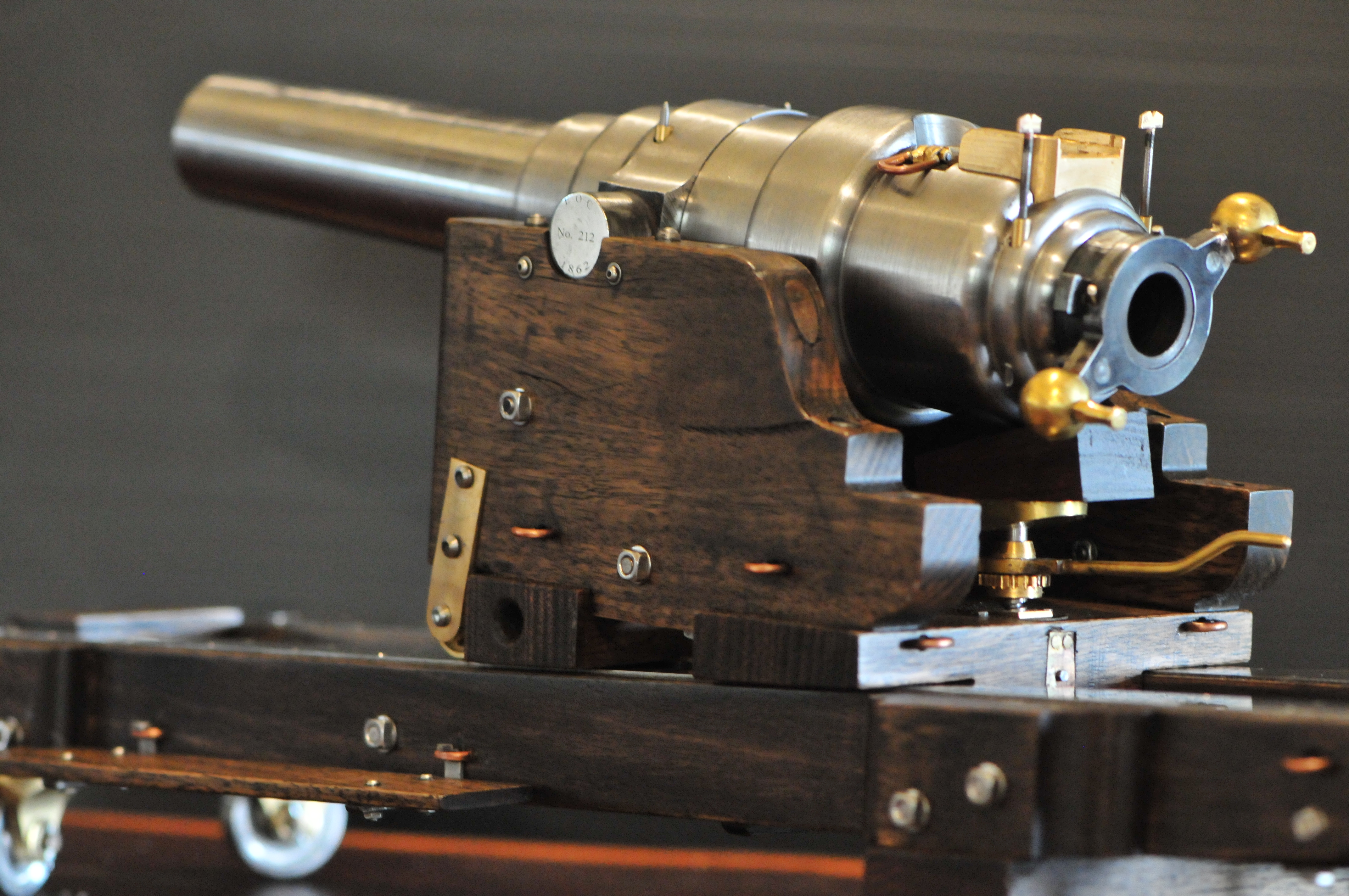
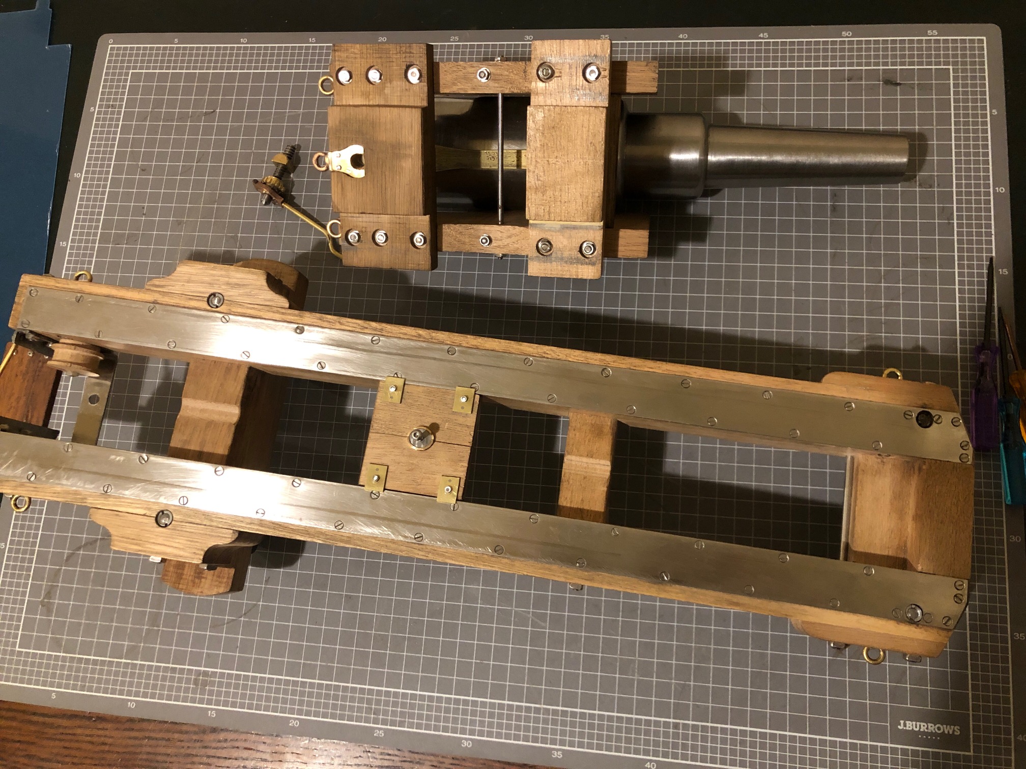
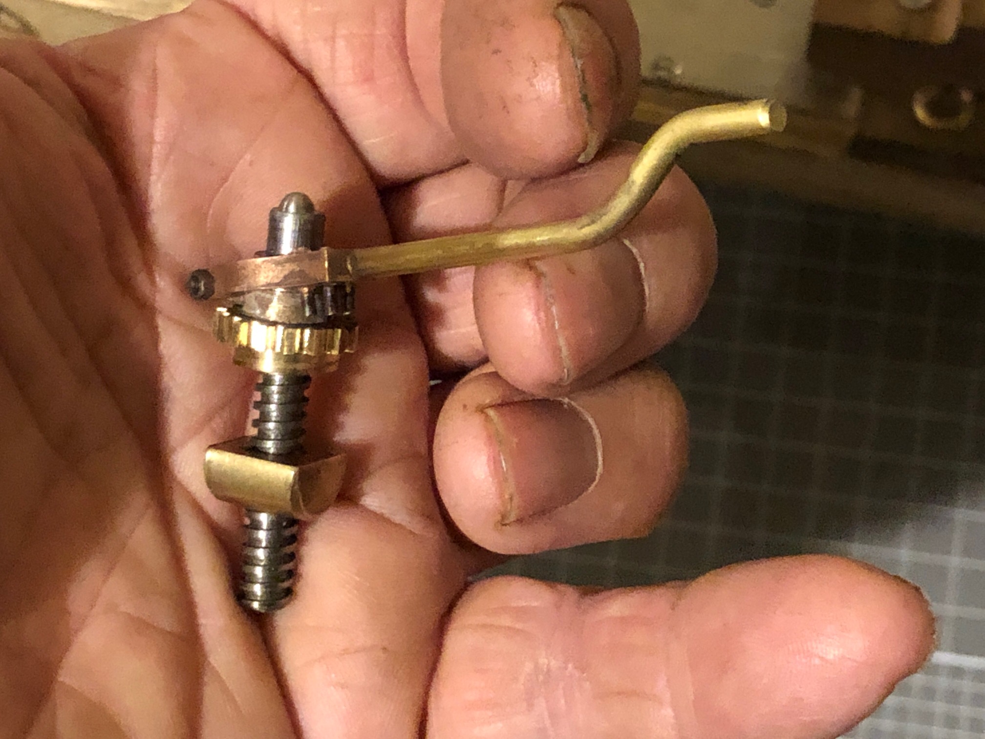
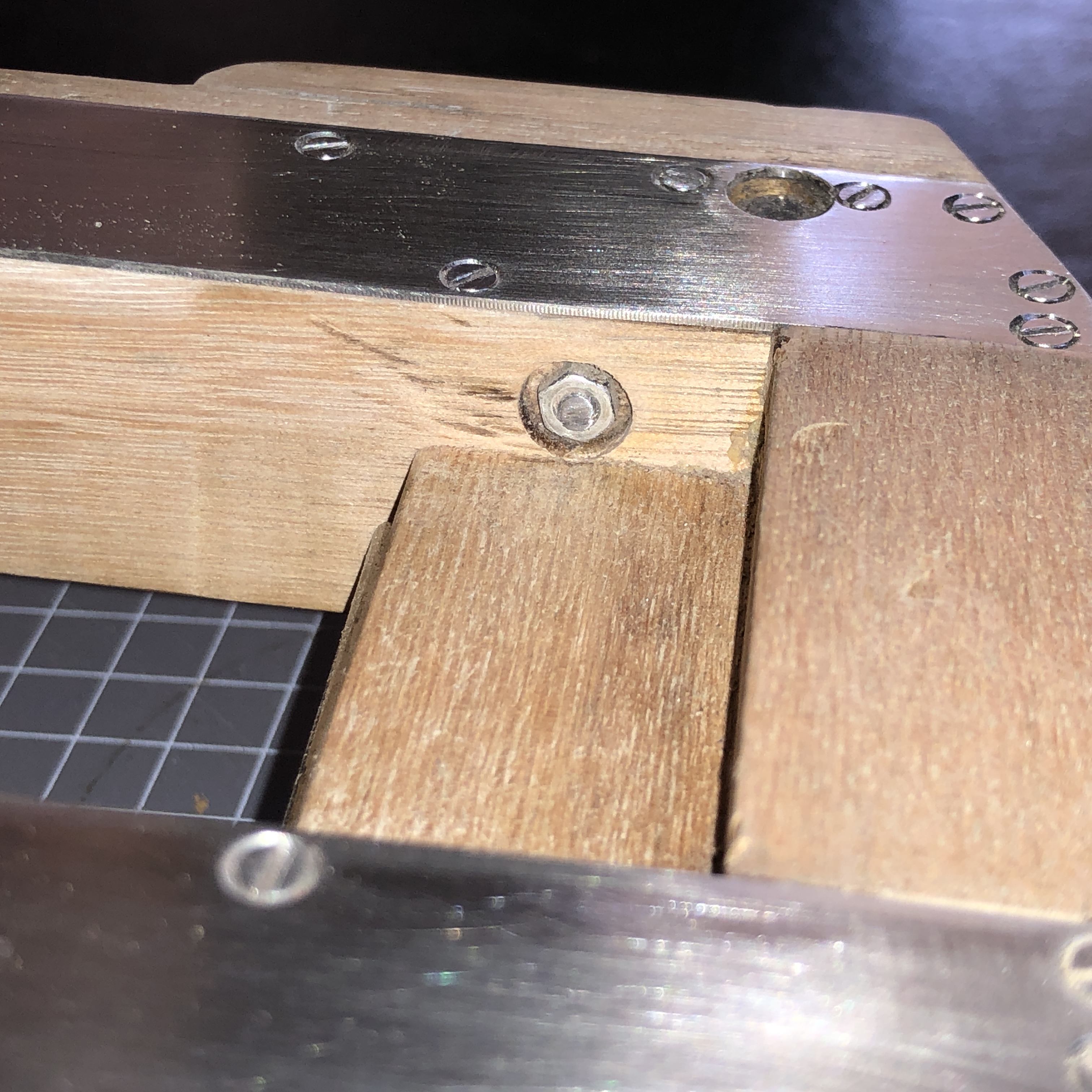
So I spent the day inserting a lot of square nuts on stainless steel studs, and bolting on some valves.   Looks quite interesting?   The stainless nuts came from China and were inexpensive.  A pity to paint them black.

IMG_4001.JPG

The boiler is almost ready for pressure testing.  All of the parts are made, but sealant needs to be applied to the threads and joins, and possibly some gaskets.  I will do a hydrostatic test to 120psi, fix any leaks, then take it to the boiler inspector.  I am aiming to have it certified for 60psi, but will probably run it at maximum 50psi.

I have made the engine cylinder and the bronze cap which seals the vertical tube.  Looking forward to getting stuck into the engine.

Trevithick Dredger Engine. Finishing the flat end plate.

Today I brazed the inspection hatch to the flat end plate.  I did have some qualms about using the shape which I hade made, because it is quite round, whereas the example in The London Science Museum is more elliptical with one edge shaved off, and bolts which are irregularly placed around the perimeter.  But it is done now.  I admit that I was influenced by reactions from club members who were complimentary about the hatch which I had made, picking it out for special mention when I took it to yesterdays meeting.  And if I do not like it later on, I can remove the surface and make another one, more wonky like the original.


IMG_3426 2

The inspection hatch is ready to be brazed into position, and I have made a ring to attach the firebox door and surround.  The blowdown valve is very close and I had to grind a recess.

Before brazing I made a firebox door and surround, and bolted it to the end plate.


IMG_5571

The surround bolts to the end plate, through the ring.  Here setting them up for drilling and tapping the M2 bolts.  That is an adjustable parallel, making sure that the door surround is horizontal.  Being glued to hold the position for drilling and tapping.


IMG_0365

Hand tapping the 2mm bolt holes.  I drilled them after glueing the surround to the end plate with SuperGlue in the previous picture.   Then heated it to release the glue.  Did not break the tap, but I was careful to avoid touching the copper, and used tapping lubricant.


The door is cut out, but yet to make the hinge, catch and latch.


And just to remind you what I initially made, according to the Cain/deWaal plans…


IMG_6652

These parts are now in the “failures” drawer.  Or should it be the “I changed my mind” drawer.


Trevithick Dredger Engine- soldering the big boiler flange.

Today I soldered the large flange which holds the flat end plate, to the boiler shell.  The flange is a large piece of LG2 bronze, but it is quite delicate because the centre is removed, leaving only the rim.

Here is a photo of the flange in position, fluxed, and ready to apply heat and silver.

IMG_2001.JPG

But before this step I made a special tool.  Can you guess its purpose?


IMG_3667.JPG

It is a disk of 12mm thick steel with a steel bar bolted to the surface.   A hint….  the disk diameter is slightly less than the internal diameter of the boiler shell.


IMG_5064.JPG

Here is the tool in use.  With all of the heat from yesterday’s brazing, the boiler shell had distorted slightly, and the flange to be soldered was a bit tight in places.  So I identified the tight spots, placed the tool against the tight spot, and gave the bar a whack with a hammer, slightly expanding the tight spots.   After this, the flange dropped into position easily and nicely.


IMG_2891.JPG

After soldering the flange.  No video I’m afraid.  Not enough hands.   To minimise the risk of the flange distorting with the soldering heat, I rested it on a plate of flat steel during the soldering.   Note the different shape of the forge for this braze.   


IMG_6804.JPG

And after the brazing, the end plate was nice and square.


IMG_0640.JPG

Square in both directions.


Trevithick dredger engine – second silver soldering session.

Soldered the bushes, the boiler supports, and the engine support.  Did not quite have time to tackle the boiler main end flange.


IMG_8988

The LG2 bronze bushes were made yesterday, and the holes were prepared.  Today I fluxed them and silver soldered.  45% silver, cadmium free.


IMG_1299.JPG

After soldering, and before the sulphuric acid soak.  The Hebel blocks are ideal for setting up the forge area to a particular size and shape.


IMG_3236.JPG

The boiler is upside down in this photo.  I have just soldered the engine support.  Looks messy doesn’t it.  But it looks much neater after the acid soak.  And the splodges will vanish after eventual painting.   I used the bolt in the bush to get the support level and straight, while soldering.


IMG_6550.JPG

Then the boiler supports were soldered, and the unit was dipped in 20% sulphuric acid for 15 minutes, after slow cooling.  Note the Plimsoll line, which was the depth of the acid.  I was unsatisfied with the alignment of that boiler support, so I reheated it and tapped it into a better position.  If it leaks steam, I might need to touch it up, but at least it is properly positioned.


IMG_3493.JPG

At the end of this session.  The big flange is just sitting there, waiting for soldering in the next session.


Actually, this was not the first brazing session.  It was the third.  I had previously silver soldered the firetube.  And if you have been watching this build you might recall that I bronze brazed the domed boiler end and the boiler wrapper, and the vertical cylinder into the domed boiler end.  Despite the copper reaching red heat during today’s session of silver soldering, the bronze joins remained intact.  Bronze has a higher melting temperature than silver solder.  Which was one reason I did the bronze brazing first.


Trevithick Dredger Engine Boiler Bushes


IMG_6882

Drilled previously, with wooden plug to prevent boiler deformation


IMG_5178.JPG

Bushes made, but one is a bit tight, so using the Dremel to make it a loose fit, in preparation for silver brazing.


IMG_1993.JPG

That is about right.  Roughly 3-5 thou gap.


IMG_2271.JPG

The middle bush and the right hand one are additions to the Trevithick concept.  The middle one is a banjo fitting which will eventually connect to a modern pressure gauge… a boiler inspector requirement.   The big one is a water filler point.


IMG_8988.JPG

All plugged up, ready for silver brazing then a boiler inspector hydrostatic test.  The thread which is visible is blind.  It does not communicate with the boiler cavity.

Ready for silver brazing in a day or two.


Trevithick Dredger Engine Progress

Made the cylinder, boiler bushes, and engine supports today.


IMG_9874.JPG

The cylinder is LG2 bronze.  Drilled and reamed the 20mm bore, turned the outside diameter between centres, then milled the rectangular steam inlets at the ends.  The inlets were actually milled then the square corners were filed.

The boiler bushes are also LG2 bronze.  Straightforward turning.  Not quite finished.


IMG_2269.JPG

The cylinder support looks simple but it is more complex than it looks.  The middle is LG2 bronze, but I did not have a large enough piece of bronze, so the wings are brass.  The join is bronze brazed, so it will not come apart when it is silver brazed to the boiler.  The angled supports are a tight press fit into the wings.


IMG_6925.jpg

Next I will silver solder all of the joins.  They are just sitting in place in this photo.


Trevithick Dredger Engine – what was the original design? -2

Further reading and exploring web sites, email to London Science Museum (LSM), asking opinions of boiler experts.  Even considering a quick trip to London. (from Oz).

What I have learned is interesting.

Richard Trevithick did not manufacture any of the several hundred of his high-pressure engines.  The ideas and designs were his, but the engines were manufactured in different sites and by different makers.  The designs changed with time and as new ideas presented themselves to the brilliant mind of Trevithick.  And each manufacturer put their own stamp on the designs.

For example, look at the following pictures of the boiler flat end plate.  One is in two pieces, riveted together.  The other is a casting, and the flanges for the inspection hatch and the chimney, and probably the blowdown valve orifice, are almost certainly part of the end plate casting.  The firebox looks newish, slipped inside the original end plate casting.  I guess that the original firebox had burnt out, but was probably similarly held in place.   If any Brit readers can pop into the LSM and check this out I would be very grateful.

Trevithick boiler shell

B002617 hi res

The model which I am making, and dithering over the end plate design, is based on the reconstructed engine in the London Science Museum.  I intend to remove the aspects which are obviously Victorian in origin, and replace those with parts that I think will be closer to the Trevithick era designs.

Unfortunately, I have already made some of those parts, so my redesign is a bit compromised, unless I scrap them.  Which I do not intend to do.

So this is my redesign of the end plate.  Not quite LSM.  And not quite Tubal Cain/deWaal Not quite, but will have to be close enough.  The red lines are already machined so I am stuck with them.  14 drilled and tapped holes have been filled.  The bronze inspection hatch/plug has been made, but with less standout than shown in the lateral view.

end plate

As an aside, while pondering the end plate, I have made a start on the engine itself.  The cylinder has been roughed out, and will be finished in my next workshop session.  Cain specified brass, deWaal specified bronze.  So I have compromised, and have used an unknown brass/bronze/copperish lump of workshop metal.  It is certainly hard, as assessed by filing.  Photo next post.

New Spindle Motor for the Boxford 125TCL CNC lathe.

Reader Ben asked about the spindle motor replacement on the Boxford.   This is a small CNC lathe, and was often used for teaching in secondary schools in Australia.  Mine was made in 1985, and I replaced the electronics a few years back because they were obsolete and not functioning.  The mechanicals of the lathe were beautifully made and in excellent condition.  I did replace the ball screws, but in retrospect, that was probably unnecessary.   I also installed new and bigger axis stepper motors.

I was still getting some unreliable results, despite the the upgrades, and wondered whether the spindle motor was lacking power.  I was taking lighter cuts to try and cope but clearly a new spindle motor was required.

The space that the motor occupies is fairly tight, and initial searches for a suitable replacement were fruitless.  The new  ClearPath motors looked promising, but enquiries to the manufacturer indicated that the required power and rpm’s were not available.  Then my expert friend (or should that be “friend who is an expert”?), spotted the Ebay ad below, and bought and succesfully installed the servo motor in his 125TCL, so I did likewise.  I am afraid that the electronic aspects remain a mystery to me, so I cannot help with those.  It is a 0.75kW motor, substantially more powerful than the original, but very compact.


Servo Motor.jpeg

Do an Ebay search on the code on the controller.  I paid $AUD339 but it is now plus postage and GST, so close to $AUD400


IMG_6912

The new spindle motor and servo controller


IMG_6910.JPG

A new motor pulley was required.  There is still a high and low belt ratio available, but with the extra power and torque I never use the low ratio.  RPM range is 300-3200.

IMG_6913.JPG

This has been a very successful modification.

Many thanks to Stuart Tankard for his generosity in time, expertise and advice in getting it going.


Trevithick Dredger Engine. What was the original design?

As I am progressing with building the 1:8 model of the dredger engine, I am experiencing doubts about the authenticity of the design by Tubal Cain 1985, and redrawn by Julius DeWaal 2016.  Those plans are based on the engine in the London Science Museum, which we know was incomplete when found in a scrap yard (?) and reconstructed in 1886.  There are no known or published original plans.

Look at the following photographs.  The first two are boiler components labelled as Trevithick, although incomplete, appear to be unmodified.

The following drawing comes from Rees’s Cyclopaedia, published first in 1819, when many of the engines would have been operating, and given the quality of the drawing, is likely to be fairly accurate.

Finally, the engine in the London Science Museum, which shows some Victorian era features which are highly unlikely to be as Trevithick designed them.


Trevithic boiler tubes

The firebox and firetube, riveted to the end plate.  Note the inspection hatch has no rivet or bolt holes.  How would the hatch have been attached?  


Trevithick boiler shell.jpg

Showing the end plate bolted to the cast iron boiler shell.  Interestingly, the penetrations are mirror image of the LSM engine.  Does anyone know where this boiler is currently located?  And why are there no rivet or bolt holes around the inspection opening?


trev_1

Drawing from circa 1819.  Note 1. the wooden support at the chimney end of the boiler, 2. the flange for the chimney attaches directly to the end plate, as does the inspection hatch and the firebox door.  None of these protrude beyond the end plate.


B002617 hi res

This is the best photograph I know of from the reconstructed LSM engine.  There are multiple inconsistencies with the Rees drawings…

The inconsistencies which I note are:

  1. The support under the flat end is metal, not wood.  It is cast or fabricated, and curved.  Unlikely to be original.
  2. The rear support in the Rees drawing is metal which sits on wooden bearers.  Quite different shape from the Cain/deWaal plans.
  3. Some of the flywheel spokes have a moulding, some are plain.  I imagine that plain is more likely original.
  4. The connecting rods are bent at the top.  They are straight in the Rees drawing.
  5. There are no rivets or rivet holes around the firebox.  There appears to be a new cylindrical insert into the firebox. Unfortunately the Rees drawings do not show the firebox.   The firedoor hinges appear to be welded in position.  There are holes in the firedoor which could have been used for strap hinges, which would be more likely in use originally.  There is no provision for air intake control.  I wonder if Trevithick would have provided an adjustable flap?  I am told that some early Cornish boilers did not have any flap.
  6. The inspection hatch looks realistic.  But the hatch sits away from the end plate, presumably to permit access for the end plate to flange bolts.  Would Trevithick, I wonder, have designed such a complex setup?  Bearing in mind that every piece of iron or steel must be shaped in a forge by a blacksmith, then riveted or bolted into position, or cast iron, then bolted into position.   The rather irregular position and shape of the inspection plate and bolts looks authentic, but I have my doubts about whether the inspection hole itself is authentic.  Could this have been cut out later, when boiler repairs were required?

I have not looked closely at the engine details.  No doubt further inconsistencies will be apparent there.

So I am in a bit of a quandry.  Do I make the Cain/deWaal model, removing the obvious inconsistent features but including the dubious ones?  Or do I guess at what Trevithick would have designed, based on the technology which he had available?

Any opinions or thoughts/advice would be welcome.


Drilling holes into the Trevithick Boiler

Nothing much to add today.  I had only an hour in the workshop.  But here is a photo.


IMG_6882.JPG

The wooden plug is to prevent squashing the boiler shell in the vise.  Note my ambidexterity regarding metric and imperial dimensions.  

And as a matter of interest, a stranger turned up at our working bee in the exhibition cage, with 2 models about which he wanted some advice.   The models are beautifully made, and we hope that the stranger will join our little club.


IMG_6895.JPG

A Stuart Turner 5A with Stephenson’s link reversing mechanism.


IMG_6888.JPG

And I could hardly believe my eyes when I saw his 5″ boiler.  It is made to the plans upon which I based my 6″ boiler!

He inherited the models from a relative.  Lucky!


Trevithick Dredger Engine- First silver soldering session

Today I fitted the chimney right angle piece, drilled and soldered on its flange, and drilled the end plate to accept the flange.  Then I CNC drilled the big bronze end plate to accept the flange.


IMG_6880.JPG

The angle piece is a commercially available plumbing part.  The stainless steel square nuts came from China.  Joins are silver soldered.  In a departure from the Tubal Cain/Julius deWaal plans, I decided to attach the chimney flange directly to the flat end plate.  I reckon that’s what would have been done in 1806, and it is what shows in the 1820 Rees Encyclopaedia drawing.   Note the unwanted threaded holes, now filled with stainless steel threaded rod.

Then I carefully positioned the bronze end plate, the firebox and the firetube, and silver soldered them together.


IMG_6877.JPG

The parts are fluxed and pushed together, ready to apply some serious heat and expensive silver.


IMG_6878.JPG

Not pretty, but I am happy with the silver joins.  Minimal retouching required.

Next, the inspection hatch will be soldered to fill the rectangular hole.

Then the main bronze flange will be permanently attached to the boiler shell.  I intend to silver solder it, but considering bronze brazing.


Back to the Trevithick Dredger Engine

The 6″ vertical boiler is virtually completed.  Well, actually, I still have to make a Duplex steam pump, fit a steam injector, make a steam delivery manifold, paint some bits….  but yeah, emotionally, for me it is finished.   I will get back to those bits as the mood takes me.

So I have picked up the bits of the Trevithick steam dredger engine.  I will concentrate on the boiler, so I can get the AMBSC certification, then take a leisurely approach to the engine.  You know, 2 weeks to the boiler certification then another 4 weeks to finish the engine.  Or something like that.


IMG_6869.JPG

As you can see, I have redesigned the inspection hatch, and made the new version.  This is still not quite authentic, but it is much closer to the London Science Museum example.  The inspection hatch will be permanently closed, silver soldered shut.   And the wording reflects the fact that this is a model.  The model hatch is circular, whereas the LSE example is something between a circle and an ellipse.   Trouble is that we do not know what is original Trevithick and what was altered in 1870.   So I do not feel too guilty that I am guessing.


IMG_6868.JPG

Sorry about the poor focus.  I will retake this shot later.  You can read my new AMBSC ID number.  I do feel presumptuous writing my name the same size as Trevithick.


IMG_6867.JPG

I have marked the boiler perforations and will drill the holes then make the bronze bushes.


B002617 hi res

A hi res photo of the dredger engine in the LSM.  You can see that the inspection hatch is something between a circle and an ellipse, not a rectangle. And that firedoor hinge is definitely sus.


6″ Boiler Lagging -3, and back to the Dredger Engine.

The brass bands which secure the wooden lagging strips were installed.  5 bands were required to make sure that every piece of wood is held once the glue lets go.  The bands are only 4.75mm wide.   The bolts which apply the tension pass through small brass blocks which are silver soldered onto the ends of the strips.  (thanks Ben De Gabriel of EJ Winter for that tip!  And for the band material!)


IMG_6860.JPG

The boiler sitting on our kitchen table.  I will eventually paint the ashpit door assembly and angle plate at the base.


IMG_6859.JPG


IMG_6857.JPG

The setup for holding the small blocks in position during silver soldering.  In order to not close up the gap between the small block and the brass strap, I centre punched the blocks, raising small dimples, which produced a thou or two of separation between the parts, allowing the molten silver solder to flow.  That silver solder wire is 0.5mm diameter. 


And back to the Trevithick Dredger Engine….


IMG_6855.JPG

The redesigned inspection hatch.  The bronze rectangular bit plugs the hole in the end plate.   I have plugged the unwanted 14 holes in the end plate, using stainless steel threaded rod.   And metal worker’s hands, cut, dirty, dry thick skin (SWMBO “don’t come near me!”).


FullSizeRender 10.jpg

Four of the plugged holes around the firebox opening, 10 more under the inspection hatch (hidden), and the inspection hatch.  I will make the inspection hatch a little bit smaller.  It will be decorative, permanently attached and unable to be opened.  The dredger engine in the London Science Museum has the manufacturer’s name cast into the plate.  I am contemplating just inserting Richard Trevithick’s name and the date the first high pressure engine was made (1806).  There will need to be a separate area on the boiler wrapper the AMBSC identification.


Boiler Lagging -2

The Tasmanian Oak lagging looked too pale white to my eyes.  With use, steam, oil, dust, water, workshop grime and sunlight, it would have gradually acquired a well-used patina, but I prefer instant gratification.

IMG_6842

So after consulting my resident wood finish, artist, architect, expert, (SWMBO), I applied some wood-stain.


IMG_6846.JPG

Too orange, too patchy, she said.   And the white in the joins looked wrong.

Too orange, too patchy, and too much white showing.  “Put on some black boot polish” she directed.

So I did as I was told.


IMG_6848.JPG

With a boot polish brush…


IMG_6851.JPG

—and a toothbrush…


IMG_6852.JPG

… hmmmm.   I better clean her toothbrush before putting it back….

…(acknowledgments to Tubal Cain for using his old gag…)


IMG_6853.JPG

That’s the look I was wanting.

Now just waiting for the brass bands to arrive.

Ben De Gabriel from EJ Winter, Sydney, had sent me a remnant piece of banding to try, in my last consignment of parts from him.  It was perfect, but not enough for the 5 bands which I require.  So I rang him.  He thought that was the last of his stock of that particular size but he would check and let me know.  Sure enough, he returned the call, and he had found a couple more bits, and they would be just enough.  Old stock, a bit shop-soiled he said.  So I could have it for nothing!

Readers who have been with me for some time will know that I have bought 3 sets of engine castings and plans from EJ Winter.  The Bolton 7 horizontal Mill engine, the Bolton 12 Beam engine, and the Bolton 9 triple expansion engine.  A bit of very interesting news is that Ben is planning a new set of castings for the triple, using the lost wax casting technique, which gives a finish which should require machining on the mating surfaces only.  That sounds so good that I am almost tempted to make another triple.   Almost.   Some months until availability though.  (Hope that you don’t mind my premature announcement Ben.)


6″ Boiler. Lagging.

Lagging.  As in boiler insulation, not as in failing to keep up.  I have been working on the boiler for about 3 months, so I am actually happy with the progress.  And more than happy to have passed certification!

I decided to apply wooden lagging strips for the appearance and for ease of handling, rather than any minimal improvement in performance of the boiler.

After use, the boiler shell is too uncomfortably hot to handle, so there is a waiting time of 30 minutes or so to allow it to cool.  I am hoping that wooden lagging will reduce the waiting.

And wooden lagging will hide the splodges of silver solder around each boss and join.  And it looks the part IMO.

But how to attach it?  None of my books mentioned any method.  I presumed that the brass strips are the main method, and that is certainly so, on full-size boilers.   Then I found a short video on YouTube by Keith Appleton and I decided to copy his method.

The method uses Super Glue as a temporary securing method while positioning the strips, then applying brass strips to hold the wooden strips in place long term.  The boiler heat and expansion-contraction will result in the glue bond being temporary, and if the wood strips have to be removed later, for any reason, that will be possible. It also means that an insulating blanket cannot be inserted between the copper shell and the wooden strips, but I was not planning on using a blanket, so not a problem.


IMG_6821.JPG

The strips are 3x8x265mm.  I chose Tasmanian Oak which is actually an ash, because it is hard, fine grained, and I had some in old floor boards.  I cut the pieces to length a bit oversize, then ripped them to size on the bandsaw.  It is difficult to avoid fingers being close to the blade with small pieces like this, so I used a push stick.  I needed 65 pieces.  The blade teeth are a bit too coarse for this job, but I was too lazy to change it for a finer one.  Note the saw blade guide.  I did not like the one which was provided by Metabo, so I made that one.  Works well!


IMG_6822.JPG

Then I used a belt sander to remove most of the sawing marks.  The resulting thicknesses varied from 2.8 to 3.4mm but I hope that variation will not matter.


IMG_6824.JPG

Some hand sanding to remove wood fur.


IMG_6829.JPG

Hope that this will be enough pieces!


IMG_6830.JPG

The boiler feels out of place in all this woodworking rubbish.


FullSizeRender 18.jpg

SWMBO was away, so I set up on the kitchen table.  Here deciding on the final length of the strips.


IMG_6835.JPG

Each piece is cut to length, then fitted into position.  Shaping the wood to fit around bosses and fittings is done with a small sanding drum in the Dremel.  It is a slow process.  Then each piece is glued into place, and held with rubber bands.


IMG_6836.JPG

It has taken about 4 hours to apply about 1/3 of the strips.  The Baileys was to keep me in an appropriate mindset.  I am looking at the slightly ragged top and bottom edge in the photo.  Looks a bit rustic and authentic, or just rough?   The wood will be darkened after oiling, and possibly staining.  And Tasmanian Oak darkens with exposure to light.

That was yesterday.  Today I hope to complete this job, but SWMBO is home, and not appreciating the dust and mess, so I am exiled to the outside.

I have realised that to secure all of the wooden pieces I will require 5 brass bands.  I do not want it to look too brassy, so I am ordering narrower strips than the 6mm material which I had previously bought.  I think that 4.75mm will be about right.


VR-18-18

VR-18-18 Stands for Victoria, Geelong Society of Model and Experimental Engineers, 2018, 18th registered boiler for the club.

So this morning I fired up the boiler with the boiler inspector closely watching.  The gas was turned to maximum, and the water was showing full.

Steam appeared about 10 minutes later and the Sandberg safety valve started popping at 100 psi. Every couple of minutes the safety valve released and the pressure remained in the 97-100 psi range.  This went on for about 20-30 minutes.  All to the satisfaction of the inspector.

He was happy with the standard of the build, the pressure test, the accumulation test, and that all requirements had been met.

The boiler is now certified for 4 years.  There has been a change in protocol about which I was unaware.  The previous certification rule was for 12 months only, and retesting was required for a further 3 years.  So this new rule is much less time consuming for me and the inspector.  He is happy that before the next testing I will have a steam pump and a steam injector installed.

IMG_6817.JPG

I was so delighted with the result that I treated myself to a trip to the non ferrous metal supplier, and bought a selection of hex brass stock for the workshop.  When I returned to the workshop there were still a few hours of daylight, so I spent the time making the new inspection hatch for the Trevithick dredger engine.  Not quite finished, so no pics yet.

The next step for the boiler is to make and attach the wood lagging and to put on some paint.

New Skills in Retirement.

When I retired from my profession almost 4 years ago, I had an aim to become proficient at in CNC machining, and 3D CAD drawing.

I have definitely improved in those areas.  Trouble is, that as usual, the more that you learn, the more you realise that you need to know.

And in making some items, you encounter the need to learn skills entirely unexpected, like bronze brazing.

And all the while, your eyesight is deteriorating, your memory has gone somewhere (I forget where), and by mid-afternoon, all you are thinking of is sitting down with a good red.

One unexpected skill which has surfaced, which I am really enjoying, is cooking.

My wife, who is still working at what she loves,  announced a couple of years ago that since she is now the bread winner, that I could take over the cooking.  That was OK.  In fact it was something which I wanted to do when I was a teenager, but my rather traditional Mum did not think was appropriate.  So except for doing the camping cooking and barbeques, I did not cook until in my late 60’s.

Then I started cooking the evening meals.  And really enjoying it!  And my wife loves the freedom from the chore.

Trouble is that I detest shopping.  So the solution was a box of recipes and ingredients delivered once weekly.  HelloFresh.  It has been superb.

Then recently the cardboard box was not delivered.  Or at least it was not there at 7am on my doorstep, having been delivered at 2am.  A date stamped photograph was proof of delivery.  So it had been delivered, and stolen.  I am suspicious by nature, and having had no thefts here in 40+ years, I wondered about the delivery person.

Hellofresh took no responsibility.  I had no evidence to support my suspicion.  So we ate toast and cereal and take away for a week.  But I was really pissed off.

So I have spent several days installing a surveillance camera system.  I had installed a similar system some years ago in my workshop, so I felt reasonably confident that I could manage it.  Buying the system was straightforward.  Seems that they are commonplace.  4 cameras.  Recording machine with 2 terabytes of hard disk!  And connected to the Internet, so I can see what the cameras are seeing at any time, on my iphone!  And get alerts if the motion plus heat detectors are triggered.  Amazing!

Trouble is that I had to install the system myself.  It seems that the legal system has pushed professional installers to extinction, by making them legally responsible for thefts where systems are in place.

And at 68, I did not enjoy getting up and down ladders installing cameras and cables.  Or scrambling about amongst the spiders and crap under the house.  But at the time of writing the system is in place.  And working.    Another retirement skill.

And the clarity of the 4K pictures is outstanding.

What I will do if the alarm is triggered is another question to be pondered.  This is Oz, not US, so going outside with guns blazing is not an option.  Thank goodness.

A steam driven water pump, and a whistle.

Boilers, whether full size or model, get through substantial volumes of water.  When my 6″ vertical boiler is working hard, so is the water pump, to replenish the water which is turned to steam.

At present, the water pump is a manual pump, and it needs to be operated almost continually when the boiler is steaming hard.

IMG_6791

I am not sure whether operating the hand pump (lower right), or the propane burner, consumes more energy.

So it was with great interest that I viewed the steam pump in operation which was built by Stuart Tankard, at last night’s meeting of GSMEE.  I have plans and castings for the same unit, and expect to make it later this year.  It is a Worthington type pump, and the castings and plans were supplied by Southworth Engines.

IMG_6664

Stuart’s latest.


In this video, for the demonstration, the pump is running on very low pressure compressed air.  The larger cylinders are the steam powered driving cylinders, and the smaller ones are the water pumps.  So whatever the pressure of the steam, the water pressure will be greater, and able to be pumped into the boiler.

And finally, I bought a steam whistle.  It was supplied by Microcosm.engine from China and it was very reasonably priced. ($US39).  I have not tested it yet, but it came highly recommended by Keith Appleton.  It is certainly very nicely made.  I screwed it onto the boiler as a bit of bling because I showed my boiler progress at last night’s meeting of GSMEE.

IMG_6790.JPG

Almost ready for the boiler inspector.

Almost ready for the boiler inspector!

It feels like the countdown to the finals medical exams!

So today, I drilled the gas jet from 0.22mm to 0.3mm.   A drill bit to drill 0.3mm, is, at least to my eyes, barely visible.  It is finer than the finest sewing needle.  If I pick up a 0.3mm drill bit I can not feel it.  It has no discernable weight.

So this is how I increased the jet size from 0.22 to 0.3mm.

Oops!  I forgot to take a photo.  I bought a set of micro drills from Jaycar, and the smallest bit was 0.3mm.  So I mounted it in the Dremel, and ran it at 10,000 rpm.   for a vise I used my fingers.  The drill went straight through the millimeter or so of brass with no detectable resistance.   Managed to miss my fingers.

0.22mm to 0.3mm diameter is almost a doubling in area of the jet orifice, so I tested the flame.  It was (not surprisingly) much bigger!   And still a good blue colour, with minimal yellow.  So I stopped there.   I also installed an adjustable propane regulator Huib.

Then I made an angle piece to secure the boiler to its baseplate.

IMG_6783.JPG

I needed a non rusting disk, 165mm diameter, with a 152mm hole.  The disk was 2mm thick.  So I roughly bandsawed it out in 2mm brass sheet, then set it up in the lathe as shown above.  Turned the outside diameter.  The brass sheet is held just with pressure between the headstock and the tailstock, and the disks of wood.

IMG_6784.JPG

Then I held the disk in the 3 jaw chuck and used a parting tool to cut out a disk to form the middle.  The waste middle came out with a bang.  I was careful to stand to the side, anticipating the decapitating scythe.   And I was not disappointed.  I did have to check that my head was still attached.

IMG_6785.JPG

Again, I was so involved with the machining that I forgot to take pics.  The vertical part of the angle piece is a slice of copper tube which I had reserved.  It was silver soldered to the brass  disk, then screwed to the boiler wrapper.   Some further fitting, and it ended up like this.

IMG_6786.JPG

The hand pump has been mounted.  yet to be connected.  A steam driven water pump will eventually occupy the spare space.  And just to make quite sure that there is enough water pumping capacity I will also be installing an injector.

IMG_6787.JPG

And another nice bit of bling (John).  This globe valve was made by Stuart Tankard.  I have borrowed it, pending me making one of my own.

Another pressure gauge.

Stuart Tankard rescued this large pressure gauge from being scrapped, and restored it.  It is now often on display at our club exhibitions.  I confess that I did not pay it much attention, until my recent interest in boilers and pressures.

IMG_6781.JPG

It is a big gauge, and the works are all on view.  The blue light is aesthetic I think.

IMG_6780.JPG

You can see the Bourdon tube, the link, the quadrant.  The nice aspect is that this gauge is very accurate.


6″ Vertical Boiler- the ID plate

Last task before the boiler inspector.  The unique identifier.  In my case the VR-18-18 code is stamped on the boiler in a safe location, or engraved onto a plaque which is silver soldered to the boiler shell.

I chose the latter method.  And used the opportunity to put my name and date on it.

IMG_6771.JPG

CNC’d the info onto a brass plate, and bent it into shape,  I use V-Carve Pro for engraving jobs. 

IMG_6773.JPG

Then silver soldered it into position.   In this case I used a lower temperature silver solder… “StayBrite”, so I did not risk melting the previous joins.


6″ Boiler. First Steaming.

Today I put water in the boiler, about half way up the sight glass, hooked up the gas, and lit the flame.  Very nervously.  What if it blows up?  What if one of the soldered bosses blows out?  What if the safety valve does not work?

Admittedly, before that I had pressurised the boiler with water, with the fittings, to 150psi, and without the fittings to 200psi, and that seemed OK except for a leak in the sight glass.  But even so, a steam test has a lot more at stake.

I had set the safety valve to 100 psi with water, but steam is a quantum leap in risk.

IMG_6768.JPG

This is what it currently looks like.

The burner works OK, but I am expecting that it can be improved.

It took 5 minutes to get to 25psi, 6″ to 50psi, 7″ to 75psi, and 9″ to 100psi.  At that point the pop safety valve released, suddenly and loudly, giving me quite a start.  For a few psi under 100psi it had been releasing small amounts of steam, but the “pop”, in the confines of my workshop, was really impressive.

And a video of the boiler at 100psi.  Sorry about the commentary.  Must brush up on my video skills.


Boiler. The Pressure Gauge.

I have learned a bit about pressure gauges from Frank, who used to manufacture them, and from Stuart, who made a 5″ vertical boiler which was the inspiration for my 6″ build.

For one thing, pressure gauges become less accurate as they become hotter, so steam should not be allowed into the Bourdon tube.  Which means that there should be water in the line between the steam and the gauge.  That can be managed with a pig’s tail coil of copper tube, or a water reservoir, which is what I made.

For another thing, gauges have varying accuracy, and I am fortunate in having a friend who has calibration equipment, so I can obtain information about the degree of accuracy of my selection of British and Chinese gauges.

Then there is the aesthetic appearance of the gauges.  A matter of taste, but I really like the older “Smiths” made in UK gauge.

So this is what I ended up installing.  I might change my mind later, but for the moment…..

IMG_6765.JPG

These are the gauge components.  The Smiths gauge itself (needs a 100 psi red line), the brass support made today, and the copper tube which provides the water barrier.

IMG_6766.JPG

I like it!  Hope that you agree.  Still need that shed tidy-up.

IMG_6767.JPG


Boiler flame fixed, and firedoor progress

The propane burner was fixed by RTFM.  There I noted that the burner was intended to be run straight off the bottle with no regulator.

I replaced the jet with one of the original size, and connected the supply hose directly to the bottle without a regulator.  Resulting in a beautiful clear blue flame.  Which did not show up well on a photo so you will just have to take my word for that.  I intend to experiment with slightly larger jet openings to fine tune it.

Then to finish the workshop session I made some fiddly little bits for the fire door.  “Bling” as my friend John would characterise it.

IMG_6763 2.JPG

You might notice the latch limiter, and the handles on the latch and the vent.  M2 screws.  All of those bits work well.  Some finish filing still to be done.

Boiler stand, gas fire, and firedoor latch/catch.

The boiler will most often be fired on gas, but it is being made so that it can also use coal-wood.

So the base needs to cope with ash from coal or wood, and also have adequate clearance to fit a gas (propane) burner.  And to look OK.  And to be not too heavy to carry.

This is what I have come up with.

IMG_6755

Two plates of 6mm aluminium, separated by brass pillars.  It should polish up nicely.

IMG_6756

IMG_6757.JPG

This is the first burning test. Fail!  Too much yellow.  Not enough blue.  Back to the drawing board.  Propane – air mix is not correct.

So I increased the jet diameter……

The flame size increased, but the mix did not improve.   A work in progress.  Another jet change, and an adjustable regulator to be tried next.

To do something positive, I made a firedoor latch and catch.  Some CNC and filing.

IMG_6761.JPG

Not finished, but going OK.


Just how strong is a silver soldered join?

I bought some 6mm x 0.7mm brass strip to hold on wooden lagging on my 6″ vertical boiler.   Trouble was that I could find suppliers who had the strips only in 300mm (12″) lengths.  So I decided to join 2 of the strips to provide the 450mm lengths that I need.

I have made band saw blades with silver solder, quite succesfully, but the ends were scarfed so the join was over a 5mm or so length of the blade.

I wondered whether I could butt join the brass strips with silver solder, and if so, whether the join would be adequately strong.

IMG_6744.JPG

So here are the brass strips end to end, fluxed and weighed down so they do not move.

IMG_6745.JPG

And here is the silver soldered join.  Not particularly neat, but OK for the purposes of the test.

IMG_6746.JPG

The other side.  As I said, not particularly neat. And I did not even bother with an acid soak.

IMG_6747.JPG

So I drilled a hole in the end of the joined strips, and wired on a hefty weight.  The top end was held in the vise.   Seemed OK so I increased the weights.

IMG_6748

IMG_6749

Looking down the strip from the vise.

IMG_6750

IMG_6752

By this stage I was standing back, expecting the soldered join to give way.  But it did not.  Hmm.   Must do a tidy up soon.


IMG_6753

21 kg, 46.3lbs.

At this point I stopped adding weights.  I think that the soldered join should hold the wooden strips to my model boiler!

Are you impressed?  I am.


A new skill- riveting stuff

And I don’t mean pop riveting.  I used some solid copper rivets on the vertical boiler today.  I tried to avoid them, hoping to use small bolts and nuts instead, or even soldering,  but ended up doing it properly and using solid copper rivets.

IMG_6741.JPG

They do look the part.  No?  This is the ash pan door.

The copper rivets are already annealed.  You need an anvil with a depression which is the same same shape and size as the rivet head, a hammer, holes drilled and a method of cutting the rivets to length.

I secured the anvil in the vise.  The anvil was a bit of steel rod into which I bored a hemispherical depression with a ball nose end mill.  I super glued the boiler parts together, then drilled them.

Then hand held the parts containing the rivet, used side cutters to cut the rivet to length so that about one diameter of rivet was protruding, placet the rivet head onto the anvil, then gave the cut end a few taps with the hammer, to pean it over and secure it.  Easy as!

Those are the first solid rivets I have used.   Ever.

Then I silver soldered the handle in place.

The next job was a bit trickier.  I made some holes in the smoke box lid to let the safety valve and dry steam header poke through.  I tried drilling them initially, holding the lid with my hand, but the inevitable happened….   the drill bit grabbed, spun the work around, threw it and left a row of little dents on the copper surface.  I had been contemplating polishing the copper or painting it.   I guess this little accident means that I will be painting it.

So next I held the lid on the wooden form which I had used to make it, and held the form in the drill vise.  No more grabbing and throwing, but it was a bit tense.  I gradually worked up the drill sizes, and when it became close to the desired measurement, I filed the last bits.

IMG_6742.JPG

Those taps are vertical.  They appear to diverge because the iphone has a wide angle lens.  2 penetrations made.  One more to go.

IMG_6743.JPG


Redesign Trevithic Model Dredger Engine

Further to my previous post I played around with the drawing of the boiler flat end.  I have come up with some changes, which will bring the design closer to the original Trevithick design, as far as can be ascertained.

Im1934RTrev-Hazle

I have already made the cutouts and drilled the holes, so I have compromised somewhat with the changes.

IMG_6740.JPG

Not a great photo of a computer screenshot.

On the left is the end plate with the cut outs and drilled holes as at present.  The black holes are the ones which I would have to fill, presumably with copper or bronze thread, silver soldered into place.

On the right are the:

1. modified inspection hatch, covering the rectangular hole.  I would likely change the shape a bit closer to a circular shape than drawn here.

2. The chimney secured to the flat plate with a flange and studs with square nuts

3. The firebox flange a simple disk silver soldered to the end plate, a fire door roughly elliptical in shape with older style hinges and latch and catch, and an open ash pan.  Actually, I will check the ashpan situation to ask my expert boiler friends whether these were open as  in the London Science Museum engine, or whether it would have had a grille of some kind.

IMG_6652

Even painted, this just would not look right.


Trevithick Dedger Engine -Design Changes?

I imagine that everyone who makes a model reproduction steam engine faces decisions about whether to faithfully stick with the original design, or whether to accept compromises due to accessibility of fasteners, metric dimensions, new materials, safety factors and certification and ease of machining.

The Trevithick dredger engine was a quantum leap in its day.  Trevithick was a brilliant, original, creative, genius.

But his boiler was cast iron, 1.5″ thick, because that is what he had available as the safest method for his revolutionary high pressure boiler.  A 1:8 scale model, if it is to be AMBSC certified, must be made of copper, silver soldered.   And the flat end must be LG2 bronze, not cast iron.  Fair enough.  When painted, the metal type will not look wrong.

And I am working from plans originally drawn in 1985 by Tubal Cain, and redrawn by Julius deWaal in 2016.

Unfortunately, despite manufacturing at least 600 engines of this type, there are NO intact authentic Trevithick high pressure boiler/engines or plans in existence.  The Trevithick dredger engine in the London Science Museum was rebuilt in the late 19th century, in Victorian times, and although it contains some original Trevithick components, some of the components had to be built from scratch, and reflect more of the Victorian style than the 1806 Trevithick style.

There are NO known original Trevithick plans or drawings, except for one concept sketch.

The earliest drawing of the Trevithick dredger engine comes from an encyclopaedia which was published in about 1820.  It is, I consider, the best image for the modeller to work from.  Many of Trevithick’s  engines would have been operating when this image was made.

trev_1

Note the straight connecting rods, the straight boiler supports, and the absence of decorative mouldings on the flywheel


Trevithick_High_Pressure_Steam_Engine_-_Project_Gutenberg_eText_14041.png

This is a drawing of the reconstructed Trevithick dredger engine in the London Science Museum.  Some of the features are more Victorian than 1806.

Knowing that the boiler cylinder and vertical cylinder end were all cast in one piece does explain how that complex shape was made.

This is a photo which I recently found, showing the flat end of the LSM reconstruction.   The location and shape of the penetrations is probably accurate, and are possibly original, even though some other details such as the con rods are not.  I am disappointed that the modern plans (Tubal Cain and deWaal) chose to modernise the shapes of the inspection hatch and firebox door.  Unfortunately my 1:8 construction has progressed beyond the point where I could readily make the older, more authentic shapes.

(Note made 12 Sep 2018.  I have actually changed the design of the end plate, and am well into making components which are more in keeping with the 1820 encyclopaedia drawing.  After discussion with the boiler inspector, I have filled the unwanted drilled holes, and made a new, circular inspection plate, and filled the rectangular cut-out in the end plate.  I am sure that the changes will look more authentic.  I will post the changes soon.)

Im1934RTrev-Hazle

IMG_6652

The flat end of my model as per Tubal Cain and Julius deWaal. It is quite different from the Science Museum engine.  The end is bolted to the boiler flange, so it would be a straightforward task to totally remake it.  The newer version has a larger fire door opening which would be an advantage if the model is fueled with coal.  The inspection hatch is the feature which I find most disconcerting.  As an interim measure I will remake it with more rounded corners and no central depression.  I am considering whether to remake the firebox opening, door and surround.  Some drilled holes would need to plugged in the flat bronze.  The shape shown in the LSM engine would make it easier to fire it with propane.

Or, I could just finish the model as per the plans.  Any thoughts from my readers?  And does anyone have photographs of the LSM engine?  I have scoured the Internet but the quality of most published photos is awful.

This post is a bit rambly, because my ideas are changing even as I write.  Clarifying my thoughts is one advantage in putting thoughts to paper.

6″ Vertical Boiler. Finishing the firedoor

The doors on this boiler have consumed more time and energy than I expected.

Partly because the firedoor has a vent, has a heat shield, is oval shaped, and is mounted on a curved surface which will get very hot in use.

IMG_6737.JPG

It is still not quite finished, needing a catch and a latch.  There is a spring which pushes the vent against the door.  And a heat shield which needed a few shaping processes to make sure that it did not foul the firehole.  The heatshield is supposed to be stainless steel, but the copper cutout left over from when the firehole was cut in the wrapper, seemed ideal for the job.  The central shaft is stainless steel, threaded M4 at back and M3 through the door.

IMG_6738.JPG

I intend to use propane as the main fuel for the boiler, but I have constructed the firebox so it could use coal as an alternative.  This is the ash pan opening.  Constructed from 1.4mm brass, and silver soldering the join.  Pretty neat hey!  I have made the door and hinges, and will hang the door next session.  I will replace those cap screws with something more suitable.

IMG_6739.JPG

The hinges are quite small.  3mm wide, and when trimmed will be about 18mm long.  To make them I drilled a 1.5mm hole in a piece of brass rod, silver soldered the rod to some 1.3mm sheet brass, then bandsawed- cut the piece into separate hinges.  Since that pic was taken I have milled the width to 3mm, and trimmed the lengths.  I dropped one hinge, and spent a fruitless hour trying to find it.  Fortunately I had made a spare, but I cannot aford to lose another.  The hinges will be riveted to the door and the ashpan surround.

Hanging a door on a boiler.

After yesterday’s disaster, I realised that I could not fix the door and vent that I had spent so many hours making.  The vent holes and the vent itself were too big for the opening into the boiler.  So I had to totally redesign and remake them.

But you know what?  When you make something a second time, you have done it before. And the second making is MUCH faster.

So I remade the firebox door and the vent control grill.  Then I made another hinge.  And I attached them to the boiler.  And you know what else….   I broke another f*****g 1.5mm drill bit in the hinge…. again.  But it is OK.   I have made that mistake only twice on this job, so I have got two more goes before I slit my wrists.

As for the suggestion that I use EDM to remove the broken drill piece, I really doubt that would work on a 1.5mm drill.  But maybe…..

But the broken drill bit was in both the door and the hinge.  So I just left it there, and it can become half of the hinge pin, permanently.

IMG_6736.JPG

The top hinge pin is the broken drill bit.  The bottom half is the 2mm cap screw which I managed to thread in place.  The photo is upsidedown.  This is not yet finished.  I still need to make and install a baffle for the door.  And the ugly soldering splodge will disappear under the paint or the wooden slat lagging….  haven’t decided yet. 

IMG_6735.JPG

The door is eliptical.  And it will be painted so I have not fussed too much about finish.  This photo needs to rotate 90º.


Two steps forward one step back again!

I had a whole day to myself, in the workshop.  SWMBO was happy painting or something, and the kids did not need us to baby sit the grandchildren.  So, let’s make the 6″ boiler fire door and ash pan door.

But first, I silver soldered the 4 joins on the super heater, and all went well.

The firehole is oval shaped, and the plans call for a rectangular door.  So I spent some time planning the machining for the rectangular door boxed section.  Then I thought … hang on…. this oval is really nice… why am I hiding it behind a rectangle ?

So back to the computer, and I worked out a method to make an oval door.  A bit like a hobbit door, with an adjustable vent.

IMG_6733.JPG

And here I am, machining it with a 2mm cutter.  In 1mm deep bites.  That brass is 4mm thick.

And I made a bracket to complete the hinge….

Drilled the holes for the 1.5mm pin…..

And the f*****g drill bit broke!!!!

I could not get it out.  It was a cobalt bit, and all of my methods for digging out broken bits were tried, taking a couple of hours, and failed.

So I reshaped the hinge end of the door..

IMG_6734.JPG

and I will silver solder a hinge end on tomorrow.

Trevithick Dredger Engine-2 steps forward, 1 step back.

A few posts back I reported how I very cleverly silver soldered together some “sliced bread” bits of brass and bronze, because I did not have big enough material.

Then I spent a day machining the outlines, drilling the holes and finishing the parts.

Today I silver soldered the parts to the Trevithick boiler.  The joins in the material were so good they were invisible, and the fact that the joins were there did not enter my brain.

And this was the outcome.

IMG_6698

Before

IMG_6701.JPG

After

The beautiful silver soldered join melted as I attempted to silver solder the part to the boiler.  It has made the part unusable.

I will go through the exercise again, but next time I will bronze braze the join.  Bronze will not melt or let go with silver soldering temperatures.

I will try to not make this mistake again.  I try to not make the same mistake more than 3 or 4 times.

Trevithick Dredger Engine- Supports

IMG_6698.JPG

These are the boiler supports for th Trevithick Dredger Engine, which need a little more finishing.

Error
This video doesn’t exist

As you can see my CNC mill is working nicely.  The slow feed rate is because the brass is just super glued to the mounting base and I did not want to risk it coming adrift.

IMG_6696.JPG

The CNC milled parts.  The brass is 7.5mm thick.

IMG_6697.JPG

And this was cut out from the edge silver soldered brass bread slices.

And I have also been working on the 6″ vertical boiler.  The brazing with silver solder is almost finished.  I have been redoing some of the joins, and can now get the pressure up to 200psi.  There are 101 soldered joins in the construction (so far), so I am not too upset that a few of them were not perfect and required a redo.  SWMBO was wondering about the bills from the industrial gas supplier.  I have used several fills of oxygen.  Totally abandoned acetylene and using propane now.  It delivers more heat (at a slightly lower temperature), and much less costly.

IMG_6700


How to make small bits of brass (or bronze) into big bits of brass (or bronze).

I needed some brass plate 6mm thick, 50mm wide and 150mm long for the Trevithick boiler-engine..

Prices on Ebay were horrendous for thicker material, and I could find no local supplier.

Silver solder, when properly used, is said to be as strong as the parent metal.

And I had some 75 x 75mm brass square section about a meter long.  I bought it years ago for a project and most of it was unused.

So, I cut some slices off the end, sliced bread fashion, and silver soldered pieces together.

IMG_6684

2 Bread slices of brass (centre) and machined joined pieces on the sides.

IMG_6685.JPG

The square section brass log (I can barely lift it), 2 slices at the back, and 2 pieces edge silver soldered and surface machined.

I also needed a large thick piece of LG2 bronze for the Trevithick dredger engine.  The middle round piece needed to be bronze because it is exposed to boiler pressure.  The outside pieces could be bronze or brass so I used brass.

IMG_6687


So I silver soldered brass edge pieces to the central piece of bronze.  The soldering was done on the very flat Hebel aerated concrete block,  and the final piece was very flat, requiring minimal machining.

IMG_6688


This is the non machined underside of the brass-bronze-brass piece.  It has been rubbed on a surface plate covered with emery paper, just to demonstrate the flatness of the soldered piece.


Trevithick Dredger Engine. Making and brazing the boiler cylinder tube.

The boiler cylinder tube is the vertical cylinder which penetrates the boiler shell, and boiler end plate, and eventually houses the cylinder and piston within the boiler.

In the previous post I described cutting the hole which encloses the cylinder.

Today I made the cylinder, and brazed it in place.

IMG_6679

Reference lines accurately marked using machinists blue.

IMG_6678.JPG

It is 51mm diameter, and wall thickness 3.2mm.

IMG_6680.JPG

Bronze brazed into position.

And now that the brazing is completed I can cut the boiler tube to its final length.  This was left until all the brazing had been completed, in case there was a major stuff up and it had to be repeated.  That should be the last bronze brazing join on this engine.  I can return to the easier, and lower temperature silver brazed joins from on.  I must mention that working close to a workpiece which is close to 1000ºc, for 5-10 minutes at a stretch is fairly uncomfortable.  Now I know why the bronze brazing torch is a minimum of 450mm long.  Even so, I got skin burns from the metal buttons of my jacket when I touched them after a session.   A leather apron from now on.

IMG_6681.JPG

Measure twice, cut once.  Actually, I measured this 3 times.

IMG_6682.JPG

Cutting with the drop bandsaw.  Very slow feed rate so the blade does not grab this very soft copper.  This removed 3 of the remaining 4 unwanted holes.  Just one remains to be filled.

IMG_6683.JPG

Final length of the boiler.  All nicely square.


Adjusting Pressure Gauges

In a recent post about 2 pressure gauges which I bought at a club auction, a reader (Daredesign) asked whether pressure gauges are able to be adjusted if the calibration is out.


One of our GSMEE members used to manufacture pressure gauges, so I asked him.

Frank and an artist made about one gauge per day.  They were precision instruments, reading within 1:200 of the gauge reading.  And priced accordingly.  The face marks were painted by hand onto each gauge face by the artist, in positions marked by the instrument maker in a temperature controlled room.

Pressure gauges CAN be adjusted.  And the better the quality of the instrument, the more readily it can be adjusted.  The means of adjustment depends on the nature of the error.

If the error is a constant number throughout the pressure range, the pointer is removed from its tapered spindle and replaced in the new position.

If the error varies throughout the pressure range, the adjustment is of the inside mechanism.  Two arms named the link and the quadrant are joined together and the join position and angle between the parts can be adjusted.  The length of the link can also be adjusted.  Frank gave me a detailed explanation of the types of errors and the adjustments, and I do not remember the details.  I imagine that these procedures should be left to experts like Frank.

Frank also explained the workings of the Bourdon tube which is the main component of most pressure gauges.  The Bourdon tube is a thin walled, oval section, copper-beryllium  alloy tube, bent into an arc, and closed at one end.  With pressure increase the tube tends to straighten, and the movement is translated into movement of the dial needle.  The copper alloy is chosen because of a property called hysteresis, which I understand means that it returns exactly to its original shape when the pressure in the tube returns to its resting level.Bourdon tube pressure gauge. 

In this diagram, the quadrant is named “sector”.  The angle between the segment lever (or “quadrant”) and adjustable link should be 90 degrees when the pressure is halfway in its range.

So, I hope, Daredesign that this answers your question, and that I am reproducing the information accurately.


Steam Driven Water Pump for Vertical Boiler

Unfortunately I did not make this pump.  It was made by Stuart Tankard.  I have the castings and plans, and intend to make one for my 6″ vertical boiler but I have too much on the go at present and will finish the vertical boiler and the Trevithick engine first.

Enjoy the pics.  Stuart sets the machining standard for the rest of us to aspire to.

IMG_6663.JPG

IMG_6664.JPG

IMG_6665.JPGIMG_6666.JPG

IMG_6667.JPG

IMG_6668.JPGIMG_6669.JPG

We did not see it running today, but it does work.

It is a 6” Duplex pump from Southworth Engines.

Trevithick Dredger Engine. Cutting through the domed end plate.

This was a part of the build which I was dreading.

I needed to cut a 50mm diameter hole through the boiler wrapper and the domed end plate, and the bronze join in order to insert the vertical cylinder which houses the cylinder, piston etc..

Trevithic JD_SciMus1

In this reconstructed Trevithick boiler, the vertical cylinder is visible.  

A series of photos is probably the best method of explaining the process…

IMG_6656.JPG

The boiler is held in a vise with extended jaws.  A wooden plug fills the cylinder so the vise does not squash the softened copper.  The 50mm hole saw is fine toothed, and run very slowly (250rpm), using hand feed also very slowly.  The copper is 3mm thick, doubled to 6mm at this stage, and with a middle layer of hard bronze.

IMG_6657.JPG

When the full depth of the hole saw was reached I cut a horizontal slit with an angle grinder and snapped the piece out.  Then resumed the hole saw cut.  The middle of the domed end was the least supported, and it flapped about a bit, despite its 3mm thickness.

IMG_6658.JPG

The wooden plug is visible.  2 more cuts to go.

IMG_6660.JPG

Some extra length of the shaft was required, so I switched to ER40 and ER25 collets to hold the hole saw.  Cut completed.

IMG_6661.JPG

The domed end was slightly distorted by the cutting, since the copper was annealed by the previous bronze brazing heat.  So I inserted the original wooden form, and hammered it into place to reshape the domed end.  Worked quite well.  The edges are a bit chewed rough, but since this join will also be bronze brazed, and therefore gap filled with bronze, it should not matter.  In fact I intend to chamfer the edges to create a V to fill with bronze.

IMG_6659.JPG

And with the 50mm cylinder in place it all looked nice and square.  The removed copper pieces sitting on the vise.

And….  thanks to Stuart T, my CNC mill is again in action.  Stuart identified the probable culprit component (a chip on a board for the encoder for the Z axis servo motor), made a new board for the new chip and installed it.  He was not confident that it would fix the problem, with the likelihood that a complete electronic rebuild of all electronic components would be needed.  But it worked!   Hooray!!   I feel like my right hand has been repaired.   Thanks Stuart.

Trevithick Dredger Engine- bronze brazing and some milled parts.


IMG_6643.JPG

The copper tube which I am using for boiler shell has 6 holes, intended for another project by the previous owner.  Here I am trimming the length, so 2 of the holes will eventually be removed.  Using a drop bandsaw, with a wooden plug so the tube is not bent by vise pressure.

IMG_6647.JPG

Bronze brazing the domed boiler end to the boiler wrapper.  The assembly absorbs a huge amount of heat before it reaches brazing temperature.  Showing the temporary forge, and the torch head for the oxy-propane fuel.  The join has been completed in this photo.

IMG_6644.JPG

The join in progress.  Note the positioning copper rivets, and the tacking points.  At this point I ran out of oxygen and had to finish the braze on the following day.

And today I made some parts for the boiler’s removable flat end.  My CNC mill is out of action, so GSMEE President Brendan kindly allowed me to use his machine.

IMG_6650.JPG

CNC spotting 3.2mm brass plate.

IMG_6653.JPG

The almost completed firebox door base.  Spotting did not allow for the removed material in the rebate, and the drill ran out in one hole- some repair required.  I will plug and redrill that hole.

IMG_6654.JPG

The manhole cover.  It will eventually be painted.

IMG_6652.JPG

Sitting in intended positions.  Fastener holes spotted, yet to be drilled and threaded.

Oxy-acetylene or Oxy-propane for silver soldering (and bronze brazing)?

There has been a big learning curve for me in making the 6″ vertical boiler and the Trevithick dredger engine.  I have used silver solder for previous projects, and I thought that I had the method under control.

I have always used oxyacetylene for my earlier, smaller projects, presuming that the higher flame temperature would produce results more easily.  That is what I tried to do with the 6″ boiler project.  But I struggled.  In order to produce a broad flame, and not burn the copper, I used a big, number 26 nozzle.  Initially it produced a lovely big hot flame, but within minutes it started popping, and blowing out.  Faulty acetylene gauge?  Gun not up to the job?  Acetylene cylinder running low?  So I replaced the acetylene cylinder. Cost $AUD100.   Seemed to fix the problem temporarily, but then the popping resumed.   Faulty gauge?  A borrowed replacement gauge produced the same result.

So back to the welding and gas supplier.

“You cannot run a nozzle bigger than No 15 when using acetylene.  The acetylene does not come out of solution in the cylinder quickly enough”.

OK.  So what do I do?  “Use propane”.  “but you need different hoses, different gauge, different mixer and nozzle”.  OK, give me those….  cost $AUD 260.   And it worked!!!

Propane and oxygen burns at a lower temperature (~2820ºc) than acetylene and oxygen (~3420ºc) , but the gas volume delivery of the propane is MUCH greater than the acetylene.  So the delivery of the heat is much greater.

For me, I will be returning the acetylene cylinder and permanently switching to propane.  Much cheaper and much more heat.  But, that heat can lead to unintended consequences…So, here we are on the Trevithick dredger engine.  I needed to bronze braze the join between the firebox and the firetube. (a boiler inspector requirement).  Bronze melts at 836-1030ºc which is not far off the melting point of copper.  And my first attempt ended in disaster!  I melted the copper firetube!!!  An expensive blob of copper and bronze!!! (no photos.  I was too cross with myself).

The next effort was an improvement, but not pretty.

IMG_6634.JPG

Using a holesaw to cut a 38mm hole in the 64mm copper tube.

IMG_6635.JPG

The angle was not quite right, but fixed with some careful filing.

IMG_6637.JPG

Setup, ready for bronze brazing.  The firebricks are holding the pieces in position.

IMG_6638

After bronze brazing.  It is not pretty, but I am a beginner at this.

IMG_6639.JPG

The end plate was used as a jig.

IMG_6640.JPG

And then I accidentally dropped it. (#$#%&**#)  Restored to proper shape with some careful blacksmithing.

IMG_6641.JPG

My great great grandfather was a blacksmith.  

IMG_6642.JPG

OK.  It is not pretty.  But not bad for a gynaecologist.

Trevithic boiler tubes.JPG

And to show you what Trevithick’s blacksmiths made to his design.  I count at least 19 individual iron pieces, riveted together.  This was the firebox and firetube of the first high pressure boiler.  Incredible!


6″ Vertical Boiler. Calibrating the pressure gauge

I bought 2 pressure gauges at a recent Model Engineering Club auction night.  I paid $AUD40 for the pair, although I was really only interested in the smaller one.

It was a bit of a gamble.  Would they work?  Accurate?

Stuart mentioned that he had an instrument for calibrating gauges, and he checked my gauges.

IMG_6624.JPG

This gauge was item 51 at the auction.  It is about 4″ diameter and has some style!   Brass of course.   The cream painted instrument with the shiny brass weights is the calibration gauge.  It confirmed that my gauge was spot on at pressures of 50, 100, 150, 200 qnd 250psi.

The smaller gauge, 38mm  1.5″ diameter which I will use on the Trevithick dredger engine, was not quite as accurate, being 2.5psi out, but is adequate for use.  It is also British made, brass, and nice appearance.

IMG_6625

IMG_6625

IMG_6625


6″ Vertical boiler. 2nd Braze

Today was cold, wet and windy. so the wood heater was started when I arrived at the workshop.

Then a couple of hours using emery paper and steel wool to get shiny copper surfaces ready for silver soldering on the vertical boiler.  Then copious application of flux to the surfaces.  Loose bits held with iron wire.

IMG_6611IMG_6612IMG_6613IMG_6614

A slight re-shaping of my forge to accomodate the shape, and allow access to the top front and sides.

IMG_6615.JPG


IMG_6618.JPG

Not so pretty after applcation of heat from the oxyacetylene torch and the weed flamer at the same time.  Both hands were fully occupied, so no action photos.

IMG_6621.JPG

And after the usual sulphuric acid bath and rinse.  A couple of joins need to be redone, and then a test for leaks.

Reader and GSMEE member Ian asked about the cam lock clamps which I used in a recent post.

IMG_6575

They are “KNU-VISE” clamps, used in aircraft manufacture I believe.  I bought a box full of them in Ebay’s early days, when bargains were still to be found and US postage was not prohibitative.  Very useful for powerful clamping up to about 50mm.

IMG_6620

IMG_6620


6″ Vertical Boiler- First silver Brazing

So what is the big deal?

Well for a start, this is a big deal financially.  The materials to be joined are expensive, and some are difficult to obtain.

And the silver solder itself is expensive.  We ended up using 4 sticks of 45% silver solder, and an unknown quantity of oxygen, acetylene and propane.

And the end result will be inspected by an expert boiler inspector, and if it is substandard, it will be rejected.  No argument.

So yeah, it was a big deal.  Look at the pics.   A few friends called in to watch and help.  It was a cold wet winter day, and I had the workshop wood heater working to keep the troops happy.

IMG_6578.JPG

I used steel wool to expose the elemental copper.

IMG_20180711_141605

Me applying flux.  Note the silver solder rings which were made on the lathe.  Don’t ask where the brush originated.

IMG_6580.JPG

The firebox wrapper was placed on the aerated concreted form to keep the tubeplate level, and allow the tubes to penetrate exactly 2mm.  The tube ends were fluxed, and silver solder rings placed into the join.

IMG_6582.JPG

The 44 fluxed firetubes with their rings of silver solder are in place.  The top tube plate will not be brazed at this time.  It is there to keep the firetubes in the correct position.  The firebox tubeplate is also fluxed and sitting in position on its Hebel block.

IMG_20180711_151431.jpg

Me on the left with the propane weed flamer applying gross heat, Stuart with oxyacetylene applying local heat and silver solder, and Swen cheering.  Brendan is the photographer, trying not to get burnt.

IMG_20180711_151114.jpg

We probably should have reshaped the forge to reflect the heat more efficiently.

IMG_6584.JPG

When the brazing seemed to be finished, the work was allowed to cool to 200c, then quenched in water then a 15″ soak in 20% sulphuric acid to remove any remaining flux, then a further water soak to remove any acid.  Yes, the top plate is upside down.  Yes, it will be reversed eventually.

IMG_6586.JPG

Inspection from inside the firebox.  Most firetubes have taken the silver solder properly, but a few of the inner circle and the flue require a second application.  The brazing heat looks to have been inadequate near the centre, probably due to the density of the firetubes.

So, not a perfect result, but not bad for a beginner.  Stuart opined that the job would have been better if my silver solder was the older, (more dangerous) but more runny type which contained cadmium.

Turning Concrete on a Metalworker’s Lathe

OK.  The concrete is aerated… Hebel.

But, it does turn easily and cleanly.

IMG_6577.JPG

But it is concrete, and probably very abrasive, so I have covered everything in plastic, and used an old carbide cutter.

I needed to refine the dimensions and shape of the supporting block while brazing  my 6″ vertical boiler, so I turned it.  And it worked brilliantly.


Gaskets with CNC, and progress on the Trevithick Dredger Engine.

Tomorrow I start silver brazing the 6″ vertical boiler.

But today I started machining the bronze end plate of the Trevithick Dredger Engine.

First I prepared a 100x25x200mm sacrificial aluminium block to hold the expensive bronze disks which will become the end plate and flange of the Trevithick boiler.

IMG_6575.JPG

CNC drilling the 8mm thick bronze end plate and the sacrificial mounting block.

IMG_6576.JPG

This thicker bronze disk (13mm thick) will become the flange which is brazed to the boiler shell.  The holes were also CNC drilled, then threaded using a battery drill, held vertically in my shop made threading jig.  The flange and the end plate require more holes and shoulders.  The mounting block will assist with repositioning.

Earlier I had called on GSMEE president Brendan, who happens to possess a CNC laser cutter.  I had discussed the possibility of CNC cutting some gaskets for the steam pump which will be made for the 6″ vertical boiler.  “No Problem”, said Brendan.

IMG_6572.JPG

Taping the gasket material to the CNC laser cutter table.

IMG_6573.JPG

Starting the cut.

IMG_6574.JPG

The 15 gaskets accurately cut out.  Cut out by hand would have been a half day job.  The laser finished it in about 3 minutes, perfectly (plus maybe an hour drawing the pattern using a CAD program).  It is a 40 watt laser, and will cut through 3mm plywood.  No problem with this 0.4mm gasket material running the laser at 25% power.


SaveSave

6″ Vertical Boiler- Steam Outlet & Safety Valve Standard

Some more progress over the last 2 days.

IMG_6565.JPG

The chimney flare sitting in its intended position.  The attachments at the smokebox are completed.


IMG_6564.JPG

The smokebox tube plate, waiting for its firetubes.  The bronze fittings are the safety valve and its standard on the left, and the main steam outlet standard on the right, sitting in position.

IMG_6563.JPG

My workbench becomes increasingly cluttered as a job progresses.

Silver brazing is the next step.  There will be 2 major soldering sessions, with boiler inspections after each one.  I will enlist some extra hands and expertise for the soldering.  (Stuart, I hope that you are reading this.)

6″ Vertical Boiler Chimney Flare

I was relieved from duty with the ankle biters for a few hours today, when my wife took them to the local animal sanctuary.  They petted a Tree Python (OMG!), and a Koala, and were entertained by the talking Sulphur Crested Cockatoos, one of which is aged 91 years!

Making the most of my temporary freedom I visited the workshop.  Soldered the chimney support to the smoke box roof, and made a chimney flare.  It probably has a more technical name, but when you see it, you will realise where it goes.

IMG_6556.JPG

6″ Vertical Boiler- Chimney flange

I was not required for childminding for a few hours yesterday, so a quick visit to the workshop.  Not much to show, but I did make 2 circular flanges to attach the chimney to the smoke box lid, and soldered them in place.

Getting a flange to be exactly perpendicular to its tube was tricky.  I set it up in place, and soldered it, only to find that it had moved significantly out of position.  To fix the problem I turned a steel collar to fit around the chimney, re-heated the soldered pieces with oxyacetylene, trying not to overdo the heat so I did not melt the brass flange, but enough to melt the silver solder, but not allowing the solder to join the steel collar to the brass or the copper.   Then I lightly tapped the flange onto the turned collar, hopefully into the correct position this time.  Sounds simple?  But applying the heat, and tapping the flange required one or two more hands than I possess.

But it turned out OK.

I had drilled and tapped the holes prior to soldering, and they all matched well.

IMG_6546

The chimney is about 300mm long.  The bottom part has been dipped in suphuric acid, hence the clean appearance.  Still considering options for the chimney flared section.  It needs some form of decorative flare.


IMG_6547.JPG

The bottom flange is soldered to the “Heldon” labelled tube, which will be soldered later to the smoke box lid.  The fasteners are M3 stainless cap screws, which will be reversed on the boiler with nuts showing above the flange.

6″ Vertical Boiler- Penetrations

Another few hours in the workshop today.

Continuing preparing the parts for the boiler.  Drilled and reamed 9 holes and the bronze bushes which will be brazed into them.  The bushes provide the screw in points for water inlets and wet steam outlets, pressure gauge, water gauge.

IMG_6544.JPG

All of these components are just sitting in place, but giving an idea of size and form.

There will be no progress on the boiler for a week, due to forced absence from the workshop.  Child minding the grandchildren.   Hmmm… I wonder if a 2 year old could help in the workshop?   Possibly not a good idea.   Yet.

6″ Vertical Boiler. The final flange on the smoke box.

IMG_6499

This is the smoke box lid.  The chimney comes out of the middle but it requires another flange.

IMG_6543.JPG

So this is the cover, with the extra flange.  How did I make it?  Read on…

First a video.  Click on the arrow.  Listen to my dulcet tones.


IMG_6537

The setup on the hydraulic press.   The copper cap has been annealed, and a 19mm hole drilled to just admit the steel taper pin.

IMG_6538

After pushing the steel pin with 20 tonnes pressure.  Re-annealing required. 

IMG_6540.JPG

After the next 20 tonne push.  Re- annealing again required.

IMG_6541.JPG

After the third annealing and a final push with the press.   A bigger press might have done this in one step, but at the risk of the copper splitting. 

IMG_6542.JPG

and a 10 minute soak in 10% sulphuric acid…

IMG_6543

—and a tidy up of the edges in the lathe.  The intermediate piece is pushed into place, ready for silver soldering.   A couple of circular flanges to be soldered in place to hold the chimney.

Considering the force exerted on the wooden forms, I would not have been surprised if the wood had split on the hydraulic press.  But it held up.  Even so, another time I would be tempted to make the forms in steel.

6″ Vertical Boiler – drilling for bushes

I swapped vehicles to drive to my workshop today because the automatic park brake on my BMW X5 would not release.   And  in swapping vehicles I forgot to take the plans for the projects, so I could not do very much.

But I did set up for the remaining boiler wrapper perforations.

IMG_6535.JPG

The boiler is ready for drilling the multiple holes.  It is parallel with the mill bed, in 2 dimensions.  But without the plans I could do no more.  Ready for progress tomorrow.

Note the rectangular cut out for the ash pan.

I had previously cut the 44 firetubes from 3/8″ copper pipe.  Today I spent some time squaring the ends and deburring them.  No photo.

It is cold and wet here in southern Victoria, Australia.  I had my wood burner going in the workshop, and spent some time hooking up an industrial gas blower heater, for an extra bit of warmth.

Trevithic Dredger Engine – New End Plate

IMG_6431

This was my first effort at making a boiler end plate.  It was OK, but a lot of my hammer blows left dents which looked pretty ordinary.

IMG_6434

I tried to improve the appearance by polishing, but that just accentuated the dents.

The boiler inspector passed it, but I coud see that he was not too impressed.  And neither was I, so I made another one.  This time I made male and female wooden forms, annealed the copper disk and pressed the domed shape.  Then re-annealed and hammered out the flanges.

IMG_6504

It was worth the extra effort No?

I will keep the reject part.  Might be useful for something, and will remind me to be more careful.

6″ Vertical Boiler- the Firehole

The firehole is the opening where coal is shovelled into the firebox.  It is oval shaped, and is exposed to the boiler pressure.  It is made from thick copper tube.  Oval holes must be formed through the boiler wrapper and the firebox wrapper.

IMG_6521 2

The elliptical hole in the boiler wrapper, and the firehole tube.

The first task is to shape copper tube which is circular, into oval shaped tube.  I decided to make an oval shaped split wooden form and to compress the annealed copper tube with the form.

IMG_6510.JPG

The wooden slab is cut into 2 pieces which are then cramped together, and the oval hole is CNC machined.  

IMG_6512.JPG

A 1″ 25mm length of 3.2mm thick walled tube is cut off, then annealed.  Note that I have upgraded my forge.  I bought some aerated concrete blocks (Hebel), and enlarged and encased the forge.  The white Hebel blocks reflect the heat and the forge temperature rises quickly.   the outside of the forge remains quite cool, testimony to Hebel’s insulating properties.  Hebel is quite inexpensive.  A 600 x 200 x 100mm blocks costs $AUD4.60.  Heating time is 60 seconds, vs 90 seconds with the previous setup.

IMG_6514.JPG

The wooden form and the unshaped thick walled copper tube.

IMG_6517.JPG

After squeezing the annealed coper pipe in the form, using a 6″ vice.  Nice elliptical shape.  Note the pencil witness mark.

IMG_6519.JPG

Then the elliptical hole is cut into the boiler wrapper.  The vice jaws were replaced by temporary aluminium jaws 4″ high, adequate to hold the 6″ diameter tube.  Cutting the elliptical hole on the CNC mill.  There are wooden plugs in the boiler tube to prevent the boiler tube from distorting

IMG_6521 2.JPG

The finished boiler hole and the elliptical insert.  This was tense machining. 

IMG_6520 2.JPG

The fit is a bit too tight.  I will take off another 0.1mm so it is an easy sliding fit, suitable for silver soldering.    Then to cut the same elliptical hole in the firebox wrapper, but while the main cylinder is set up in this position I can cut openings for the ashpan and safety valve bush.                                                                                                                              

6″ Vertical Boiler Smoke Box Cover

Today I made the smoke box cover for the vertical boiler.

I decided to try a different method for making the 20 degree conical shape.  Previously I have beaten or tapped or hammered the shape.  This time I decided to press the annealed 3mm thick copper into the desired shape.  It worked!

I needed a 20 degree conical shape.  For various reasons I decided to use 3mm thick copper.

So firstly I turned a male and female form in hardwood.

Then I cut out a circle of 3mm thick copper plate.

Then I pressed the shape between the forms in my 20 tonne hydraulic press.

It worked perfectly! In one go. But the flange still needed beating with a hammer, after multiple annealings.


IMG_6496

This is a staged shot of the pressed copper between the male and female hardwood forms.

IMG_6497

The female form on the left, and the copper, already flanged over the male form.

IMG_6498

The male form

IMG_6499

Prying the copper dome off the male form

IMG_6501

This is the smoke box lid, shaped and turned, ready to be attached to the boiler cylinder.  It looked a lot nicer after a soak in sulphuric acid.

IMG_6500

This is how it will look with the chimney attached.

6″ Vertical Boiler. CNC Drilling Firetube Holes

Boiler6 transparent

After all of the careful flange forming I was careful to not screw up the firetube perforations in the boiler end plates.  At times like this it is great to have a CNC mill/drill.

IMG_6480.JPG

The wooden form is useful as a clamping aid.

IMG_6484.JPG

No major stuff ups (or should it be “stuffs up”?).   And I am not pointing out the small ones.  I was unsure in the firebox plate which side to chamfer.  Will I silver solder the top side or the bottom side?  Eventually I decided that I would solder between the firetubes rather than the underside.  Still unsure whether that was the best decision.

The “ligaments” (the metal between the holes) must not be less than 3mm.  The minimum in these plates is 3.5mm.  The holes are chamfered to make the silver soldering process easier.  The extra hole in the top plate is to install the bronze bush for the attachment of the wet header.

6″ Vertical Boiler, Using Clekos, and dropping the Traction Engine into a hole.

Tha firefox wrapper is made, and today I fitted a butt strap.  The butt strap will be riveted to the wrapper, and brazed later.  In order to drill the rivet holes, the parts needed to be held together, Clekos proved perfect for the job.

IMG_6476.JPG

Using the external clamping Clekos to keep parts in place while I drill the first hole.

IMG_6477.JPG

Then as each hole was drilled an internal Cleko was inserted.  Worked very well.

Then, a Bit of fun on the TRACTION ENGINE

Oh Bother.  Where did that hole come from?  And why isn’t this traction engine a 4 wheel drive?  Had to uncouple the trailer, and two men to push it out of the hole.

The redesigned steam regulator worked very well, as did the steam driven suction pump.  The new oiler filled up with steam, so I need to fix the non return valve.  Probably a bit of grit in it.


Vertical Boiler Firebox Wrapper

Next part to make on the 6″ vertical boiler is the firebox wrapper.  I had ordered some 3mm thick 5″ diameter tube from the UK, but when it arrived, at vast expense, it was only 2.5mm thick, and would not pass the boiler inspection.

The vendor agreed to replace the item, but still no word when that will happen, so I decided to make the tube myself, by rolling 3mm plate copper sheet.

I calculated that I would require 399mm to make a 5″ tube, and bandsawed a piece off my 300x400mm sheet.

My hand roller is only rated for 1mm thick material,  and my powered shop roller would not fit the 105mm width.  So I tried the hand roller.  It would not look at the copper strip in an un-annealed state.  So I annealed it.   Photo opportunity!

IMG_6460.JPG

Too big for my “kiln” so it took longer, and lots of spilt heat.  But it was a cold winter day again, so the heat in my workshop was welcome.

IMG_6461.JPG

The 3mm thickness was a bit of a problem.  The gears in the roller are really not designed to mesh at this thickness.  But with a bit of gear jumping, and a lot of elbow grease, the roll started to take shape.

IMG_6462.JPG

Re-annealing was required at this stage.  Looking a bit rough.

IMG_6463.JPG

Just love that colour

IMG_6464.JPG

The wooden form gives exactly the final shape and size.  Determining the longitudinal cut was tricky.

IMG_6465.JPG

I determined the squarest end, rested it on the table, and bandsawed the mark.  Then a bit of hand hammering. over the wooden form.

IMG_6466.JPG

The foundation ring was machined to the final size yesterday.  The outside of the ring fits nicely inside the boiler wrapper. And the firebox wrapper fits neatly inside .  It needs to be OK’d by the boiler inspector before I silver braze it.


6″ Vertical Boiler

Today I made a start on the vertical boiler.  I will be working on this as well as the Trevithick dredger engine, trying to coordinate the boiler inspection stages for both projects.  I have most of the materials, including the boiler cylinder copper tube and the copper plate for the boiler ends.  So today I made the top tube plate and the foundation ring.

Untitled

The tube plate was a similar process to the Trevithick boiler end which I described in the previous post.  I made another form but this time I used Gippsland blue gum.  The European oak form which I made for the Trevithick did not last the distance with all of the hammering, and it broke.  The blue gum is an incredibly hard tough wood, and it did not even show any marks after making the boiler end today.

IMG_6446

The end is quite flat.  It is an easy sliding fit.  Holes for firetubes and flue yet to be drilled.

IMG_6437

The electronic thermometer is quite handy, making sure that the copper is adequately heated.  I take it up to 600c, and maintain it there for 30 seconds before quenching.  Dull red is 500c, bright red is 600c.

THE FOUNDATION RING

The foundation ring is made from square section copper 9.5×9.5mm.  I rolled the rod to form the circle so it just fits into the boiler tube.

IMG_6447.JPG

This is after 3 or 4 passes of the un-annealed square rod, through the home made ring roller.

IMG_6448.JPG

The ring is almost closed

IMG_6450.JPG

Measuring the external diameter of the ring.  The large calipers are made of aluminium, were  inexpensive, and are surprisingly accurate.

IMG_6452.JPG

At this point I needed to bend the very ends of the copper rod, so I annealed the copper, and bent the ends by hammering over a steel form.  The ring roller does not bend the last 30-35mm.  The weed flamer gives out a lot of heat; nice on a cold day.

IMG_6454.JPG

The red hot glow of copper is a superb irridescent colour.

IMG_6456.JPG

Then the ends were trimmed (after cooling) and bronze brazed.  I would have silver brazed the join, but I misjudged the position and needed to fill a gap, so bronze was required because of its gap filling property.

IMG_6457.JPG

Tidied up in the lathe, and cleaned with a brief soak in sulphuric acid.

So, making progress.  A beautiful winter day in the workshop in Victoria, Australia.

Trevithick Boiler End-2

I could not understand why the domed boiler end would not fit into the cylindrical boiler shell.  After all, I had carefully measured the required diameters, and precisely made the wooden form, and I used a heavier hammer to finish the bending the flange.    But the bent over flange still remained too big to fit into the cylinder by about 1mm.

A phone call to my expert friend Stuart provided the answer.  Of course!   When you make a 7″ disk fit into a 6″ space (roughly speaking), the material has to go somewhere.  The material thickens up!

So back to the lathe.

IMG_6433.JPG

Skimming the surface until it fits into the boiler cylinder.  Turning copper, I discovered, requires a very sharp cutter, and low rpm’s.  The relief on the cutter was too severe, so I flatttened the cutting edge when sharpening it.   Those chatter marks occurred at 600 rpm but vanished at 300 rpm. 

IMG_6434.JPG

And at this point it was an easy sliding fit, perfect for silver soldering later on.  I also polished the surfaces for the photo.  Those hammer marks were more persistent than I expected.  Probably just as well that it will be painted.    The scrathches on the turned face were from test fitting the end in the cylinder.

AND ON A DIFFERENT SUBJECT…..

Reader Tim sent me some photos of this lathe which he has aquired.  Looks like a quality machine.  And I look forward to seeing it after restoration.

DSC_0050-1.JPG

DSC_0049.JPGDSC_0048.JPG

Home Made Ring Roller, and first attempts at bronze brazing.

The two projects for which I am currently accumulating materials, will require rolling copper sheet and rod into circular shapes.

A few years back I made a ring roller to make components for steel gates, and it would have been perfect for rolling the copper foundation rings and fireboxes.

It is fairly heavy duty roller, powered by a 1/2 HP motor, geared down 1:40.  I have bent mild steel up to 1/2″ thick 4″ wide, but I founds its limits when I tried to bend some hardened rod.   It left some grooves in the rollers.   And those grooves would imprint marks into the soft copper, which would be totally unacceptable in the two boiler projects.

So yesterday I disassembled the machine, removed the rollers, and turned the rolling surfaces in the lathe until the grooves vanished.  The 31.75mm diameter finished at 30.4mm.  Nice and regular and smooth.  And working smoothly again.

Pretty mundane stuff eh?  But oddly satisfying.

IMG_6357

IMG_6360


BRONZE BRAZING

And after that I tried my hand at bronze brazing joins in copper parts.   The boiler inspector requires that certain joins in the boilers use bronze brazing, instead of silver soldering.  I am now reasonably proficient with silver soldering, and had no experience with bronze brazing.  So, do I try to learn a new skill and use it on my expensive copper components of the boilers?   Or do I pay an expert to do the bronze brazing for me?

Well, I decided to buy some bronze rods and flux, and give the bronze brazing a try on some copper scrap.  The AMBSC boiler code requires the use of Tobin bronze.  Local welding suppliers had never heard of it, but I found a supplier on ebay.

Tobin bronze.JPG

Tobin bronze is another name for Naval Bronze. (according to my quick Internet “research”).  It is relatively resistant to corrosion, and very strong.  Actually much stronger than silver solder and with a much higher melting point.  Silver solder is said to be as strong as the parent metal, so bronze must be awesome.  Bronze will fill gaps, indeed a V gap is desireable, wheras silver solder prefers an even, tiny space which the solder fills by capillary action.

The brazing rods are available in diameters 1.6, 2.4, and 3.2mm.  I had no idea which size would be best, so I bought 1.6 and 2.4mm.  I also bought some 303 flux powder, even though some experts say that flux is not necessary.  OK, lots to learn.  (p.s. flux IS necessary. )

So, onto YouTube, and watching multiple tutorials on bronze brazing copper.  I reckon that YouTube is fantastic for learning new skills.

With silver soldering, the solder goes to the areas which are fluxed.  But, it seems that when bronze brazing, the bronze follows the heat, so the application of heat is critical.  And not just where the heat is applied, but how much.  The thing is, that the parent metal is not melted in either process (unlike welding).   When bronze brazing copper the temperature range between succesful brazing and melting the parent metal (which means disaster) is quite narrow (about 100ºc), and the brazing temperature is about 950ºc, so it is tricky.

And copper is an excellent heat conductor, so the heat spreads rapidly through the parent metal, with result that the bronze filler spreads and it is difficult to get a good appearance.

Here are the results of my first efforts.

Braze1.JPG

The copper is 3mm thick.  The bronze filler is not pretty, but this is my first ever effort.  I discovered that you cannot actually see the molten puddle until you have moved on a bit, and by then it is easy to have applied too much filler.

braze5.JPG

I cut across the join to check the adequacy of the brazed join.  I was quite pleased to see that there were no gaps or voids.  Also, although the bronze filler looks ugly on the surface, it is actually fairly flat, and should be insignificant when painted.   You can see the V which was prepared in the edges of the join.

Braze2.JPG

Next I tried an angle join.  Looks neater, but not enough bronze filler at one end.  USB for scale.

OK, looking promising, but what about thin copper?  Will that just melt away?  By the way, my heat source is oxy-acetylene.  I tried MAP gas with air, but got nowhere near enough heat.  Oxy-acetylene burns at 3500ºc and copper melts at 1083ºc so it is not difficult to end up with an ugly, expensive blob of copper and bronze.

braze3.JPG

This is 1/4″ pipe with a 0.7mm wall.   No problemo.

braze4.JPG

and the final test for the day was end joining the 1/4″ pipe.  The hardest aspect was holding them in position.  Quite happy with this.

I tried both 1.6 and 2.4mm bronze filler rod diameters, and for this scale job I preferred the 1.6mm.  The  joins were significantly lumpier with the 2.4mm.

So, with a bit more practice I think that I might be able to bronze braze where necessary on the vertical boiler and the Trevithic dredger engine.

P.S.  Those readers who know about brazing will get a laugh.  I did the brazing without dark glasses!  None of the tutorials mentioned that dark glasses allow you to see what is happening in the molten puddle.  I found out about dark glasses at my model engineering club club meeting last night.  John.


Scale Traction Engine – installing a steam powered boiler injector.

My 3″ Fowler R3 Traction Engine boiler can be filled with a hand pump from the tender tank, by a crankshaft powered pump from the tender tank, or by a battery powered electric pump from the driver’s trailer.   The full size original R3 (see previous post for photos) has a steam powered injector, which uses boiler steam to suck up water from the tender tank using a venturi effect, then using black magic passing the steam+ water through some cones, increases the pressure which forces the mixture back into the  boiler.

Here is a link to a YouTube site which sort of explains how the black magic works.

And this is the steam injector on the full size R3 Fowler.

IMG_5916

And this is the injector which I bought for the 3″ scale Fowler.

FullSizeRender 6.jpg

It is a vertical injector, with connections for 1/4″ (6.35mm) pipes.  But I did not use it because it protruded too far underneath the tender.  So I have used an identically sized horizontal injector, which is shown below, during installation.  The full size original also appears to be horizontal.   The black fitting connected is the water inlet valve.  The control handle will extend above the rim of the cockpit.

IMG_6207.JPG

IMG_6205.JPG

The red thing is the winch, and its driving disk.  Winch engaging pins have never been completed, another job for later.  The rear wheel has been removed.  The injector pipework passes between the winch drum and the hornplate, with just enough clearance.  Running the pipe around the brake axle seemed like a good idea at the time, but I am not so sure now.  When painted black it will not look so odd.   The water connection with the tender tank is yet to be made, as is the steam supply connection.  A few more hours.

How to time a Model Triple Expansion Steam Engine

The daunting aspect of timing the triple delayed the completion of mine by at least 6 months.  In the event, it was not difficult.

If timing a steam engine is not a particular concern of yours, I suggest that you turn off now.   Otherwise this will be particularly boring.  This post is in response to a request by a reader.

The engine needs to be pretty much completed and assembled.   Everything fitting.  Crankshaft rotating.  Valve rods tightened.  Stephenson’s reversing mechanism assembled and working. Cylinder drains installed.

Next I suggest that you make or buy a 360 degree protractor, and attach it to the crankshaft at the high pressure end.  Like this.

IMG_6079

Note that top dead centre (TDC) of each piston is marked (H,I,L), there is a pointer, big marks at 120 degree intervals, and identifiable marks at 10 and 5 degree intervals.  I added a rotation arrow later, because it is easy to mistake clockwise and anticlockwise directions when making adjustments.

Next, decide where in the cycle you want steam to be admitted.  On expert advice from a marine engineer who is also a model engineer, I decided to admit steam at 10 degrees after TDC. (thanks Rudi!).  I also decided to cut off admission of steam at about 70% of the  power stroke. (pretty standard).

The easiest valve to time is the low pressure valve.  It is on the end of the engine.  It is the biggest, and there is not much engine stuff getting physically in the way.  Despite that, I decided to start with the high pressure valve.  It also is on the outside end of the engine.  The reason is that I wanted to follow the passage of the steam flow, in order to understand what was happening.  Each cylinder is timed separately, independently.  So the order is, high pressure, intermediate pressure, low pressure.  Forward direction first, then reverse, for high, then F & R for IP, then F&R for LP.

The timing is adjusted by 1. changing the distance between the crankshaft and the valve, usually by adjusting the length of the valve rod and 2. by changing the position of the eccentric on the crankshaft.

Firstly, the valve must move equally over the steam inlet slots. (the top and bottom ports). The point at which the inlet slot starts to open is noted on the protractor for both steam inlet ports.  The number of degrees before or after TDC is noted for the top port, and the procedure is repeated for the bottom port.   For the bottom port Bottom Dead Centre (BDC) is the reference point on the protractor.  The angle should be identical for TDC and BDC.  If it not identical the length of the valve rod needs to be adjusted.  On my machine, that was done by adjusting the nuts holding the valve rod to the valve bracket, but it could be the valve rod to the eccentric strap.

Determining the point at which the steam inlet port starts to open is easy.  Remove the valve chest cover, bolt the valve chest to the cylinder block, and rotate the crankshaft by hand until the port is obviously visually open.  Cut a sliver of paper 5-10mm wide, (I used copy paper), measure the thickness of the paper (0.1mm in my case), insert the paper into the open port, rotate the crankshaft to close the port until the paper is jammed, then while applying tension to the paper, slowly rotate the crankshaft to open the port, until the paper just starts to move.  At that point the port will be open by the thickness of the paper.

IMG_6139.JPG

The valve cover is off, a sliver of paper is pushed a centimeter or so into the port, the crankshaft is rotated to jam the paper then the crankshaft is rotated in the direction that is being adjusted until the paper is just released.   At that point the port is open by the thickness of the paper.  I calculated that 0.1mm was equivalent approximately to 3 degrees of crankshaft rotation.  So whatever was displayed on the protractor, I subtracted 3 degrees to get to the exact point of port opening.

when the valve moves exactly equally up and down over the steam entry ports, the point of opening is noted on the protractor relative to TDC of BDC, depending on which is being measured.

The eccentric grubscrew needs to be loosened, and  rotated on the crankshaft to bring the point of port opening to 10 degrees past TDC.  Then the grubscew is tightened.  BDC will automatically be correct if the centering process has been done accurately.

I had bored a hole in the eccentric strap to allow access to the grubscrew from underneath the engine.  That meant that the crankshaft had to be in a certain position to allow access to the grubscrew, not necessarily TDC or BDC or whatever.  That does not matter.  What matters is that the eccentric is rotated a certain number of degrees on the crankshaft.  I did this by using the Allen key to loosen the grubscrew, then using the Allen key to hold the eccentric fast, while rotating the crankshaft.  Then tighten the grubscrew, being careful to not move the eccentric.   The measurements need to be rechecked of course.   With practice, it is not difficult, and can be accomplished first go in most cases.

If this all sounds complicated and difficult, it really is not.  But I did need to make a record of every step and measurement and direction.

For the intermediate cylinder, the HP cylinder block needs to be removed.  The HP valve chest can be retained, just swung out of the way, retaining the previous settings..  You have to be careful, but this method does save a heap of bother.

IMG_6140.JPG

One thing I would suggest.  When the opening points of both IP inlet ports are determined and set, I suggest that before the HP cylinder block is reassembled, that the IP valve rod is measured above the IP valve chest.  And that the measurements are recorded and placed in a secure vault.  Those measurements can be used for any future adjustments of the IP valve, without the time consuming and very fiddly necessity of removing the HP cylinder block.

IMG_6165.JPG

I have determined the opening points for the intermediate cylinder using the paper method.  With the depth micometer on the valve rod above the valve chest, I am measuring and recording those positions, for possible future use.

And I have a confession.  The next photo shows the HP upper cylinder drain, and the same view at top dead centre.  As you can see, at TDC the piston blocks the drain.)!*!)  Read on.

IMG_6203.JPG


IMG_6204 2.JPG

There is another method for determining the opening point of the valves.

IMG_6133.JPG

Plastic tubes are pushed on suitable points for the cylinder to be set, in this case the HP. The valve is pushed against the valve face, in this case with rubber bands.  One blows into the appropriate tube while rotating the crankshaft.  When the port starts to open, you can hear your exhaled breath coming through (if your hearing is OK, which mine is not).  The protractor reading is recorded, and used as before.   Note:  the drain cock passages MUST NOT be occluded by the piston at TDC or BDC.  In my case, this proved to be a problem, hence the use of the strip of paper method.

So, I hope that this is of some use.  If my description is jaberwocky, please send a message and I will try to help.    John.

First taste of steam for the MODEL TRIPLE EXPANSION ENGINE

I made a video of this first run, but I am experiencing great frustration uploading it, due to our totally pathetic Internet speeds here in Australia.  I will include it later in this post, but the resolution is way down.  I will upload a higher res version next weekend.

1 setup.JPG

Stuart Tankard’s superb gas fired vertical boiler, was also getting its first run powering a steam engine.

2 setup.JPG

We did not connect the condenser until later.

OK, so here is the video.  Again, apologies for the low res quality.

Geelong Classic Truck and Vintage Machinery Show. Day 1.

I was busy minding the 1:4 scale Fowler traction engine today, at the show, but these were a few items which were of particular interest to me, of the hundreds on display.  Not to mention the tractor pull, the Liberator WW2 engine demo, and the magnificent vintage trucks and cars.

Peugeot 403.JPG

Peugeot 403.  My first car was one of these.  For its day it was reliable, rugged and advanced.  Won the first Redex rally across central Australia in 1956.

Marshall on low loader.JPG

Marshall Compound traction engine on low loader.  The traction engine is completely original, unrestored.  Needs a lot of work.

Marshall smoke door.JPG

Marshall smoke door

Marshall engine .JPG

Marshall engine

Marshall pressure gauge.JPG

Marshall pressure gauge

marshall throttle control.JPG

Marshall, from the driver’s position.

Fowler & son3.JPG

Fowler R3 and baby R3

Back to the Triple Expansion Steam Engine

IMG_6013

I installed these cylinder drains on the triple, but was not satisfied with their appearance because they looked too big.   So I bought some of a different pattern from Reeves UK.

IMG_6077.JPG

The new cylinder drains are smaller, and have a handle which is suitable for joining all 6 drains to one control handle.

IMG_6071.JPG

The new cylinder drains are a more realistic scale.  I suppose that I should have made them myself.  

IMG_6080.JPG

From above.  Getting them to line up was a fiddle.


IMG_6079.JPG

The crankshaft protractor now has a (temporary) pointer.  When the timing is finally adjusted, the protractor and pointer will be removed.  I am planning to make and install a crank positioning gear and pinion and lever.

IMG_5680.JPG

The crank positioning gear and pinion shaft on the full size, ship’s triple expansion steam engine at The Geelong Showgrounds.  It is on the low pressure end of the engine.  I will make something like this to act as a flywheel on my model triple.

A New Spindle Motor for Boxford 125TCL CNC lathe.

The spindle motor on my 33 year old Boxford CNC lathe has struggled to machine steel, although it copes with brass OK.  My expert friend has recently upgraded his machine (identical to mine) with a new spindle motor, and I will do likewise.

The new motor is a 750 watt Servo, bought on Ebay from China.

s-l1600.jpg

It is more powerful than the original DC motor, small enough to fit the limited space in the 125TCL, and my friend reports that it is performing very well indeed.

Some modifications to the mounting system and drive pulleys and electronic controls will be required.

For reader Tom, who is upgrading a 125TCL as a school project, I include the following photo.

IMG_6015.JPG

On-off switch of the 125TCL.

Triple Expansion Steam Engine Cylinder Cocks

Some further progress on the triple.

I bought cylinder cocks from Reeves UK, and the picture shows them fitted.  In case I eventually install a mechanism to open all of the cocks simultaneously, they are in straight line, which necessitated making extension peices for the high pressure cylinder cocks.

The handles required bending to clear the pipework.

The cocks look a bit strange to me.  Too big, and the handles are wrong.   I am thinking about making a set from scratch.  But that can wait.

IMG_6013.JPG

Drain pipes from the cocks will be installed at some stage.  Still deciding where to run them. And whether to join them into a common trunk.

FullSizeRender 7.jpg

The engine turns over by hand, but it is still a bit stiff.  There was a tight spot which took many hours to locate.  It turned out to be a valve rod thread which was about 0.5mm too long, touching the inside of the high pressure valve chest.   Fixed in a jiffy.

I hooked up the engine to a small compressor at 30psi, but general stiffness prevented the engine from rotating.  So I gave it an hour being rotated in the lathe at 200 rpm.  It is noticeably more free, and getting very close to working.  The valve timing is approximately correct (checked by my expert friends Thomas L, and Rudi V), but will need fine tuning at some stage.

Traction Engine Oiler

The oiler which had been made for the 3″ Fowler compound steam engine looked OK, with a nice rounded brass cap, but despite various adjustments I could not induce it to work reliably.  The pawls were very thin brass, not hardened steel, and the supporting bracket was very thin sheet steel which had little resistance to flexing.

I decided to replace the oiler.   I could have made one from the engine plans, but when I saw some photos of these Foster Lincoln oilers on scale model traction engines, I decided to purchase.

FullSizeRender.jpg

The one which I purchased was designed for a 4″ scale traction engine, bigger than my 3″ Fowler, but the external dimensions were similar to those specified on the Fowler plans, and the Fowler is a 2 cylinder engine.  So I decided to go “too big” than risk “too small”.

It arrived by mail today, from the U.K.   Cost £116 + £10 p&p from “Live Steam Models”.  Not cheap, but the quality appears to be excellent.   Heavy brass body, hardened steel pawls and ratchet wheel, stainless steel water drain, and a powerful spring operated pump.  The lid closes with good tight fit.  Some filing will be required on a cut edge of the lid, but no big deal.

IMG_5947.JPG

The pump in the oil cavity.

IMG_5950.JPG

Running in the Triple Expansion Engine

The Bolton 9 engine is assembled, almost completely.  The valves are approximately correctly timed.  I can turn it over by hand, just.  There are a few tight spots.

So today I mounted the entire engine in a lathe, oiled all bearings and slides, and tentatively ran it for a few minutes.   The lathe was set at 60rpm, in back gear.

All seemed OK, so I ran it for about 30 minutes.   Then increased the rpm to 90 for another 30 minutes.  After that the tight spots still exist, but much less pronounced.

IMG_5932.JPG


I kept a check on bearing temperatures with a laser thermometer, and none were running more than a degree or two different from any others.

The test did show that a low pressure cylinder drag link is touching the condenser, and will need some relief.  Also the high pressure cylinder eccentrics need to be repositioned a little on the crankshaft.  But nothing major.  And it was very nice to see everything moving in quite an impressive manner.

I will upload a video when the upload speeds are reasonable.


TRACTION ENGINE STUFF

My brother and I visited a well known local machinery enthusiast.  Some of my readers might be interested in the photos.

IMG_5927.JPG

An excavator from the 1940’s, due for restoration.

IMG_5926.JPG

Said to be incredibly noisy and heavy for the operator.

IMG_5928.JPG

Excavator diesel engine works.


My miniature Fowler traction engine does not have a steam injector and I am considering installing one.  So here are photos from a full size Fowler, and another from a  Ransomes traction engine.

IMG_5907.JPG

Fowler R3 steam injector, located near the bottom of the rear water tank.

IMG_5916.JPG

Ransomes injector located similarly.

IMG_5906.JPG

A pin, for a pin, for a pin, for a winch. (Fowler traction engine)

IMG_5917.JPG

Why do the boiler stays have holes bored into them?  When a stay breaks it usually occurs on the inside of the boiler.  The break can be undetected.  If there are blind holes bored like this, steam will escape through the hole if there is a fracture, revealing the problem.

IMG_5912.JPG

The countersink on the stay holes here is decorative only, serves no useful purpose, and probably weakens the stay.   The differential gear on the left is very worn, but still useable.


IMG_5925.JPG

Ransomes traction engine on the left, and Fowler R3 heavy haulage engine on the right.  2 tonne rear wheel removed and chained to the post, while transmission gears are being remachined.

IMG_5910.JPG

The ash pan from the Fowler R3, after 4 days of continuous steaming at the Geelong Show.  Of interest to me, because on my 3″ scale (1:4) Fowler the ash pan has been almost exactly scaled and I suspect that it would benefit from a redesign.

IMG_5904.JPG

Kelly single cylinder traction engine.  Working condition.

IMG_5905.JPG

Kelly engine.  Everything visible.  Note the very useful steam dome.

IMG_5909.JPG

Fowler R3 nameplate.  I can see something similar appearing on my 3″ Fowler.

IMG_5921.JPG

Front wheel on the Ransomes traction engine.  Both front wheels were torn off in an accident in 1920.  Going down a long steep grade at Shelford, Victoria, there was insufficient steam pressure to brake the traction engine towing a heavy load, so the driver deliverately crashed the engine into the road cutting, at considerable speed.  It was succesfully repaired by a blacksmith.  The driver survived.

IMG_5919.JPG

IMG_5920.JPG

The Ransomes engine.  The “Rolls Royce” of traction engines, according to the owner. (But I suspect that he prefers his Fowler).

So, I hope that you found these pics interesting.  John.

Traction Engine Safety Valves

Some videos of showing the safety valves functioning, boiler pressures etc.in my Fowler 3″ scale R3 traction engine.

new safeties

Warrick Sandberg safety valves.  Substantially bigger holes.  “pop” action.

And one of the Fowler being driven by my brother.

SNORING

Stay with me.  This is about a machine.

For years, maybe decades, SWMBO has been complaining about my snoring, and demanding action.  From her description of the events in our bed, I was experiencing apnoeas (stopping breathing altogether) which lasted up to 20 -30 seconds each time. Sometimes SWMBO wondered if I would actually start breathing again.  Sometimes, she admitted, she wanted to hold a pillow over my head to quieten the snoring.

I have tried nose drops, plastic gadjets to widen my nostrils, elastic straps to support my lower jaw.  I even paid my dentist to make a prosthesis to stop my lower jaw from sagging backwards.  That prosthesis was expensive, and worked a bit.  But it became totally useless after I had some unrelated dental work which changed the fit.

I had heard about CPAP machines being used to treat snoring.  From my work as an obstetrician, I knew about these machines being used to help premature babies with their breathing.  CPAP is an acronym for Continuous Positive Airway Pressure.  It reduces the amount of effort required for each breath of the baby, and has saved many babies’ lives.    At some stage someone found out that CPAP is effective treatment for snoring.

Normally, to obtain a CPAP machine, one has to have sleep studies by spending a night in hospital hooked up to monitors, and be assessed by a medical specialist.

From my wife’s description I had no doubt about my diagnosis, and I decided to self diagnose and treat my condition.   “A lawyer who represents himself has a fool for a client”  also applies to doctors who treat themselves.  And normally I agree with that description.  But in this case I did not relish the thought of a night in hospital, which I was sure, would be pointless because it would be sleepless.

So I discussed my situation with my GP.  And I was pleasantly surprised when he said go ahead with my plan to buy a CPAP machine from overseas, and give it a try.

The CPAP machine cost me $AUD600.  If I had bought it locally it would have cost $AUD 1500-1600.  It arrived about 6 weeks after the order onEbay.  I had no idea what size face mask was required, so I ordered the “medium” size.  Turned out it was  a nose mask, and medium seemed to fit nicely.  The machine itself seemed well made.  All of the plastic bits fitted well.  The electronic screen was clear and lit up quickly on power up.  There was a CD for installation of the software on a Windows computer.  It installed and opened, but would not function.  An enquiry to the seller revealed that the computer time-date setting needed to be in YYYY-MM-DD format, and it all worked well after that.  The program asked for age, height, weight etc.  I was a bit insulted when my BMI of 27 was described as “FAT”.

s-l1600

The CPAP machine and nose mask.   The tubing is much longer than shown.  The perspex tank contains water to humidify the inspired air.

s-l1600.jpg

The CPAP machine


I could find no instructions, so I left the machine on the default settings.  Some weeks later I found an instruction booklet in a side pocket of the storage case, but it did not offer any information about settings.  I guess that normally there would be a doctor doing the settings, based on tests.   Fortunately I have a friend who is using a CPAP machine for sleep apnoea, and the default settings of my machine were very close to the ones which were prescribed for him, so I continued with the default settings.

First night.   I was warned by my friend that it takes about a month to become used to the CPAP, so I was not too perterbed by the mask and tubing waking me up every time I moved.  My wife had the best night’s sleep which she has had in years, because I did not snore AT ALL.  The machine makes a low whirring noise, which is barely noticeable.  Being forced to nose breath, because the positive pressure almost totally stops mouth inspiration, is a very odd sensation, but I was very aware that the 10cm of water pressure was profoundly affecting my breathing.  I was totally unable to deliberately snore while awake, and when asleep I was not snoring at all even when flat on my back.

First week.  I fiddled a bit with the pressures, but the default 10cm water pressure (0.14psi) seemed best.  I used the air humidifier.  The air is filtered.  Several times I woke and ripped the mask off, but after a month of use, that happens rarely.

First month.  I got the software working eventually, and I was delighted to see that I have had no snoring events or apnoea events at all.  My duration of sleep has gradually increased from an hour or two each night, to 5-6 hours per night.    My wife is absolutely rapt.   Her only complaint is that I sometimes remove the CPAP in the morning, then go back to sleep for another hour or two, during which time I revert to snoring.

I like to read in bed for an hour or more before I drop off to sleep.  I cannot wear my reading glasses with the CPAP in place.  So I read until I become sleepy, then pull on the mask and turn on the CPAP.  Usually I am asleep within minutes, which is a big improvement on pre-CPAP.

Either that, or I listen to podcasts with earplugs.  But the CPAP tubing and earplug cables do tend to get a bit tangled, so I usually read.  It helps to pin the CPAP tube to the pillow, with a lot of slack to allow for turning in bed.

So, after a month I have noticed that I never nap during the day, compared with most days pre-CPAP.  My tinnitus (ringing in the ears) is much less pronounced now.  I do not feel sleepy when driving.  I would like to say that my energy levels have improved, but that does not seem different.  I am hoping that my borderline high blood pressure will have settled, when next checked.

Overall, this has been a major improvement in my life. IFLT.  (technology, not Trump).


Traction Engine. New Parts.

Another quickie.

The new safety valves arrived today.  Warrick Sandberg valves.  I will install them later this week, and fire up the Fowler R3.

IMG_5873

The old safety valves.  Not up to the job.

new safeties.JPG

The new safety valves.  about the same dimensions but the exit holes are bigger and the spring tension is adjustable and lockable.  

And another thing.  I noticed this label near the pressure gauge of the full size Fowler R3.

IMG_5772

So I made this one today.  Slightly modified the information to suit my 3″ scale Fowler.

working pressure new.JPG

My enamelling technique could improve, but it will do.

The Boiler Inspector.

Today I loaded the Fowler 3R traction engine onto its trailer and drove to Werribee, to have an official inspection of the boiler.

This is not a legal requirement, because I can operate my traction engine  whenever I please on my own property.  But all model engineering Clubs and Societies require a current certificate before they will permit steam engines to be operated at their meetings.

The maker of my traction engine had the boiler inspected and passed about 18 months ago, but that certificate has now expired.  So it needed re-certification.

The original test pumped water into the boiler at double the maximum operating pressure to test the boiler for leaks and distortion.  The boiler is actually designed to withstand pressures of EIGHT times maximum operating pressure, so the safety factor is reassuring.

But, boiler explosions are horrific, so the caution is understandable.

My boiler is made of copper, thus avoiding the problem of steel boilers which gradually becomed thinned by rust.   And my boiler seams were joined by silver soldering, which, if expertly done is as strong as the parent metal.  As a matter of interest, the maker of my boiler told me that he had used $AUD1000 of silver solder in the construction of the boiler decades ago!

The test today involved pumping water into the boiler at 25% above maximum operating pressure, and holding it there for 20 minutes, checking the boiler for leaks and distortion.  It passed that test without problem.

The next test was for the functioning of the safety valves.  I had cleaned them and replaced the balls and polished the seats, and I had seen them blowing off when the pressure was above 100psi, so I was fairly confident that the certification was “in the bag”.

So the fire was lit, and after some coaxing because I had stupidly forgotten to bring the chimney blower,  the  steam pressure was raised to 100psi.  The safety valves started venting off.  But, the test is fairly demanding.  The fire was roaring, the steam blower was turned on full, and the pressure continued to rise.  It rose to 120psi which fails the test because the safety valves should have released enough steam to keep the boiler pressure at 100 psi or 110psi maximum..  Some adjustments to the safety valves did not fix the problem.

Some machining will be required to fix the valves, but after consideration I have ordered brand new safety valves and the test will be re-done when the new ones are fitted.

The boiler inspector was quite particular and proper, and very helpful.  I am grateful that this safety issue was detected, and I totally agree that it has to be fixed.  Thinking back to my problem of about 1 month ago, when I “dropped the fire”, (see “Holes in Swiss Cheese) I now believe that the problem was partly caused by the inadequate safety valves.

Add one more hole to the Swiss Cheese theory of disasters.

IMG_5873.JPG

The inadequate safety valves.

IMG_5872

The safety valves AND the oiler were replaced.

The new safety valves arrived today.  Warrick Sandberg valves.  I will install them later this week, and fire up the Fowler R3.

IMG_5873

The old safety valves.  Not up to the job.

new safeties.JPG

The new safety valves.  about the same dimensions but the exit holes are bigger and the spring tension is adjustable and lockable.  

And another thing.  I noticed this label near the pressure gauge of the full size Fowler R3.

IMG_5772

So I made this one today.  Slightly modified the information to suit my 3″ scale Fowler.

working pressure new.JPG

My enamelling technique could improve, but it will do.

MODEL ENGINES in the cage at the GEELONG SHOW

The following short videos show some of the engines on display by GSMEE in the Vintage Machinery Shed at the recent Geelong Show.  GSMEE is Geelong Society of Model and Experimental Engineers.  All engines are running on steam, except of course the Stirling engine,  the Farmboy, and the Atkinson engine.

These engines will be running again at the GSMEE exhibition 25-26 Nov 2017, at The Lifestyle Pavillion, The Geelong Showgrounds.  Several scale model traction engines, trade exhibits, outside entries, and the engines in the Vintage Machinery Shed will also be on show.  The Hatherly Challenge competition will be judged.  This year the challenge is to make a reversing horizontal mill engine.  Entry is free (gold coin donation accepted with gratitude).

Stirling Engine, running on heat from exhausted steam,  spinning a CD with spiral image, made by John V.


Stuart Victoria Twin, made by Malcom W


Bolton12 Beam Engine made by John V


Farmboy internal combustion engine, running on propane, made by Stuart T


Error
This video doesn’t exist


Horizontal Mill Engine running on steam, reconditioned by John V,  (GSMEE exhibit)


Error
This video doesn’t exist


Atkinson Engine, running on petrol, made by Rudi V.  FIRST PRIZE.


Error
This video doesn’t exist


Stuart 5, running on steam.  Reconditioned by Rudi V.  GSMEE exhibit.


Error
This video doesn’t exist


Beam Engine “Mary”, completed by Stuart T.  THIRD PRIZE.


Mill Engine, running on steam GSMEE exhibit.


Error
This video doesn’t exist


Mill Engine running on steam.  GSMEE exhibit.


Error
This video doesn’t exist


Mill Engine, running on steam, made by Malcolm W.


Error
This video doesn’t exist


Triple expansion marine steam engine by John V.  Almost completed.  SECOND PRIZE.

IMG_5659

FOWLER R3 TRACTION ENGINE

Start of the parade of tractors at the Geelong Show.   Graeme and John driving the Fowler R3.   Video by Stuart.


Error
This video doesn’t exist

2 Triple expansion steam engines.

Fowler R3 at The Geelong Show

IMG_5788

I took my Fowler R3 3″ scale traction to the Geelong Show, and here it is on display.

The R3 is a bit of an uncommon traction engine, so I was rather surprised, delighted and awed to find a full size R3 on display also.  Of course I met with the owner and spent a lot of time talking to him and examining the real McCoy Fowler R3.  Apart from the size difference, the similarities were striking.  Even the colour scheme was similar.  And the full size machine was a heavy haulage model whereas mine is a road locomotive.

I found the numbers were interesting

weight     250kg/18tonnes

length 1.5m/ 6m

towable load 250kg/60 tonnes

cylinders 2/2

boiler pressure 100psi (copper)/180psi (riveted iron)

year of build 2016/1911

IMG_5739 2

Me, getting a driving lesson from the owner, Graeme Brown

IMG_5767

The firebox door, throttle, looking forward

IMG_5768

Winch

IMG_5769.JPG

Forward/reverse lever

IMG_5770.JPG

Water pump, crankshaft driven

IMG_5772.JPG

IMG_5774.JPG

crankshaft with its cluster of big ends and valve rod eccentrics.

IMG_5777.JPG

Con rod big end hardware

IMG_5781.JPG

Fire box door and water level sight glass

IMG_5783.JPG

Fowler R3 heavy haulage engine.  spent most of its working life in and around Ballarat, Victoria, Australia

IMG_5787

IMG_5696

Rear wheel hub and winch

IMG_5690

This could be a photo of my engine, but it is not

IMG_5691

IMG_5689

Lubricant and tool storage area.  Actually the front suspension and steering drum.  I imagine that the springs are to protect the  gear teeth.

IMG_5688

Not sure that the brass cylinder cover is kosher.

IMG_5687

The wheels hardly dented the grass during the grand parade.

IMG_5685

The engine mechanicals, oiler, whistle, and hose support.

IMG_5684

Boiler inspection hatch, and water intake.

IMG_5683

Belly tank, steering gear

IMG_5700

The engine could be used as a cathedral reliquary

And a series of non-edited videos, to recapture some magic moments.

Traction Engine Lamp Lenses

My Fowler 3R, 1:4 scale traction engine had nice little lamp bodies, but they looked a bit odd because they had no glass lenses.

Old photographs suggested that the lenses were convex, not flat, so cutting out some circles in flat glass or perspex was not appropriate.

But in my junk store, I had been saving some perspex balls which had originally been part of a desk lamp.

IMG_5675

The perspex (?Lexan) balls were 50-60mm diameter

IMG_5676

With a 12mm hole

I needed the lens to be 22mm diameter, and I could not figure a method of holding the balls in a lathe chuck without damaging the Lexan surface.

So I milled the outside diameters.

IMG_5670.JPG

Holding the Lexan ball in the mill vice, and milling the 22mm outside diameter (CNC of course).  Then it was easy to hold the machined cylinder in the lathe chuck (collet chuck actually), and part off an 8mm thick lens.

The parted off Lexan lens was too opaque on its parted off surface, so I spent some time with 400 grit, then 600 grit wet and dry paper to remove the parting marks.   Surprisingly, it became fairly transparent.  If I had some 1000 grit paper on hand I expect that it would have been quite transparent.

Then I pushed the lenses into the lamp bodies, and this is the final appearance.

IMG_5671.JPG

They look like they have a squint, but that is a photographic illusion.  They are pointing straight ahead.

IMG_5673.JPG

Not bad Eh?  The side aperture needs glass or perspex.  I have some LED’s on order to provide lumens.  Not sure how I will arrange the batteries.

More Triple Photos

Reader Richard suggested that I include a ruler in some of the triple photos, for a sense of scale, so here it is.

It is approx 300mm long 200mm wide and 270mm high.  Weighs 12.4 kg.

IMG_5669.JPG

Triple Expansion Engine Update

Well, almost another whole year has elapsed, and still the triple is not finished.  Come December, and that will be 3 years that this project has occupied my thoughts and workbench.  With a few other projects in between.

Last week I assembled the components, in preparation for the Geelong Show.  GSMEE is a bit light on for new models, and it was suggested that the triple might fill some shelf space, despite being unfinished.

So I bolted it together.  All 429 fasteners!  And stood back and admired it.  It really is quite impressive, complex, and interesting.  So I took some pics.

IMG_5657.JPG

This is the condenser side, and the Edwards pump

IMG_5659.JPG

The other side is a bit lessy fussy, showing the steam inlet valve, the Stephenson’s links, weigh shaft  and controls.

IMG_5662.JPG

And the top, showing some of those 429 fasteners,

IMG_5665.JPG

The high pressure valve chest cover.  I will fill those holes where bolts cannot go.

IMG_5664.JPG

And the low pressure end, and links for the pump.

IMG_5660.JPG

And a close up of the steam valve and weigh shaft.

Not quite ready to run it yet.

It needs side covers for the cylinder block, drain cocks for the cylinders, and general freeing up.  It is still very tight.

Not to mention painting.  I expect that I will paint this one.   No idea of colours yet.

Holes in Swiss Cheese.

IMG_5479

I decided that the time was right for me to fire up the traction engine.  I had seen the maker do it once, and another local expert do it again.  And I thought that I had taken in the essential steps and safety features.

So I wheeled the engine out of the shed onto a piece of thick plywood.  Filled all of the bearings with oil, pumped water into the boiler, opened the cylinder cocks, and lit the fire with kerosene soaked dry wood.   Then shovelled in some Welsh steaming coal.  The fire started up well, and within 15 minutes the pressure started to rise.

At 40psi I removed the fan on the funnel, and the pressure continued to rise.

At 60 psi I started the engine.  It turned over very nicely, and continued to run.  All good.

The pressure continued to rise, 80-90-100.   At 100 psi the safety valves started to vent, as expected, but the pressure continued to rise.   110-120 psi.

120 psi is well above expected pressure.  The safety valves continued to vent, but not quickly enough.  I decided that the fire was too hot.  What I did not realise, was that the cam which drives the water pump was slipping on its shaft.  The water pump was not functioning.   I could see that the boiler water level needed topping up, so I turned on the 160psi electric pump.  It did not seem to be working.  In retrospect, the nominal 160psi electric water pump spec is optimistic.  I used the hand pump.  There was some resistance which is good, but I could not see the water level rising.

To cut a long story short, I dropped the fire.  It was all very scary.  “Dropping the fire” involves pulling out 3 long metal pins which hold the fire pan in place.  The pan drops to the ground, spilling the burning coal beneath the traction engine.

Of course the pins, and the pan are hot hot.  And the burning coals are even hotter.

Then I could smell burning rubber.  Oh shit!  A piece of coal against one of the solid rubber tyres.  Panic pushed the engine a few feet away from the pile of burning coals, trying not to stand in them.   Stamped out the bit of plywood which had caught fire.  (I had rolled the engine onto a piece of thick plywood because it is difficult to roll it on the thick gravel which surrounds my shed.)

Steam engines are not for the faint hearted it seems.  Nor for the ignorant amateur.  I have a learning curve looming.

I had noted that quite a few nuts and other fasteners were not very tight.  I can only speculate about the reason for that, but the water pump failure due to a loose connection was a bit concerning.  So I have decided to disassemble the entire engine, check everything and reassemble it.  Should be interesting.

Considering the causes for this near disaster, I list the following in no particular order….

Shaft driven water pump failure due to an unexpected loose connection

Electric water pump not working at specification (to be confirmed)

Operator inexperience (unsure about hand pump pressures and valve positions, no experience in dropping the fire, furnace fire possibly too fierce, insuffient practice in emergency steps.  In retrospect I should have closed the fire damper, opened the fire door, and stopped the engine turning, and maybe used a fire extinguisher).

In medicine, disastrous outcomes are usually caused by multiple small mistakes, rather than a single big mistake.  “Holes lining up in the Swiss Cheese”  theory.

It seems that Swiss Cheese also occurs in steam engines.

p.s.  Note added 8 Nov 2017,  6 weeks later.  See my blog “The Boiler Inspector”.  It seems likely that the safety valves were not up to the job of venting adequate steam with a vigorous fire.  Another hole in the Swiss Cheese lined up.

Horizontal Mill Engine (HME)

The HME is our Model Engineering Club competition build for 2017.  I finished making the components and tried to get it running, unsuccesfully.

So today I took it to the GSMEE morning meeting, and Rudi, who is a retired marine engineer, and has completed his own HME, took one look at mine and said that the timing was totally up the creek.

Rudi fiddled for a few minutes, and said, “it will work now”.  A couple of other members doubted his assessment, but were not confident enough to put money on it.

Anyway, this afternoon I hooked it up to a small compressor (my air brush compressor actually), and at 10psi it started to move.  At 16psi it was ticking over quite nicely.  Then the big test, throwing it into reverse.  And hallelujah!  It reversed.

Seeing an engine working, which you have made yourself, is an immensely satisfying moment.

This one still has some finishing jobs to be completed.  Like sealing the joins against steam leaks.  And a bit more polishing.   And maybe a name plate.   And there is an annoying knock which might disappear on steam.  But if not, I might need to re-make one of the bearings.

But it goes!!   Yay!!


Boxford 125TCL CNC Upgrade

This small CNC lathe was converted from the original c1985 electronics, to components which are compatible with a PC running Windows XP and Mach3.

Reader Paul M asked about circuit diagrams.  I must confess that I do not have such.  Indeed, I would not understand them.  The electronic connections were made by my expert friend Stuart T.   I believe that Stuart intends to write up the conversion for one of the Australian magazines, and possibly this post might give him a gentle shove~.

In passing, I should give Stuart a thumbs up for his excellent CNC lathe program, which is far superior, in my opinion, than Mach3 for running the CNC lathe.  It is called Ezilathe and is available as a free download.

Anyway Paul, here are the promised photographs of the electronic components of the Boxford, after the conversion.  You should be able to work out many of the connections by zooming in.


IMG_5380.JPG

The Boxford 125TCL sitting on a bought trolley which could have been made to measure.  The PC is on the bottom shelf, the extra toolholders and tools in the drawers, the wireless MPG on the front, and upgraded stepper motors in black.

IMG_5394.JPG

The rear view to show the extra power outlets to supply the screen and PC.  I still operate this lathe in a spare bedroom of my house.  Very handy if I have a sleepless night.  It is so quiet that it does not disturb SWMBO.

IMG_5382.JPG

The view with the back open.  The only components from the original setup are the spindle motor, the main switch, and the Gemini controller (RHS with orange cover).

IMG_5384

Power outlets, main switch and power supply.

IMG_5385.JPG

Transformer.  Can’t remember what the Fotek is for.

IMG_5386.JPG

IMG_5387.JPG

IMG_5388.JPG

Gemini with cover removed.

IMG_5389.JPG

C11 R9 Breakout board, the optical indexer (top), and Gecko stepper drivers (LHS), parallel cable from the PC,  all mounted on an aluminium plate.

IMG_5390.JPG

Spindle motor, original.  But now considering upgrading to a more powerful motor.

IMG_5391.JPG

new cable junction box for the stepper cables.

IMG_5392.JPG

New cooling fan, top LHS

So, I hope that these shots are some use.  If you do not recognise the components, I suggest that you follow my example and bribe an expert friend to do the connections.

TRIPLE FINAL(?) ASSEMBLY

Just one photo to show that I have not totally ignored the triple expansion marine engine.   I have started to re-assemble it, having made almost all of the components.  But there were quite a few finishing tasks put aside until later, which I am now tackling.  eg lubrication points.  I suspect that this will not be the final teardown and assembly.

IMG_5233.JPG

The gunmetal base, with main bearings and crankshaft installed.  The eccentrics are not finally positioned.  

And some reminder photos from 2 years ago, of making the crankshaft.

IMG_2608

The centres were drilled on the CNC milling machine, after the locating the top of the bar

IMG_2638

Turning the second big end bearing.  Note the packing to support the crankshaft after the first big end had been turned.   The main bearings were turned last.

IMG_2641

The finished crankshaft.  Not much remains of the 51mm stainless rod.

Koffiekop Modification

I have been considering this modification for some time, and today I located the aluminium heat sink-radiator material which I needed, and which I knew was somewhere in my stuff.

The Koffiekop Sirling engine requires differential temperatures between the top and bottom plates.  I wondered if installing some heat shedding plates on the top plate might increase the running time on a cup of coffee.

IMG_5238.JPG

The heat sink material is glued to the top plate with a heat transmitting electronic silicone glue.

Afterwards I ran a test with a cup of hot water.

The engine ran for 26 minutes!  That is an improvement of about 25% on the best previous runs.  Success!

The Horizontal Mill Engine (HME) is assembled and ready for the D valve to be timed.  This is how it looks.  I wont get to it for a couple of weeks now.

IMG_5236

I did squirt some compressed air into the valve chest, but minimal movement.  Not surprising, considering the position of the eccentric was just a guess.  When I get it going there will be a video.  That crankshaft pin is temporary.  It is a 3mm cap screw going through a 4mm cap screw.  go figure.


If at first you don’t succeed…

Try again.

The small reversing handle lock on the horizontal mill engine took 4 attempts.

IMG_5215.JPG

Most of the components are made.  That is my blood staining the plans.  

IMG_5216.JPG

The lock is made of brass.  About 32mm long, then bent into shape.

IMG_5217.JPG

From the left.. 1. broke when turning the thread.  2, cracked during bending, not enough heat.   3. Too much heat melted the surface.  4. Success.

And on the same subject, the cylinder head and guide went well until I neglected to remove it while finishing the guide block.

IMG_5209

I might have mentioned this one previously.  It still rankles.

Another Diversion from The Triple

My model engineering club (GSMEE) has an annual competition build.  This year it is a small horizontal reversing steam engine.

IMG_5210.JPG

So I have taken another break from the triple to build the HME.  I have redrawn the plans to make my model 40% bigger, and also to accept metric fasteners.

IMG_5197.JPG

The HME blanks for the base, the cylinder block, the flywheel pillar and the flywheel.  The only stainless steel I had in my junkbox, er storage facility, had a  big hole in the middle, so I filled that with brass.

All was going well, and I spent almost a day making the piston head guide. Then finished off by making the guide rod and block.   I decided to take another thou off the guide block, and set the lathe going.

And heard an ominous bang.

IMG_5209

I had forgotten to remove the piston head guide from the from the piston before I restarted the lathe.  Destruction.  The lump at the bottom is another piece of brass, ready to be turned into another head guide.  I had run out of suitably sized brass, so I silver soldered a length of rod to some square section.  A day later and the new piston head guide is now made.  

At least I know from this (and other crashes), that the second part is always made much faster than the first.

And on a different subject, I recently bought on Fleabay a self centering 4 jaw chuck.

IMG_5201.JPG

It does not replace the independent jaw 4 jaw chuck for accurate work, but will be useful for turning small square stock.  Also, I plan to make a backing plate for it to fit into the tailstock, so it will hold taps.

A Base for the triple, and some oil holes…

Thinking about the options for a base for the triple expansion marine steam engine..

I looked at every photo I could find on the net, and thinking about whether I want to be historically accurate, or just really solid, or a bit interesting with an historical flavour.

At this stage, the decision is not set in concrete, but I am going with the last option.  Photos later in this post.

But first, I have pulled all of the major components apart, and I am spending time doing a few of those jobs which I had been avoiding because they are difficult and imprecise, and if they go badly it will be a major disaster at this stage.  Like drilling the oil holes and wells for the big ends.

Nothing precise about this.  The con rods and big end shells and bearings have been painstakingly machined, and I do not want to think about remaking them if I stuff up.  And drilling into curved surfaces, with a 1.5mm drill bit…

IMG_5183.JPG

That thread is 3mm dia.  The hole above the nut is the oil way, 1.5mm dia.  Very tricky and too anxiety provoking to be thinking about a video.   Amazingly, it all went well!   I now have 2 oil holes for each of the 3 big ends.  I will need to fill the well with oil with a medical syringe and fine needle, but.

IMG_5172

The crankshaft, turned from stainless steel a year or two ago, and the conrods.  The big ends now with lubrication points.

And here are the major engine components, after partial disassembly.

IMG_5170.JPG

At top left is the condensor, then the cylinder block in 2 parts, then the steam supply valve.  The square section tube is going to become the base.  And so on.  You get the picture.  I will count the bits at some stage.

Then I cut and drilled the square section aluminium tube for the base.

IMG_5182.JPG

The cast base of the triple, with main bearing studs and column studs in place.  All sitting on the square section alu.  Have not decided whether to bolt it together, or just Loctite it. 

Those holes in the square section were drilled and chamfered on the CNC mill.


Making Hubcaps

IMG_5140

I made 5 of these

Hubcap blank.JPG

The 50mm diameter aluminium blank had a 12mm bolt inserted into a blind threaded hole.  The bolt was held in the lathe chuck.

The 2 short videos which follow show 1. the final rough cut 2. the finish cut.

The shape was drawn as a DXF file using CAD, the G code was generated using Ezilathe, and the lathe was controlled with Mach3.


Error
This video doesn’t exist


Error
This video doesn’t exist

Total CNC turning time was 16 minutes per hubcap, plus cutting the groove for the O-ring, then a quick polish with a cleaning pad.

Chariot Racing

Another little job for my CNC lathe.

A fellow club member asked me to turn some hub caps for his car restoration.  And the shape was a bit unusual.

This is the first effort at complying with his request.

IMG_5140.JPG

It is aluminium, and will be held in position with an O-ring in the groove.

If I had put a knife edge on it he could have justified new car number plates…..

BEN-HUR

Metalworking for a cabinet maker

Our model engineering club has been locked out of our club rooms because MOULD has been detected in the building.   Apparently a lengthy process to reduce the mould to acceptable levels.  (note to self…. make sure that the inspectors never set foot in our house).

So our meetings have been held in various locations, including a sports centre and a basketball building.   I feel quite virtuous when I enter these buildings, but for some reason I do not feel any fitter when I exit.

A recent day meeting was held at my farm workshop.  Not my farm anymore, just the buildings.

walls-of-constantinople

Not that one….   the other one.

And one of our more senior members requested a display of CNC machining, from design to product.

So, I drew up a finial which was required to complete a bookcase which I had built 30 years ago.  Then imported the DXF drawing file into “Ezilathe”.

Ezilathe on screen.JPG

Showing Stuart Tankard, the author of Ezilathe, scrutinizing my drawing ….  and offering excellent suggestions for improvement using Ezilathe.

Then used Ezilathe to generate the G codes…..

Then to the CNC lathe…..

turning the finial.JPG

CNC turning the finial in 51mm brass rod.  1600rpm, 100mm/min.  Controlled by Mach 3 Turn.  I removed the tailstock shortly after this photo was taken, to permit completion of the ball.

GSMEE CNC close.JPG

Some GSMEE members watching the CNC turning.  I spent 3 days clearing up the workshop so the 16 members could fit in.   Amazing how much space was revealed in the workshop.   This is the Taiwanese lathe which I converted to CNC.  See old posts for details of the conversion.

I watched anxiously as the part was gradually revealed.  Admittedly, I had had a test run in wood to check the parameters, but this was the first run in metal.

finial in hand.JPG

The finial.  The bar stock was parted later.

finial on bookcase

Bookcase finally finished, after 30 years.

If you are interested in CNC lathe work, you should take a look at “Ezilathe”.  It is superb.

If you are on Facebook, (of course you are if you are reading this), you might like to take a look at the GSMEE Facebook site.


Arduino Controlled Indexer-2

Most of the bits and pieces have arrived for this project, so I made a start on the machining today.  I used 80mm dia aluminium rod to make the stepper motor support piece.

IMG_4959.JPG

Stepper motor (right), flexible 8-12mm shaft coupler, and the rotary table shaft (left)

IMG_5008

I cut a 92mm cylinder of aluminium, squared the ends, centre drilled a face, drilled it out to 25.4mm, shown in this photo.  Note the 4 ribbons of swarf coming off the work.  The drill bit is an industrial stepped bit, with 4 cutting lips. Then the hole was bored to 28.80mm.

IMG_5011.JPG

An upside down photo of the stepper motor (left), motor support which is hiding the flexible shaft coupler, and rotary table (right).  Next to drill and tap for the bolts, and provide access holes for the coupling screws.

IMG_5013.JPG

And some more milling to convert the cylinder to a rounded square section, then drilling and tapping for the grub screws and bolts for the stepper motor.  (tapping with the Mogens Kilde tapping head in the picture).

IMG_5014.JPG

The finished support block

IMG_5015.JPG

Mechanicals finished.  Now for the electronics.

Triple Expansion Steam Engine Pipework.

I am close to disassembling the Bolton 9, before gradually reassembling it in preparation for running it on air then steam.  Most of the components have now been made.  Most recently I completed the pipework associated with the Edwards air pump and the twin water pumps.

IMG_4997

This is the combined air and water pumps, and new pipework.  Most joins are silver soldered, but a couple are Loctited.  Loctite should be adequate.  These components will not get super hot.

IMG_4999

This valve is one of the few components on this engine which I have not personally made.  This one came from the effects of the late Harry Close, who was a valued member of our Model Engineering Club.

IMG_5002

The pipework adds to the overall interest , yes?  It will look good when polished.

IMG_5001

And the “tails” for the valve rods, which are attached to their respective steam chests.  The BA7 bolts are a bit oversized for the job.  The intermediate cylinder tail screws into place.  I am not sure why it is different from the other two.

So now I am making a list of tasks which need to be completed when the engine is taken apart, hopefully for the last time before it is run.  The list is not complete, and so far it runs to 3 pages.  Mostly like fixing parts which interfere with each other, and freeing up tight bearings.

I will take some pics of the components.

Cutting a thread up to a shoulder

A problem with some thread dies is that they have such a large “lead in” that they are unable to cut a thread up to a shoulder.

fullsizeoutput_19d9.jpeg

A 3/8″ x 32tpi die.  Note the large lead in taper.

This results in the thread stopping a long way from the shoulder… undesireable in some situations.

IMG_4984.JPG

This is a thread made with the die in the previous photo.  I wanted it to go right up to the shoulder, but this is as close as it gets.  About 2mm gap.

IMG_4987.JPG

The screw in this upsidedown photo does not allow the shoulder to seat properly.

The solution?  Modify the tool.

IMG_4988

Here is the tapping die, held onto a magnetic chuck, within a machined steel disc to increase the magnetic attachment force.

IMG_4991

So I ground off the top 1-2mm of the die.  My surface grinder is out of action, so I used the tool and cutter grinder.   A bit rough but it worked.

IMG_4993.JPG

This is the die after grinding the surface.  Note that there is no lead in.  I ground the unlabelled face so I did not lose the specs of the die.

IMG_4994 3.JPG

And the screw after using the modified die.  The thread  now goes right up to the shoulder.  Incidentally, this is a zoomed photo using an iphone.  Not bad?

So that does the job.

The downside is that in future the thread must be started with the unmodified side of the die, and finished with the modified side.  Adds some time.  And the die is thinner and a bit weaker.

A pity that the dies are not manufactured with one “no lead in” face.

The particular set of ME dies will now all be modified in the same way.


A Turntable for the Triple Expansion Engine.

I have not weighed the Bolton 9 triple expansion steam engine, but I would guess that it is 20-25lb.  (weighed it.  25.5lb)

Access to the various bolt on bits and pieces has become increasingly difficult and tricky, and involves frequent repositioning of the engine.

I removed the bolt on base and that has improved the situation a bit.

Then I had a brainwave, thought bubble, inspiration  whatever, and I tried a ball bearing turntable….   you know….. one of those Chinese restaurant middle of the table gadjets.

It is incredibly useful!

Here are some pics and a video showing it in place;  just a demo of the engine at its current (unfinished) stage.  I think that the turntable might  become a frequently used tool for heavier models.

triple apr7.JPG

The Bolton 9 on the turntable

triple water pump valve.JPG

And the latest additional bits…   non return valves on the water pumps.

Project in the Wings.

While finishing the triple expansion steam engine, I have decided on my next project.  Actually, based on my past history of procrastination with the triple, I might even put aside the triple to start on this one.

Reading this article in “Model Engineers’ Workshop” gave me the inspiration to convert a rotary table to electronic control.

IMG_4926.JPG

Dec 2016 MEW article

So I have commenced accumulating the bits and pieces…

IMG_4876.JPG

An 8″ Vertex rotary table.  I have had this for years, but unused since acquiring a universal dividing head.  Should be ideal for this project.

IMG_4908.JPG

A Nema 24 Stepper motor, shafts at each end, so I can use the table manually as well as electronically.  The Microstep driver was supplied packaged with the motor as a kit.  $90AUD inc postage.

indexer pwr.JPG

From the same supplier, a 48volt power supply.  $38AUD

Arduino uno.JPG

The brain of the system.  A programable microcontroller “Arduino Uno”.  I bought 5 of these for $20AUD post included.

arduino display shield.JPG

And an easily attachable display.  To attach the Arduino.  $19AUD

arduino book.JPG

And since I knew nothing about Arduinos, a “Getting Started” book.  Excellent.  On loan from a friend (thanks Stuart)

arduino kit.JPG

And to practice some circuits and get some idea about the Arduino programming, a starter kit of bits and pieces.    $75AUD, but has been very instructive and loads of fun.   The program to run the Arduino is downloadable free from the Internet, so this kit might be a bit superfluous.

And some items of kit.  Each under $20AUD.

magnifiers

A magnifier soldering station, and head light and magnifier

multimeter

A very cheap multimeter.  Previous purchase.  Works fine.  $10AUD

I have disassembled the rotary table, and ordered a 12/8mm coupler.  I am waiting for the coupler before I start designing and cutting the main part to be fabricated which is the piece which joins the stepper and the table.

Also ordered a box to contain the electronics and switches.  Havn’t yet thought about cables,  joiners etc.


Edwards Pump for the Triple Expansion Steam Engine

The triple expansion steam engine has been progressing, again.  I started this project over 2 years ago, but I have taken many breaks, some prolongued.  One break lasted over 6 months while I made some cannons.

I cannot remember when I made the Edwards pump for the triple, but it must be over a year ago.   In the past few days I have returned to it, finalising the mounting to the engine, and joining the driving levers to the pump and the engine.

The Edwards pump creates the vacuum in the condenser chest.  It is an air pump.

Attached to the Edwards pump are 2 water pumps, which return condensed steam as water, to the boiler.  At least that is what I understand from the descriptions.  It feels a bit odd, making these components before understanding what they really do.

triple-expansion-engine-1-22

The Edwards pump is the central cylinder and rod.  The water pumps, bolted to the sides, are just lumps of semi machined cast gunmetal at the stage this photo was taken.

triple-expansion-engine-1-17

The step before the above picture, where the base of one water pump is machined.


IMG_4918.JPG

The Edwards pump, and the 2 water pumps, almost finished, attached to the engine.

pump spanner.JPG

There is no clearance between the pump gland and the condensor, so the intitial hexagonal glands which I made (not shown) were unuseable.  So I made these cylindrical glands which required a tiny hook  spanner to tighten.  The hook spanner was made on the CNC mill from 1/8″ brass plate.  A little filing was required to shape the hooked tooth.  Works nicely.


IMG_4917

The pump unit, lower left, attached to the engine.  Actuating levers driven off the low pressure cylinder (not yet connected).

IMG_4915.JPG

The pump unit viewed from the side.

So I am at the stage where I would like this project to be finished, so I can get on with other projects.  It feels like it is close because there are very few castings remaining in the box.  But I know that the entire engine has to be disassembled, and painstakingly reassembled, freeing up some of the tight parts so it will turn over more easily.  Then the steam pipe hookups and valve timing.  Then hopefully, a video of it running!

NEW SPINDLE MOTOR for CNC LATHE?

Now that I have replaced the stepper motors in the Boxford CNC lathe, (see “New steppers for an old CNC lathe”)  I am considering whether I might replace the spindle motor for the same reason…  that it has become less powerful due to the age of its permanent magnets.   Sometimes I am aware that it struggles to keep up the revs while cutting.

Watch the YouTube video about the next generation servo motors.  They use modern rare earth magnets.  They are powerful, compact and precise.  And not cheap.  Stuart T, who has the same Boxford CNC lathe as me, has suggested that these Clearpath motors would be suitable replacements for the ageing Boxford spindle motors .


Assembling the Triple

img_4705

I got this far in assembling the model triple expansion steam engine, then lost courage and put it aside (again).  You can see the high pressure steam chest labelled “top”, the steam valve and handle, the drag links and levers for the reversing mechanism for the high pressure cylinder, and the worm and gear and control wheel for the reversing mechanism.   The reversing levers will need pinning with taper pins when the correct positions are finalised.  The short rod in the middle of the pic is temporary.  I need to make those properly.  The drag links clash with the condenser cover.  That was predicted in Bertinat’s notes.  The cover will need some material removed.  Slowly progressing, but taking frequent breathers.

The high pressure mechanisms are the most exposed, and easiest to access, and they were very tricky, and not yet compeletely installed.  I dread to consider what the intermediate pressure ones will be like, buried in the middle of the engine.   Then there is the valve timing.  Help!

A Full Size Weighshaft

The crowds were down at this year’s Truck Show at the Geelong Showgrounds.  Maybe the  38c weather prediction had something to do with that.

But those hardy souls who did turn up were treated to a feast of steam engines working on steam, and other antique engines popping away, as well as the magnificent trucks, tactors, and military vehicles.  There was a superb display of radio controlled trucks and excavators, and unbelievable machinery created with Meccano.

My interest was mainly focussed, for some reason, on the full sized triple expansion steam engine, which is the prize display in the vintage machinery shed.  it once powered a tug boat, and later a dredge on Port Phillip Bay.   And the following photos and video, if it will upload, show the bits which were of particular interest.

triple-expansion-engine-1-37

The red control handle top right is the main steam control valve.  The one on the left is the reversing control handle.  Note the big steam piston centre bottom.  It is a steam powered reversing control piston.   This engine was made in 1951, so is just about the last gasp in triple expansion steam engine development.

triple-expansion-engine-2-8

and the rod at top is about 5″ diameter.  It is the weighshaft, which carries the reversing levers for each cylinder.  On my model it is 5mm diameter.

triple-expansion-engine-3-6

Another view of the weighshaft and the levers.   Massive.

triple-expansion-engine-4-5

And note the drag links in the adjustable block.   That would have been set at intitial installation, and probably never altered since then.

Video of the big triple expansion engine working.  Maybe not.

For those following my triple expansion steam model engine build, I have put it aside again.  It is at the final assembly stage now.

Meanwhile, I am making some extra tool holders for the CNC lathe, and another ER40 chuck for the CNC lathe.

The ER40 chuck which I am currently using has an M5 shaft which is held with a drawbar, so I cannot feed work through the lathe spindle.  Plus it sticks out of the headstock a bit excessively.  So I have drawn up plans for a new chuck which I will fit to the lathe spindle and use the CNC to make the ER40 taper and threads.  Pics will follow.

And I really need some extra tool holders for the CNC lathe.  I have 5, but have material to make another 10.   The material is high quality cast iron off a scrapped T&C grinder.  I bought the grinder table cheaply (($AUD20 from memory) and have been gradually canibalising it over the last couple of years.   I have cut up the remains into rectangular 30x80x40mm chunks and will make the tool holders in the next couple of days, SWMBO and weather permitting.  Unfortunately there was insufficient material to make a long section, machine it, then cut it up, so each tool holder will have to be made separately.

Anyone for a swim?

High summer.

Hot workshop, wearing only shorts and boots.

triple-expansion-engine-1-36

I think that I will stay in the workshop.

Today was my deadline to have the triple expansion steam engine assembled and working, ready to be hooked up to steam at the Geelong Truck show.

GSMEE (Geelong Society of Model and Experimental Engineers) has a display in the Vintage Machinery Shed at the show, with many small working steam engines and the odd IC engine running.  Plus the Vintage Engine group has many full size engines running….  always a really interesting place to visit.

Another full day in the workshop would have just about had the triple in the display.  Unfortunately, I lost a day having to get a dental root canal abcess reamed out.

Then the day before yesterday, I could not find the drag links for my triple.   I had made them in early December,  and I was sure that I had put them in the multi- compartmented box where I store all such bits.  Despite thoroughly searching the box, at least 20 times, they were not there.  Could I have put them down somewhere else in the workshop?  So I searched the workshop.  No luck.  So I tidied the workshop, putting tools away, sweeping up rubbish, all the while searching.  Still no luck.   So I cleaned and searched my car, my bedroom, the living room, every where that I could concievably have left them.  (OK, I did not actually clean the bedroom and living room, but I did search).   I grilled my wife.  Had she seen them?  No.

So I slept on the problem.  Next day was going to be hot, so at 7am I drove to the workshop (it is about 15km from home), and searched again.   Still no luck.

So I searched the multi compartmented box for the 21st time.  I knew that it was a waste of time, but I was seriously considering making a new lot of drag links and bearings, probably a 2 day task.

There were some tiny containers with tiny fasteners in the compartmented box.  The drag links could not be them because they are too big, aren’t they…..??

The first tiny container, contained, you guessed it, the drag links.!!  They were smaller than I remembered.

Relief!

Self disgust!

Age related loss of short term memory…..

I had to get that one off my chest.

The other thing that I wanted to mention, is a superb machining blog site.  Actually, 2 superb machining blog sites.

The first is by Joe Pieczynski, who is a Texan who makes his living from machining.  His techniques and teaching are really, very, excellent.  Aimed mainly at an audience who are beyond absolute beginners.  Do a Youtube search on “Joe Pieczynski”.  Look at his video on machining ultrathin materials.

The second, I have probably mentioned before.  An Australian  machinist, whose videos and machining techniques have to be seen to be believed.  Mainly with a clock making interest, but the techniques can be used by all of us.  For some reason I cannot cut and paste his Youtube connection, but you will find it by doing a search on “Clickspring”.  What is particularly exciting in Chris’s “Clicksping” is that he is soon to embark on remaking an Antikythera calculator.  Watch it!  You will be hooked.


SS Valve Rods

Making the new valve rods, as predicted, took me an entire day.  They required a high degree of precision, and being in stainless steel, not an easy material to machine, and quite thin and delicate, multiple stages in the machining.

But before I started on the valve rods I made myself a new spanner for the collet chuck on the CNC lathe.  I had been using an adjusting spanner, which was continually  going out of adjustment and causing angst.  The tool merchants did not have anything suitable (46mm opening, and thin profile), so I made my own.

triple expansion engine - 1 (34).jpg

The 46mm spanner being cut from 6mm steel plate.

triple expansion engine - 9.jpg

It is a bit prettier after this photo and being painted.  The rounded jaws facilitate easy application to the collet chuck.

triple expansion engine - 8 (1).jpg

Tightening the ER40 collet chuck with the new spanner.  It works very well.

So then I got on with the new valve rods.  Some end of day photos follow.

triple expansion engine - 2 (6).jpg

The valve rod is the silver coloured rod.  Actually stainless steel.  This photo shows the high pressure cylinder valve and valve chest.  There are 2 other valves, one for each cylinder.  All different sizes.

triple expansion engine - 4 (4).jpg

The high pressure valve chest and valve, the valve rod and guide.  On the right is the Stevenson’s link, yokes and eccentrics which control forward and reverse.  This setup is repeated for each of the 3 cylinders.  This is hooked upto the worm and gear which was shown a blog or two ago.  There are 22 components for each, not counting fasteners.

triple expansion engine - 7 (1).jpg

The low pressure setup.

And thank you to those readers who responded to my whinge about likes and comments.  I will continue this blog until the triple expansion steam engine is finished, and hopefully running.  Not sure after that.

Triple Underbelly

“Underbelly” has a particular resonance for readers who know what the Yarra is and that Collingwood is a place and not a British admiral.

In the instance of my triple expansion steam engine, it refers to the bits and pieces underneath the cylinder block.  The glands which prevent steam leaks from the con rods and steam valve rods, the and valve rod guides.  These unsung heroes of the steam engine have taken 2 entire days to make.   And here they are….

triple expansion engine - 1 (32).jpg

This is the cylinder block, upside down.   You can see the valve rods. the valve rod guides, the valve rod glands, the piston rods, the cross heads (unfinished), the piston rod glands,  and the cylinder bases.   Give yourself 2 marks for each correctly identified item.  The 6 hex plugs on the side are temporary, until I get around to making some cylinder drain valves.

I started to count the number of holes drilled and tapped in this view, but gave up at 100 and still not half way.  This engine better bloody work!

triple expansion engine - 2 (4).jpg

Note the letter stamped into the cylinder base.  Many parts are similarly stamped.   The studs in the intermediate piston gland are temporary.

triple expansion engine - 4 (3).jpg

Just a different view.

I have decided to replace the valve rods which are made of brass, with stainless steel ones. That will take an extra day, which might exceed my second, self imposed, deadline.  But if it does, well too bad.

By the way….   I am considering whether or not to continue this blog.   It does take time, and is not free.  If you read this and are not totally bored, the odd “like” would not go un-noticed.  A comment would be even better.

Broken Tap Removal

In a previous post I admitted to breaking a BA7 tap in the Edwards air pump of the Triple Expansion Engine, and being unable to remove it.

The hole being threaded was one of 4 to be used to hold a water pump to the air pump. It was 2.5mm diameter (i.e. pretty tiny)

I tried to grasp with pliers the fragment still protruding but it then broke below the surface.

I tried to break up the embedded tap, using a HSS punch, with partial but inadequate success.

I briefly considered drilling a hole from the other end, and punching in the reverse direction, but that would really have compromised the pump.

So I decided that the three remaining bolts would have to be enough.

A night sleeping on the problem.

Next day, with a fresh determination, I decided to attack the problem again.

I had some used carbide milling cutters 2mm diameter, and I was prepared to sacrifice one or two of them.   So I carefully set up the Edwards pump in the milling machine.

triple-expansion-engine-1-23

You can see the three good tapped holes.  The carbide milling cutter chomped away at the broken tap, and using gentle pressure, and ignoring the metallic screeches, the tap was broken up and most of the fragments came out.  I was prepared to sacrifice the milling bit, but it seems to have survived this insult.  The harder metal always wins.   It was probably fortunate that the tap was carbon steel and not HSS.

Somewhat surprisingly, the tapped hole was in reasonable condition, and it accepted a BA7 bolt, although I will not be aggressively tightening this one.

Triple Expansion Steam Engine -The water pump

john and audrey - 5.jpg

The triple will not be finished by Xmas.  No chance of getting into the workshop while we are looking after 2 grandchildren.  So the new aiming completion date is Jan 6, in time to run the triple on steam at the Geelong truck show.   If I don’t meet that deadline, the next access to steam will be the end of 2017.  I really do not want to wait that long.

So the next component to produce out of a chunk of gunmetal is the water pump.

triple-expansion-engine-1-18

There are two cylinders in the water pump.  The gunmetal castings appear to be good quality.

Most of the machining will be done on the mill.  But I need a datum surface, and have decided that the attachment plate is the most appropriate.

triple expansion engine - 1 (20).jpg

I do not need the small cylindrical protruberance, but that chunk of gunmetal might be handy for something else (eg as a bushing), so I parted it off and saved it.  Lovely parting tool is from Eccentric Engineering.

triple-expansion-engine-1-17

Then turned a flat surface.  On the mill I machined it to a rectangle.   Diamond tool is also from Eccentric Engineering.

triple expansion engine - 1 (21).jpg

The two water pump cylinders are bolted to the air pump.  BA7.  A broken tap is entombed in the air pump forever.

triple-expansion-engine-1-22

When I get back into the workshop I will machine the rest of the pump parts.

MAKING SMALL SPLIT BEARINGS FOR THE TRIPLE EXPANSION STEAM ENGINE

triple-expansion-engine-1-15

The bearings in the drag link are not split, because they can be slid onto the shaft.  But if there are obstructions to sliding, (such as big ends on a crankshaft), the bearings must be split, and assembled when in position on the shaft.  The bore in the intact bearings in the photo is 4mm.  The split bearings have a 5mm bore.  They are all bronze, but the split bearings have been heated then dipped in sulphuric acid so the colour has changed.

triple-expansion-engine-1-7

The first step in making split bearings is to machine 2 strips of metal, of identical dimensions.

triple expansion engine - 1 (8).jpg

Next the strips are soldered together.

triple-expansion-engine-1-9

The bearing holes are drilled and reamed exactly to finished size.

triple-expansion-engine-1-10

The strip of soldered metals is attached to a sacrificial base plate and the outside of the bearings are machined to final size and shape.

triple expansion engine - 1 (11).jpg

Holes are drilled to take the bolts which will eventually hold the halves of the bearings together.  (1.6mm holes in this case).  The bearings are then heated to melt the solder and separate the halves of the bearings.  Sulphuric acid was used to remove the carbonised crap left on the surface of the bronze by the heating torch.

triple-expansion-engine-1-15

The bosses around the holes was an extra machining step.

Drag Links for Reversing Mechanism on Triple Expansion Steam Engine

A bit more progress today.

I spent the whole day making these drag links, and I was pretty happy with the result.

Then I realised that I need 6, and I had made only 3.  (well there are 3 cylinders you see).

So you know what I will be doing tomorrow….

triple expansion engine - 1 (4).jpg

The drag links are the 3 items with the bearings at the ends, and the connecting rods.  Those rods are 1.6mm diameter (1/16″ inch), and the nuts are BA 10

triple expansion engine - 2 (3).jpg

I dropped 2 of the nuts.  Gone forever.

Triple Expansion Steam Engine resumes

Busy at this time of the year.

Making some wooden toys for the grandchildren for Xmas.

IMG_4589.JPG

Not sure whether these are ducks or chooks.  My talented wife brings them to life with colours.  When pushed by 1-2 year olds they waddle with an entertaining flap flap walk.  

Preparing the surgery building for sale.  Removing and storing 34+ years of medical records, moving furniture, arranging repairs and painting etc etc.  Feels strange to be no longer a registered medical practitioner, but I know that it was the correct decision to retire.  It has taken 2 years to totally burn the bridges by dropping my medical registration, and selling the surgery etc.

Model Engineering Club annual exhibition.


IMG_4580.JPG

This model quartz crusher at the exhibition was driven by a hit and miss engine.

IMG_4574.JPG

Another superb engine at our exhibition.

Plus ongoing military history book reading and reviews.

Slashing long grass, to reduce the summer fire risk.

Assembling and installing a kitchen into a rental property.

So it was a treat to get some time in the workshop today.  I had previously made the layshaft brackets for the triple expansion steam engine, so I spent a happy few hours setting up an angle jig on the milling machine to drill and tap holes to attach the brackets.

IMG_4583.JPG

This is the setup.  An adjustable angle plate was bolted to the milling table, and the angle was set so the columns were horizontal.  The layshaft brackets were Super glued to the columns with the shaft in place after filing to get the brackets quite level.  The holes were spotted through, then drilled (1.6mm) and tapped (2mm).

IMG_4586.JPG

The layshaft bolted in position with M2 nuts and studs.  M2 is very similar to BA7, and a lot less expensive, and is stainless steel.  Way to go!


OK, so guess the purpose

IMG_7699IMG_7704

A pair of sheet metal pliers, to which I welded a steel tab.   Why?

For the answer click on the link.

For some reason the auto link is not working.  You will have to type the link manually.

Later update…   I dont get this.  Even the manually typed link to the explanation does not appear.

OK.   The explanation is that these sheet metal pliers have been converted into canvas stretching pliers for my daughter who likes to make her own canvases for oil painting.  Youtube sucks sometimes.

Try searching “Thomas Baker’s canvas stretching tutorial” to see how the pliers are used.


ANCIENT GREEK MACHINING

I recently had a light globe switched on in my brain.

I was holidaying in Athens (the one in Greece), and was gobsmacked by the huge, fabulous collection of statues, mosaics, ceramics, gold jewellery and masks, bronze and iron weapons in the National Archeological Museum.   I took many photos, and might post some in later blogs.

Three items sent shivers down my spine.

  1. The gold death mask of Agamemnon (probably not Agamemnon’s but that is another story).
  2. The Antikythera machine.   More about that in a future post.
  3. A gynaecological speculum.

There was a display with many surgical instruments.  These have been found at various archeological digs in Greece, and while not precisely dated (at least not labelled) they are mostly from 500-200 BCE.

My eye was immediately drawn to an instrument which looked very familiar.  I was a gynaecologist in my previous life, and this could have come from my instruments. (except that the dark bronze surface might not have been acceptable to patients).

DSC_0570.JPG

Not a great photo, through a glass cover, and ISO cranked up to several thousand.

The instrument is labelled a vaginal dilator, but I am quite certain that it is a vaginal speculum.  A speculum is used to inspect the vaginal walls and uterine cervix.  (That might be too much information my metal working/ engine making/ machinery minded readers.  If so, too bad.)

It is said to be made of bronze.  The Ancient Greeks were highly skilled at metal casting, as evidenced by the many complex and beautiful bronze statues and weapons and implements on display.

It interested me for several reasons.  Bear in mind that not many archeology museum visitors are gynaecologists who know about making threads in metal.

It looks quite functional, and if cleaned up, given a shiny surface and sterilized it could be used today.

The threaded section is very regular and smooth.  I would loved to have taken some measurements of the thread with a micrometer, but had to be content with a prolonged inspection through the glass case.  The thread appears to me to be so regular, that it could not have been hand filed.  It must have been machine made.  I have seen hand made threads on medieval machines, and they are crude compared with this one.

Either this is not an ancient Greek instrument but a more modern instrument accidentally included in the display (pretty unlikely, considering the professionalism of the people involved).  (ps.  If you Google Pompeii speculum, you will see that similar instruments have been unearthed at Pompeii…  buried since 79ce.)

Or…..  the ancient Greeks had screw cutting lathes.

Ridiculous you say?

Wait until my next post about the Antikythera machine.  If if you just cannot wait, look it up.   It is mind blowing.


CNC Lathe conversion -16

The wiring of the lathe is complete.  (Except for limit switches.  They can be added at any time).

Mach 3 is configured.  The wireless hand control is installed and working.  Ezilathe installed and waiting for input.

Some covers to be made.

IMG_4154

Hook ups in progress.  That’s the faulty VSD on top of the electronics enclosure.  The CNC engineer lost his hair trying to figure out the problem.

Still some testing and fine tuning required.

But nothing much will happen in the workshop for the next  3 weeks.


CNC lathe conversion -15

Another couple of advances in the conversion.  Today I installed the lead screw cover and the cable protector to the cross slide stepper motor.

The cable protector was easy and straightforward. It flexes in one direction only, and is fixed at the ends after the cable is threaded through it.  The length is adjusted by adding or removing links.  It was placed so that coolant liquid will drain out of it, and to minimise the accumulation of swarf.   The cables themselves have a thick covering and are well protected.  The link protector will not kink, further protecting the cable.

It was cheap.  About $AUD20 for 2 meters, posted from China.  I used about 1.1m.

cnc lathe - 2.jpg

Showing the stepper motor cable protector, and the lead screw protector (one half of it.  The other half is on the other side of the carriage.)

The lead screw protector was another story.  It is a spring steel coil, about 50mm wide, and as it is compressed the coils fit inside each other.  I made a big mistake in allowing it to spring open before I had installed it (there were no instructions).  It immediately opened to a length of over a meter, in coils about 50-60mm diameter.   No big deal, I thought.  I will just compress it back to its original configuration.    Big mistake.

It was what I imagine coiling a live, oily, biting, boa constrictor would be like.  (OK, boas constrict rather than bite.  How about an anaconda, or a big eel.)

I fought it for about an hour.  And eventually succeeded.  Minus a few bits of my skin.

So I did not allow the protectors to expand again until after I had them on the lead screw.

This is what they look like.   Pretty cool IMO.  They just expanded into position when I removed the restraining clips.

cnc lathe - 3.jpg

The lead screw stepper motor and protector.  The Estop box above will get some ends to exclude swarf.

It was not cheap.  The best price that I could find was from South Korea.  $AUD200 inc postage.  But it is excellent Japanese quality.

The wiring is happening, but the variable speed drive seems to be dead.  It has been sitting unused on a shelf for 2 years, so no point asking about warranty.  Took it apart to check for broken wires, fuses, burnt out components etc, but nothing visible.  Will order another one.  About $AUD200.  An unexpected expense.


CNC lathe conversion -14

These lathe CNC conversion posts are probably becoming a bit tiresome, but just in case there is someone out there who is interested, I will continue until the job is finished.

The latest was to make and install a spindle speed (and position – thanks David M) sensor.  It consists of a disk with a slot cut in the periphery, attached to the main spindle.  And an opto-electronic sensor which is connected to its own electronic board, thence to the breakout board and VSD.

cnc lathe - 1.jpg

The disc with the slot at 8:30 and the sensor at 9:00.  I must have chosen the wrong cutter or turning speed for that disc aluminium…  looks a bit rough.  (note added 13/7    Stuart T says that I should have used coolant-lubricant).

cnc lathe - 4.jpg

View from above.  Any clearer?   That gear is now superfluous except as a spacer.

So there is one electronic impulse per spindle revolution.  That is enough to measure the RPM’s.   Essential for cutting threads.

The beauty of this system is that there is no gear selection or changing, and ANY thread pitch can be selected…  metric, imperial, BA  etc…  any odd ball thread that your heart desires.

cnc lathe - 2

cnc lathe - 3

The HTD (high torque drive, I am informed by many readers) pulleys and belts and taper lock fittings.  Unfortunately I could not find a taper lock to fit the small pulleys, so when it is all finally, definitely, absolutely, correctly,  positioned, I will Loctite them in position.  Protective covers yet to be made.  I quite like to see the mechanicals in action, so I am intending to make the covers from clear polycarbonate.(Lexan) .

CNC Lathe conversion -13

IMG_4125

Adjusting the lead screw.

The 48 tooth HTD pulley has been installed using a taper lock.

Then some time was spent adjusting the parallelism of the lead screw.  That requires quite a few movements of the carriage along the 600mm thread.  Each 360 degree turn of the lead screw advances the carriage 6mm, so you can understand that I became a bit impatient with all of the repetitive hand actions to move the carriage from one end to the other.

So this was a solution to that issue.  That HTD belt is the one that was too long, so I was happy to find a use for it.    The variable speed battery drill shot the carriage end to end in a couple of seconds.

All is now adjusted parallel.

A few more little installation issues, then for the wiring.

CNC Lathe conversion -12

Today I fitted the lead screw.

No big deal, I sense that you are thinking.  After all, the ends are machined, the bearings fitted, and all waits in readiness.

True, but there is a strict sequence of events.  And since it has been 3 or more weeks since it has been together, I had to rediscover the sequence, by trial and error.  And each bit of the fitting is very heavy, very delicate, very tricky.  So it took me several hours to get to the  final photo in this blog.

But first a view of the inside of the newly machined apron.

IMG_4122.jpg


IMG_4123.JPG

The lead screw fitted.  The cross slide screw is also fitted.  Note the red E Stop panic button fitted to the left.    Next job is to fit a support bearing at the right hand end of the screw.  Then to check and adjust parallelism of the screws.  A rough check showed that they are within 0.25mm

CNC Lathe conversion -11. Ball screw machining.

Hooray!

Today I collected the lead screw after the ends were machined by Statewide Linear Bearings.

I decided to drive the 100km each way to pick it up, in preference to using a courier.  I wanted to ensure that all of the small bits were there, and also just to make sure it was handled properly.  Mostly freeway, listening to Dan Carlin on the Persian-Greek wars, so it was a pleasant way  to have 3-4 hours to myself.  (If you do not know about Dan Carlin, Google him and download an episode.  If history at school had been like this, we would all be history addicts.)

IMG_4117.JPG

This is the lead screw, ends machined, and support bearings fitted.  1100mm long. 28mm dia

All good, except that the nut was back to front.  That nut is pre-tensioned, which means that the 2 halves are separated by a precisely machined washer.  I was nervous about removing it and replacing it the correct way around.  However I had previously asked the ball screw expert about that aspect, so armed with the technique I made up a sleeve of the correct size, removed the nut and replaced it.   No balls fell out.   So all good!  The above picture shows the nut in its correct position.

IMG_4118.JPG

The nut.  Looks expensive?  Is expensive.  And beautiful.

IMG_4120.JPG

The machined driven end.   $AUD250 machining there.  But it is perfectly done.

IMG_4119.JPG

And with the support bearing installed.  A pulley for the HTD belt goes on the distal bit of shaft.


IMG_4112

The CNC lathe has 3 belts. There is a V belt from the 3 phase motor to the main lathe spindle.  Although I changed the motor and the pulleys, the old belt fitted, which was good.  No hassle. But the stepper motors driving the lead screw and cross slide screw, and their pulleys were all […]

CNC Lathe conversion – 9

The CNC lathe conversion has been happening, despite no posts on the blog.

I have mounted the electronics enclosure, and mounted the various components inside.  No wiring yet.

IMG_4110

This stainless steel tool box is the electronics enclosure.  It fits the space quite nicely, and is adequately big.  The back gear cover to the right will be retained, although the back gears have been discarded.  The main switch and emergency stop will be mounted somewhere on this cover.

IMG_4109

The Variable speed drive (VSD) sits on top.  That will control the spindle speed.  The transformers, stepper motor drives, and Breakout board (the heart of the system) are positioned inside.  Plus cooling fan and filters.  Ready for wiring.

IMG_4107

Drilling the apron to attach the cross slide ball screw bearing.  One chance only at this one, so the setting up took a couple of hours.  The apron is clamped to a large angle bracket on the milling table.   M6 threading followed.

IMG_4108

The end result.  The bearing as attached to the apron and the ball screw is in place.  I machined the end of this ball screw to fit the bearing, cut a thread (M10x1), and machined the end to accept the pulley.  All good.  There is 0.25mm adjustment available if required, but it all seems pretty correct.  The bearing sits on a carefully machined block which is 7.85mm thick.   Still waiting the lead screw machining.(!!)