Firing a Model Cannon
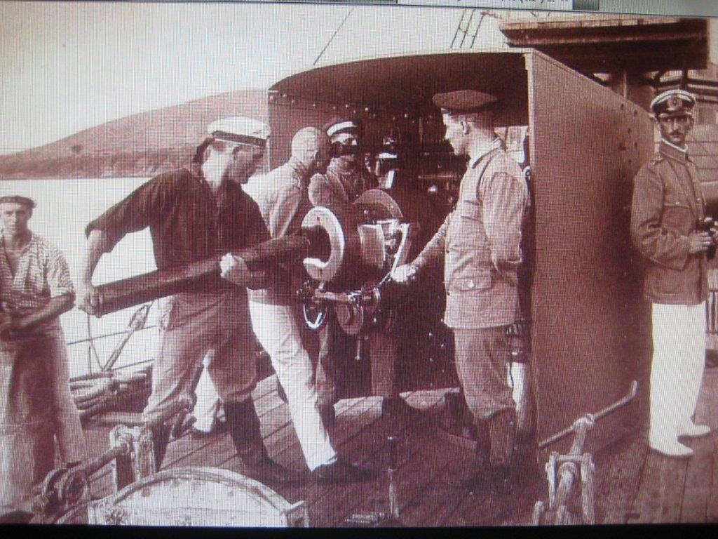
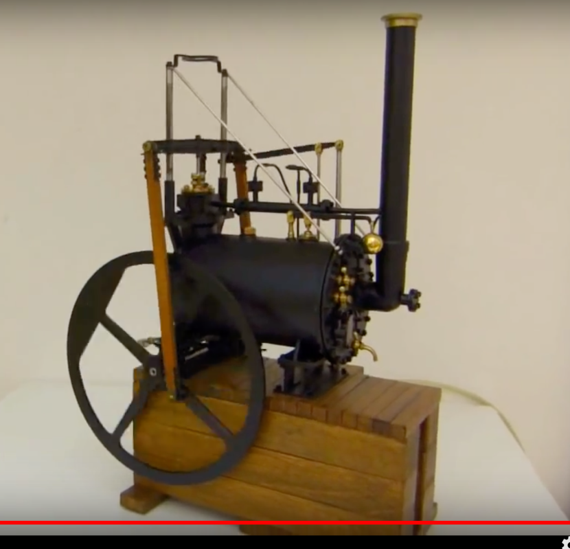
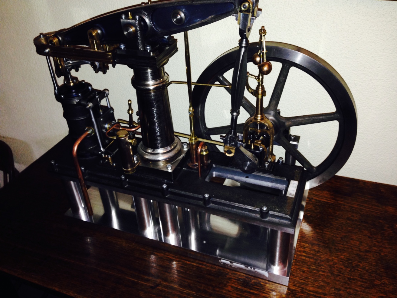
If you want to watch a video of a model cannon being fired, try YouTube. Or you could watch the following video, sent to me by one of my readers. This is a slightly larger scale than my model, and a breech loader. Superbly built. Click on the arrow to watch it.
When anyone finds out that I am building a model cannon, the inevitable question arises “are you going to fire it?”
Up until recently my answer was “no”, because, 1. I do not have a shooter’s licence, 2. I did not intend to register the cannon and 3. Australia’s gun laws which I support, are strict and policed.
If a model cannon is capable of being fired, it must be registered. As an owner built gun, it would have to be “proved”, i.e. be inspected by a gun expert, and have some proving shots with powder alone, powder doubled alone, powder plus shot, double powder plus shot, and finally double powder plus double shot. Then the gun is certified for the particular weight of powder plus shot. I think that I got that sequence right. It was explained to me by a gun testing expert recently.
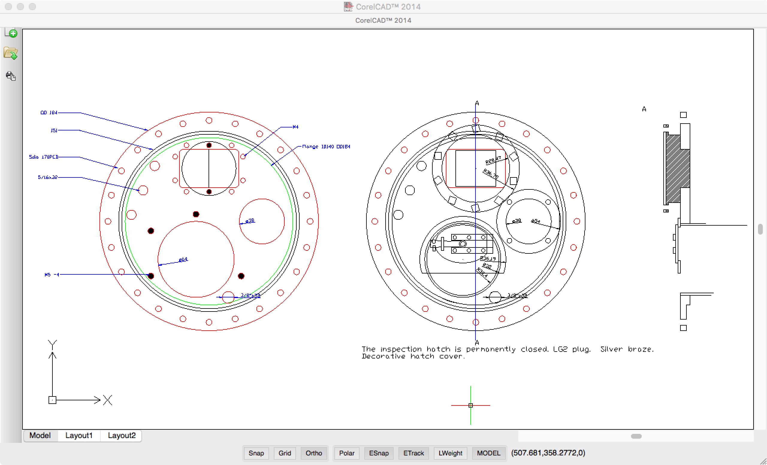
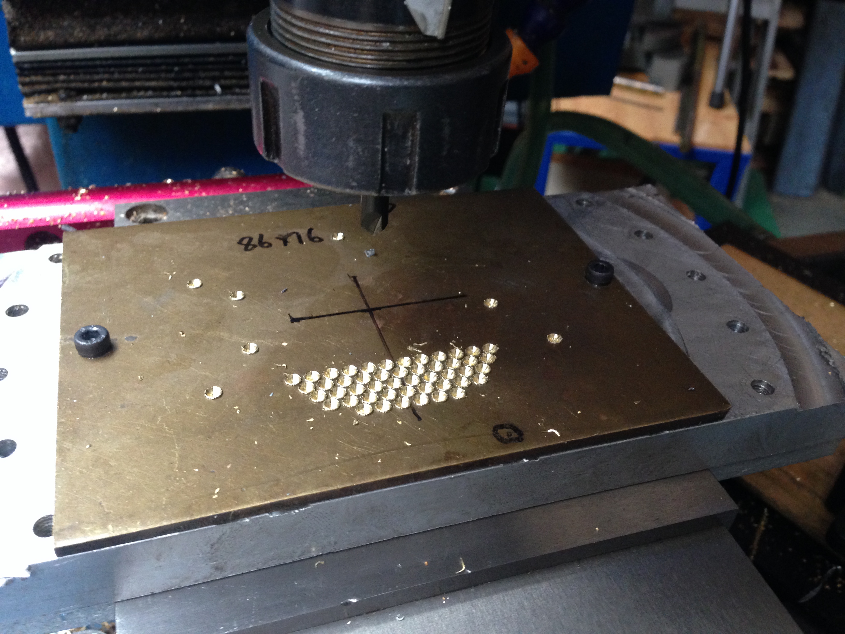
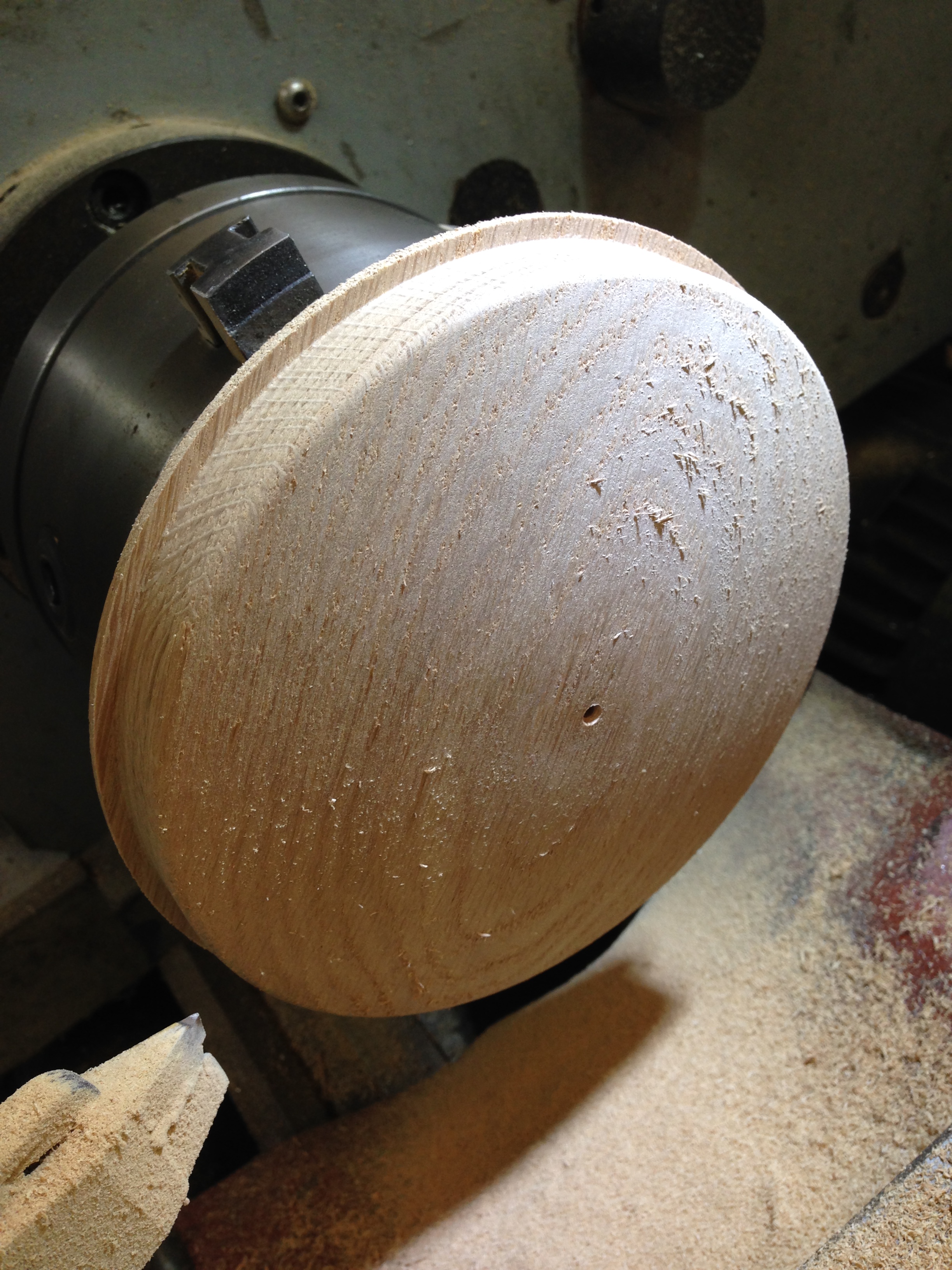
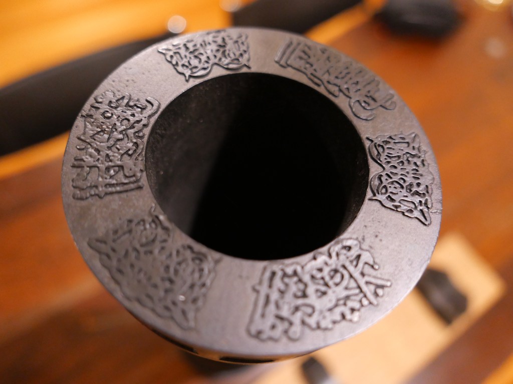
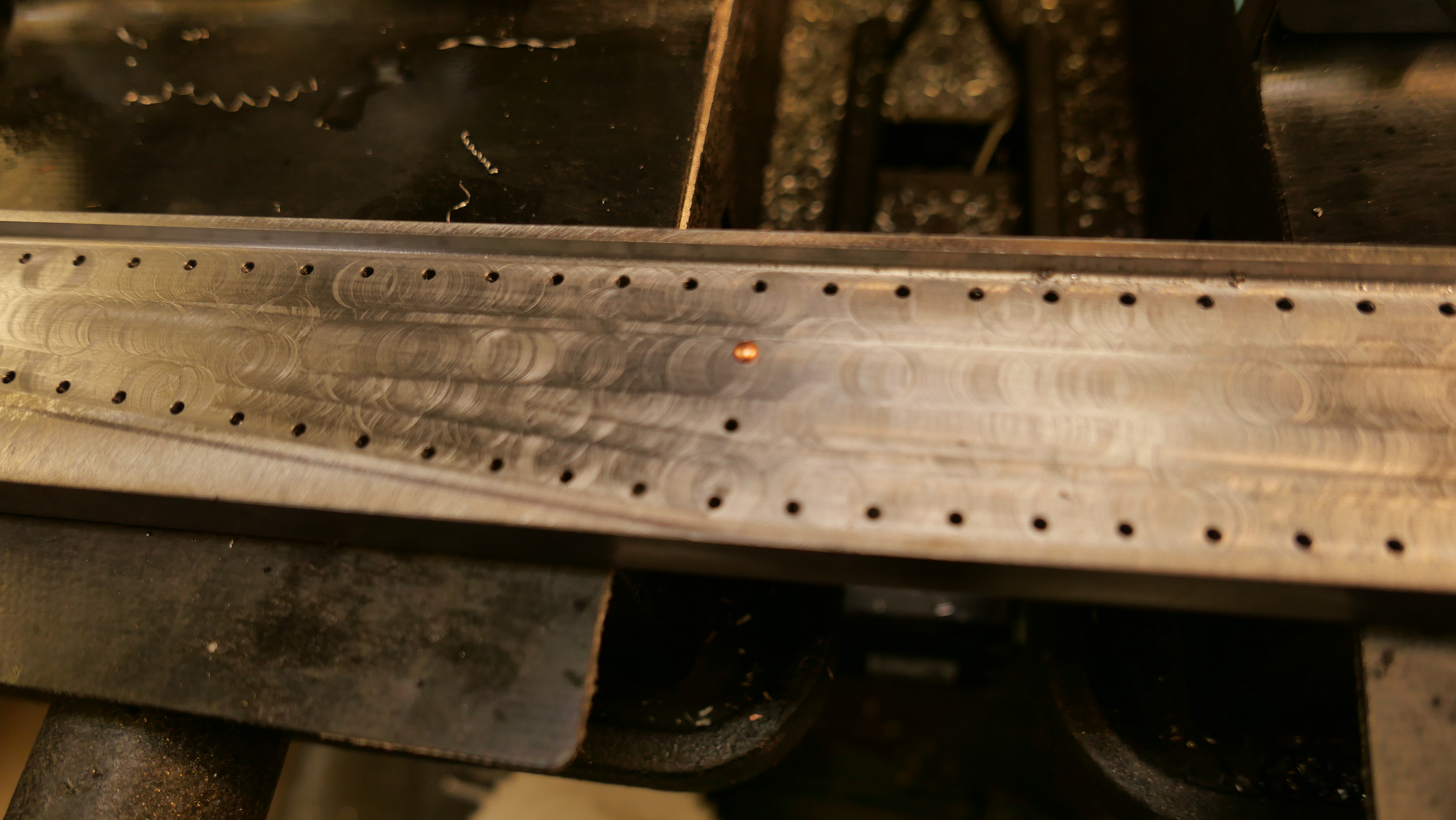
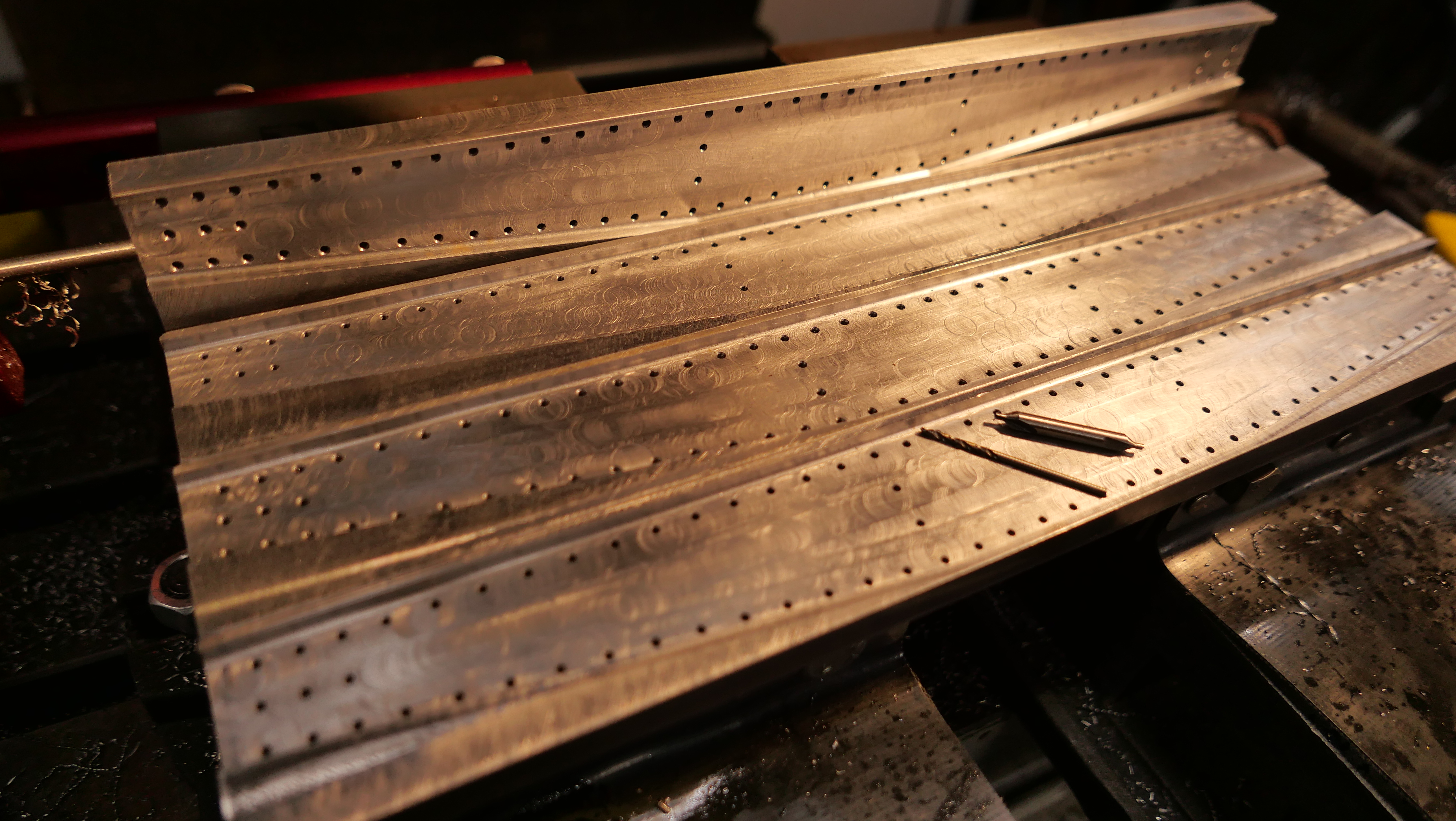
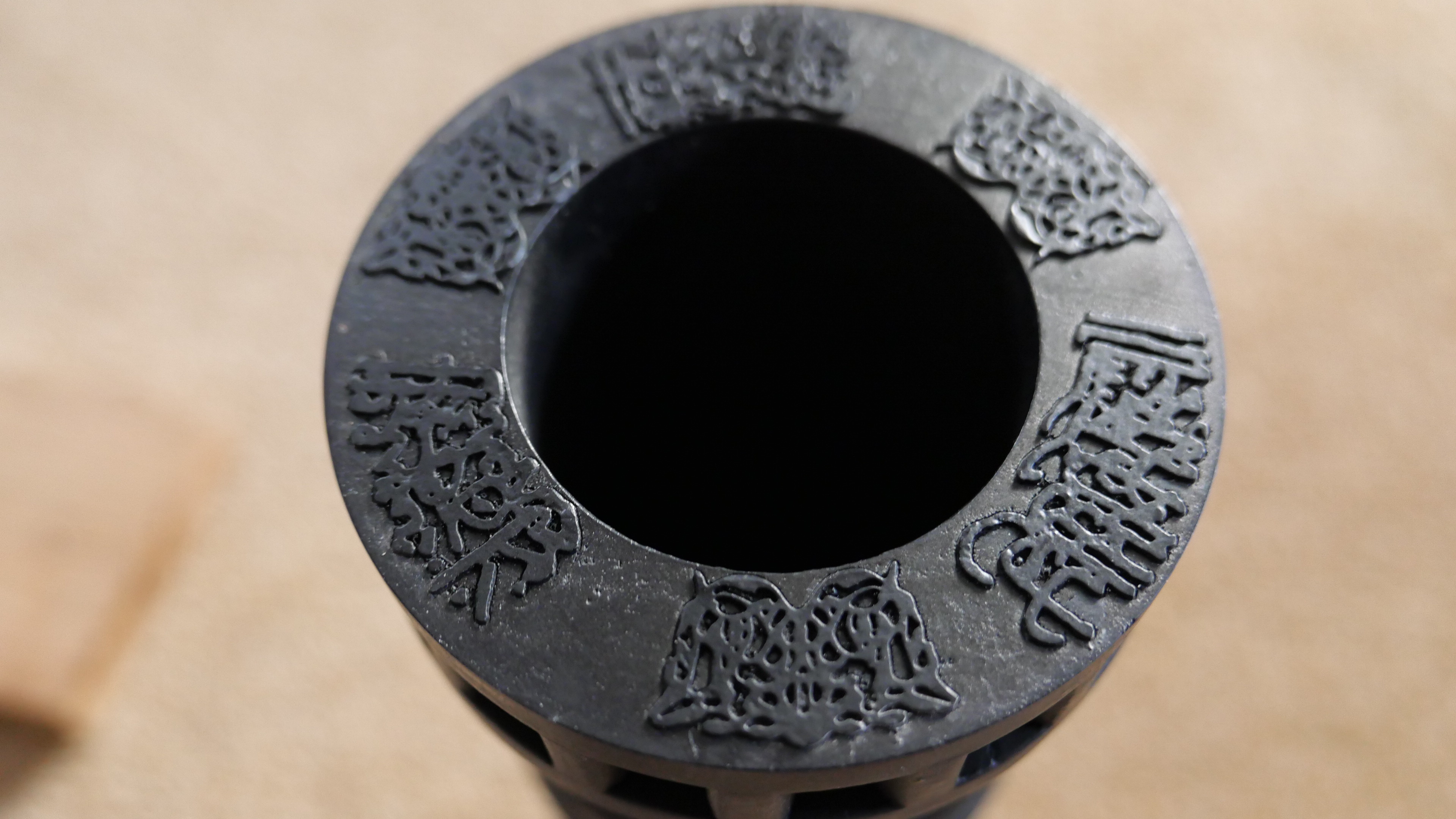
For a model cannon not required to be registered it must be incapable of being fired. For one such such as I am building, a muzzle loading, black powder cannon, that would mean not drilling the touch hole. In my case I could have the appearance of a touch hole, by making a dot at the site, but no drilling.
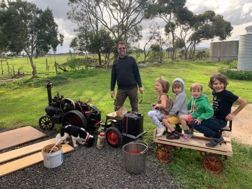
To investigate the situation, I have checked the Victorian Government website, spoken to police, and spoken to a firearms safety course instructor. I also visited a shooting range where a blackpowder gun club was having a target shoot. Members were shooting black powder guns and rifles at targets 50-100 meters distant.
About 50 years ago I was in the Citizens Military Forces, a university infantry company, and had instruction and practice in using a 7.62mm SLR, an F7 submachine gun, and an M60 machine gun.
My point is that the black powder guns were VERY loud. Painfully loud in fact, until ear plugs were fitted. Substantially louder than I remembered SLR’s, F7’s or M60’s. But maybe I have just forgotten. And the blackpowder shots were accompanied by a gout of flame, and a large puff of smoke. Spectacular, in fact.
Then, under the close supervision of a gun owner, I fired a black powder hunting rifle myself. It was loaded by the owner, using a ram rod for the charge, and a mallet then ram rod for the ball. 2 triggers. The first was a heavy pull to ready the shot. The second was a hair trigger to fire it. And hair trigger it was. Just a touch and it fired. Despite the BANG, some fire and smoke, and the instantaneous puff of dirt where I had aimed, the recoil was minimal, more of a firm push against the shoulder. It was an interesting and exciting experience. Less smoke and flame than the other blackpowder guns nearby, but maybe being a hunting gun, he had used a more modern powder. The following short video shows my son in law taking instruction.
I have put in an application for the firearms safety course which is supervised by the Victorian Police. Then there is a 2 part multi choice examination, with no incorrect answers permitted on critical questions, and 18/20 (I think) for the rest. If passed, there is a criminal history check, and references required. Then a compulsory 4 week wait.
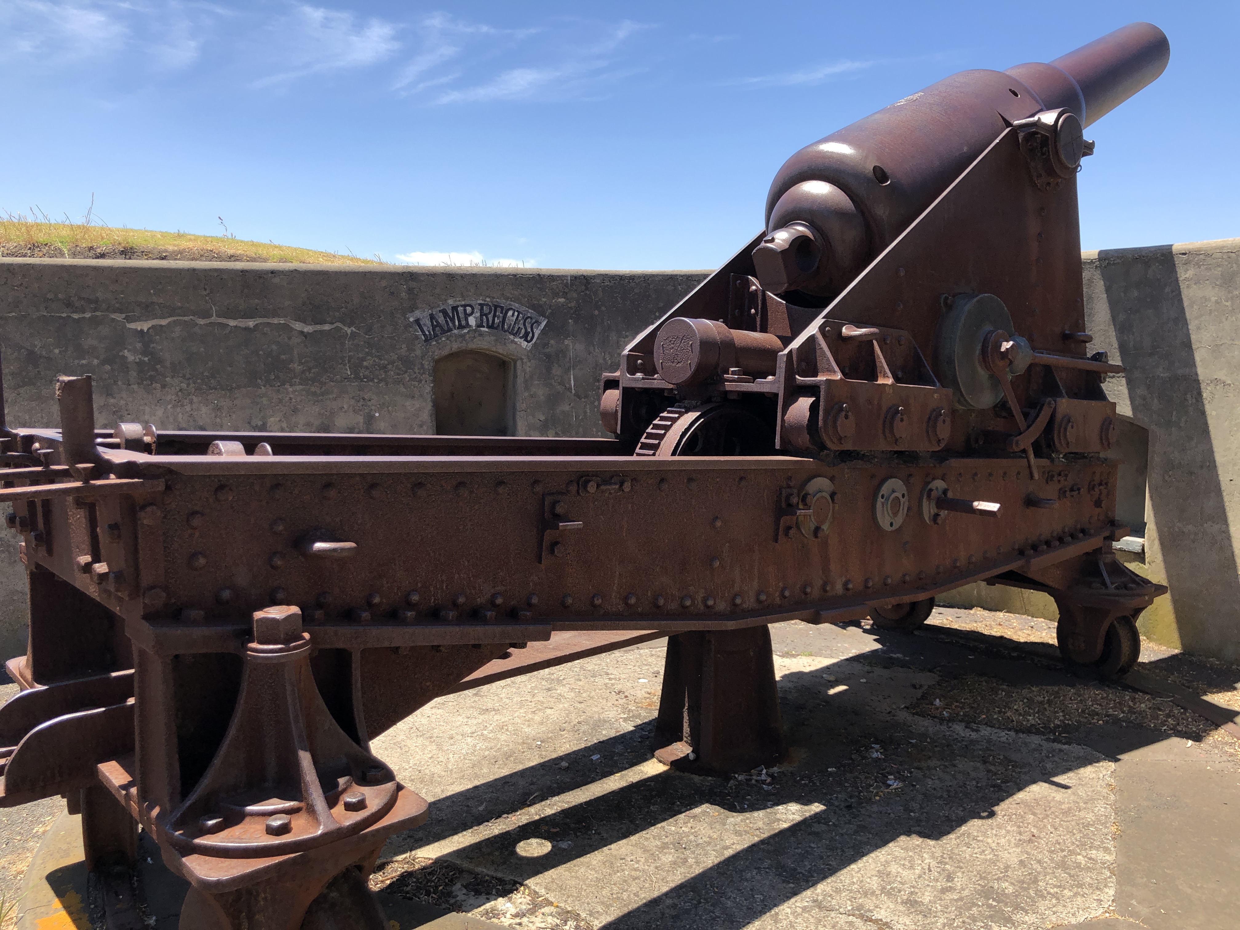
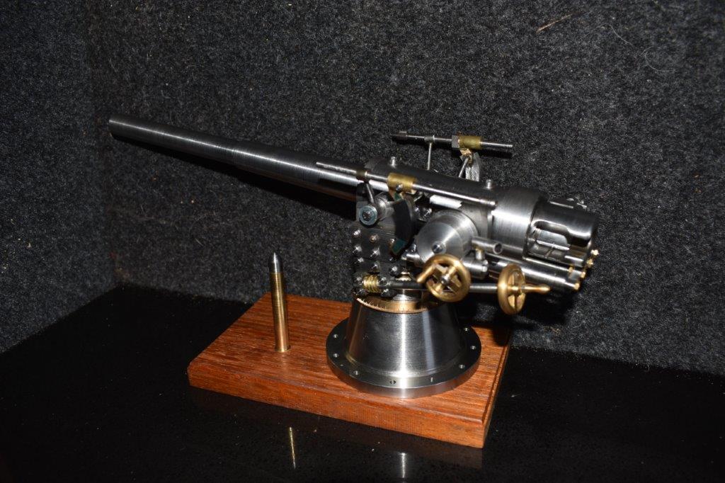
I will get the shooter’s licence, to keep my options open, but have not yet decided about registering the model cannon. It would be nice to have a video of it being fired, for this blog, but it is very likely that it would be a once only event. My interest in the cannon is its historical associations, and the technology, plus the challenges of building it.
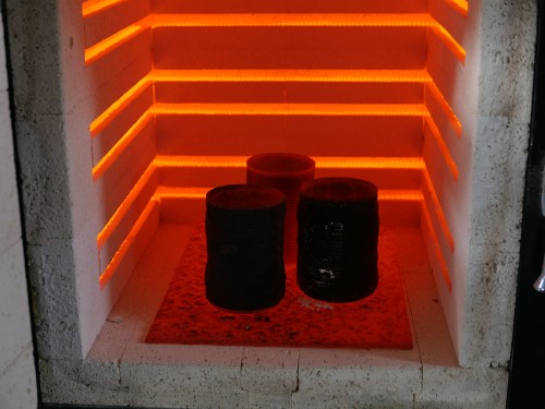
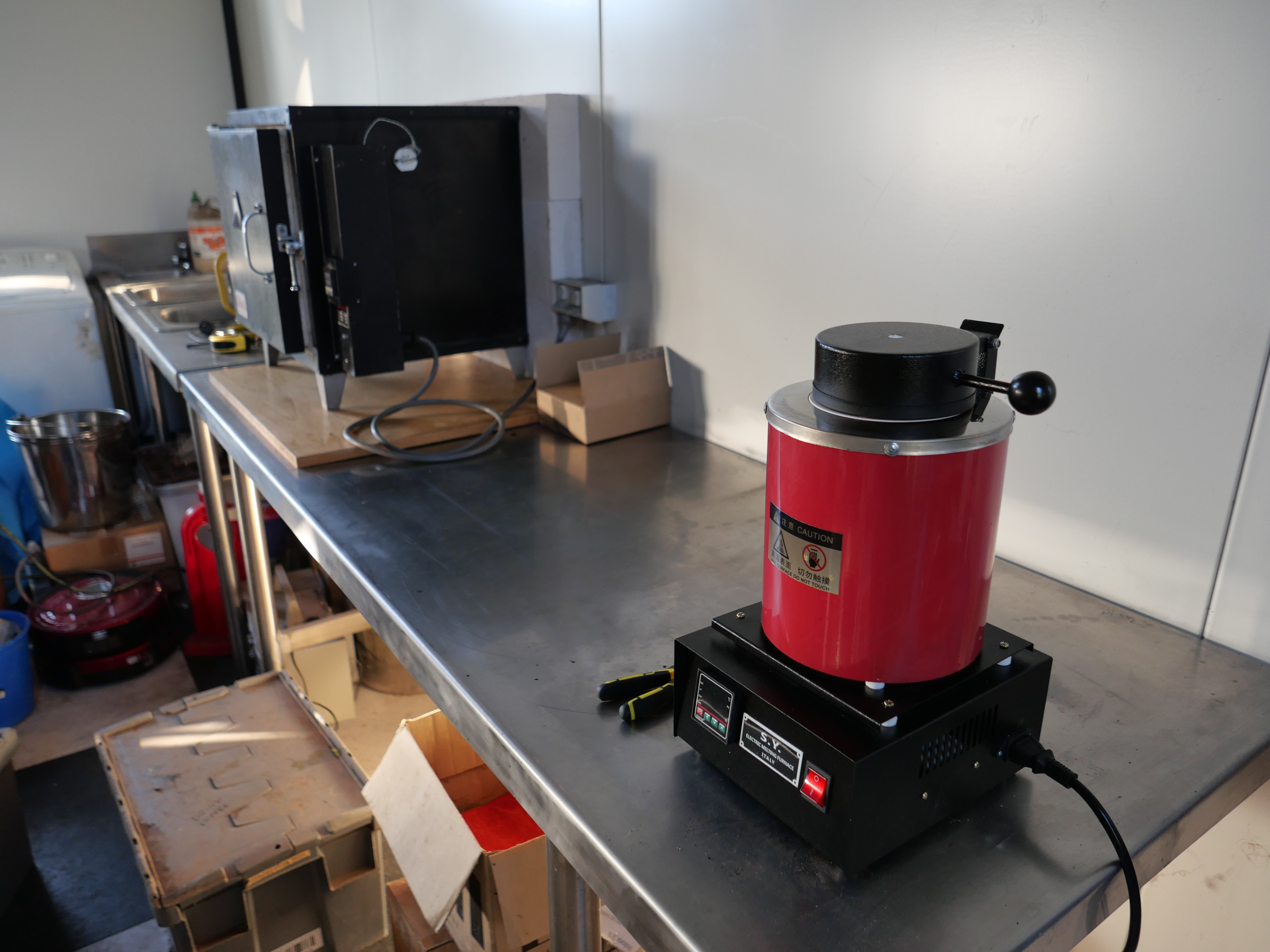
If the cannon is capable of being fired, it would have to be registered indefinitely, and the owner would need a shooters licence. After all of the time and effort in its research and construction I would hope that someone in my family would eventually own it, so I am thinking that I will not make a touch hole, and make it incapable of being fired. Another possibility which I will explore, is to register the cannon, make a video, then make it incapable of being fired by partly filling the bore and touch hole with molten metal then deregistering it.
Meanwhile it will have no touch hole.


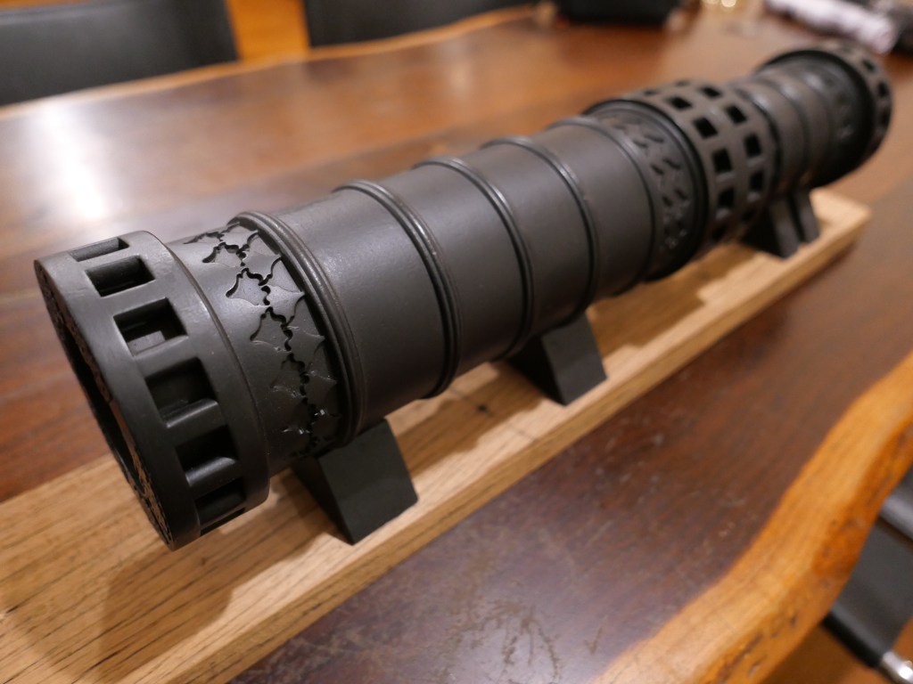


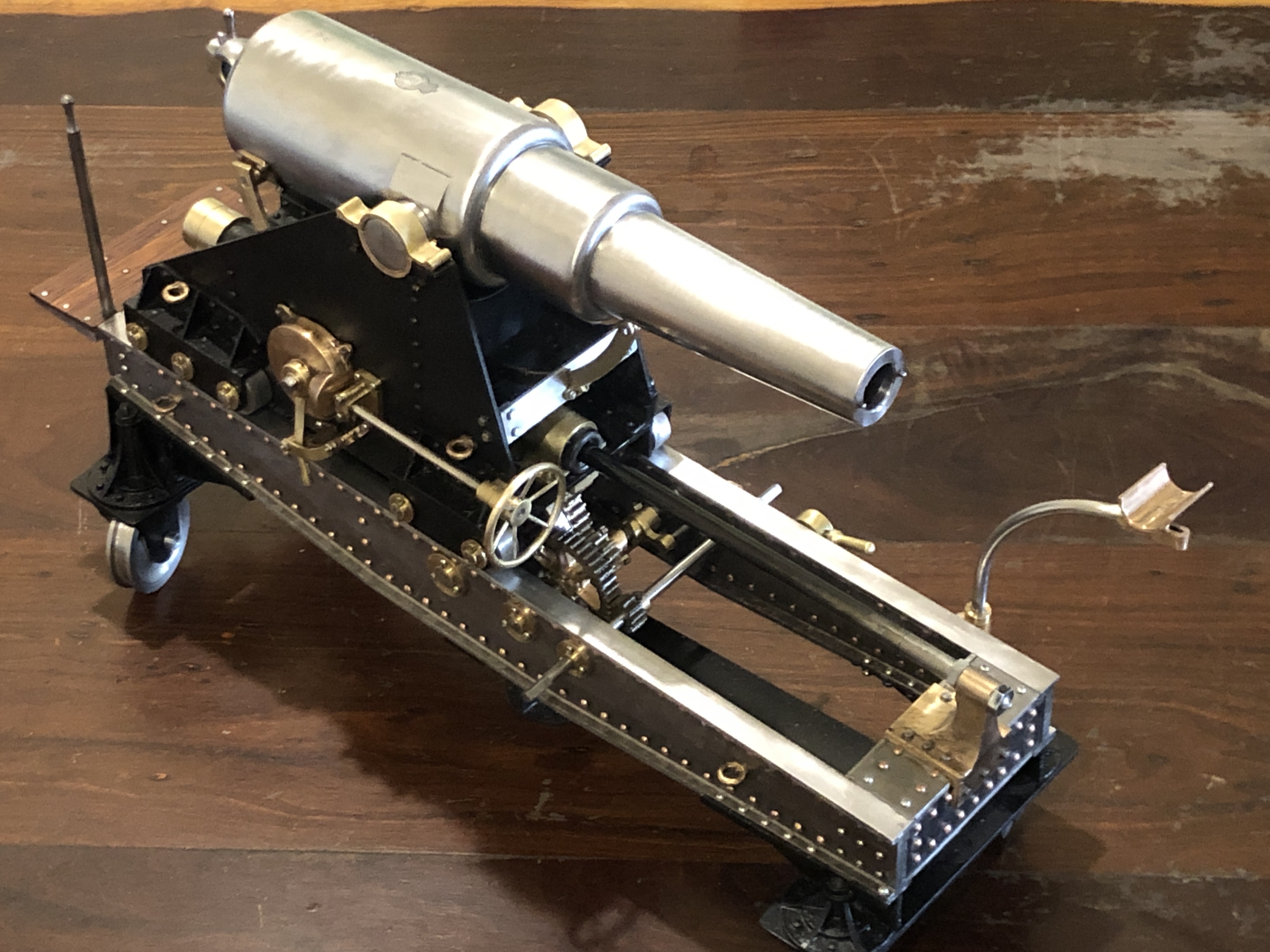


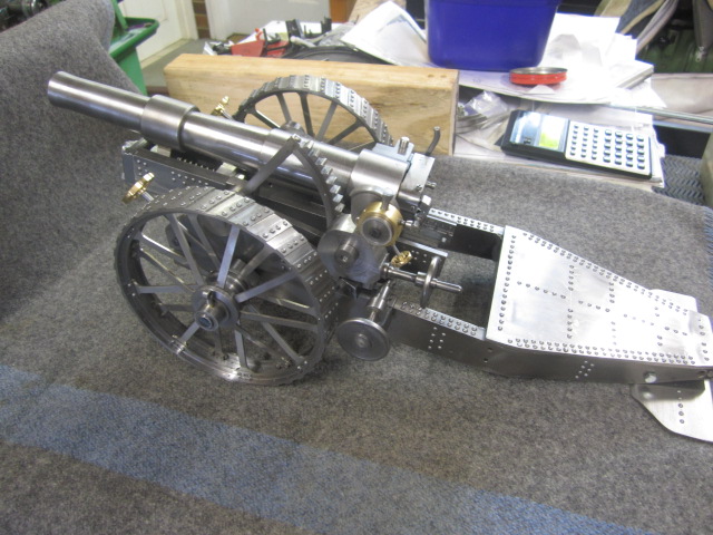


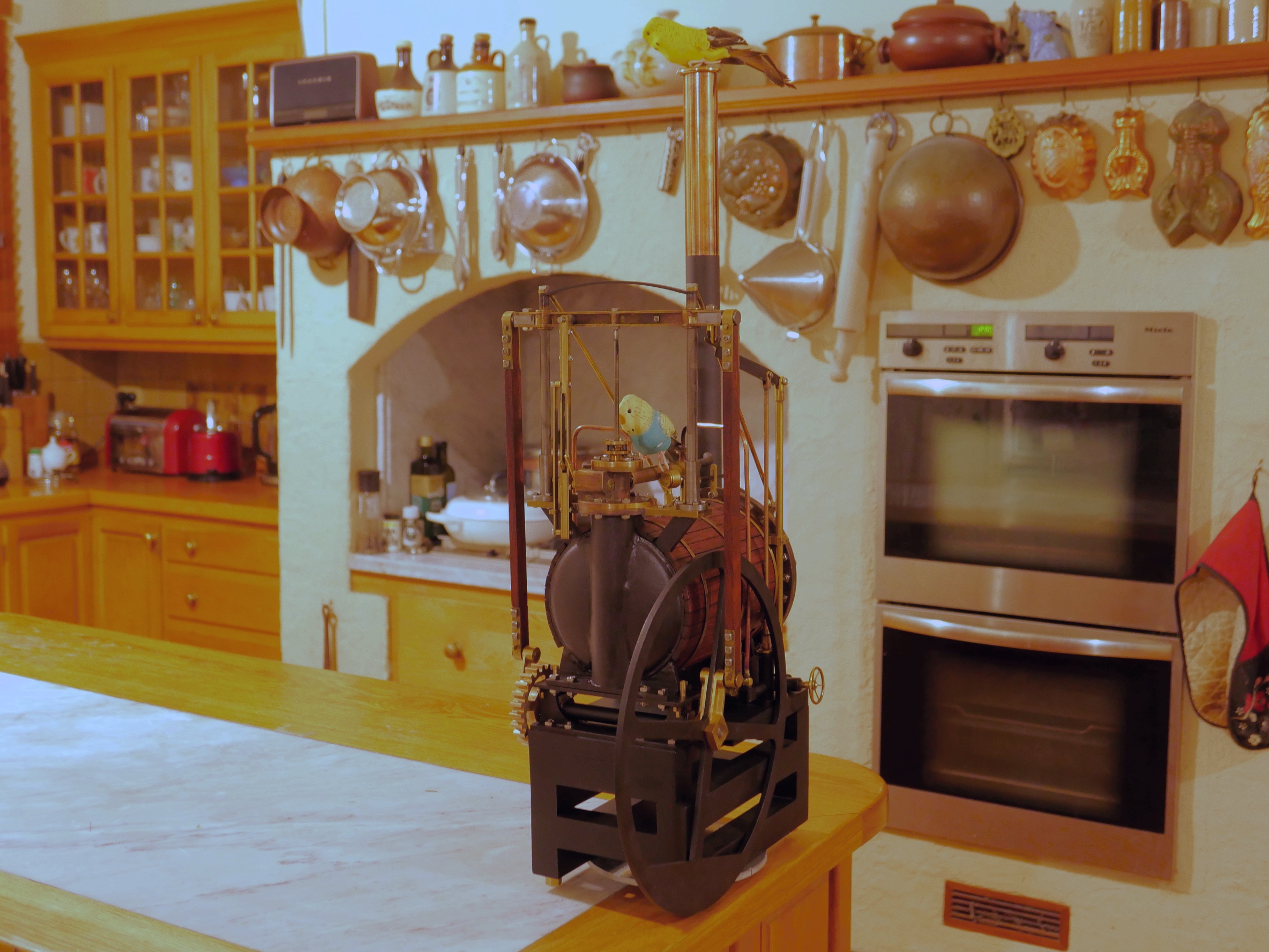

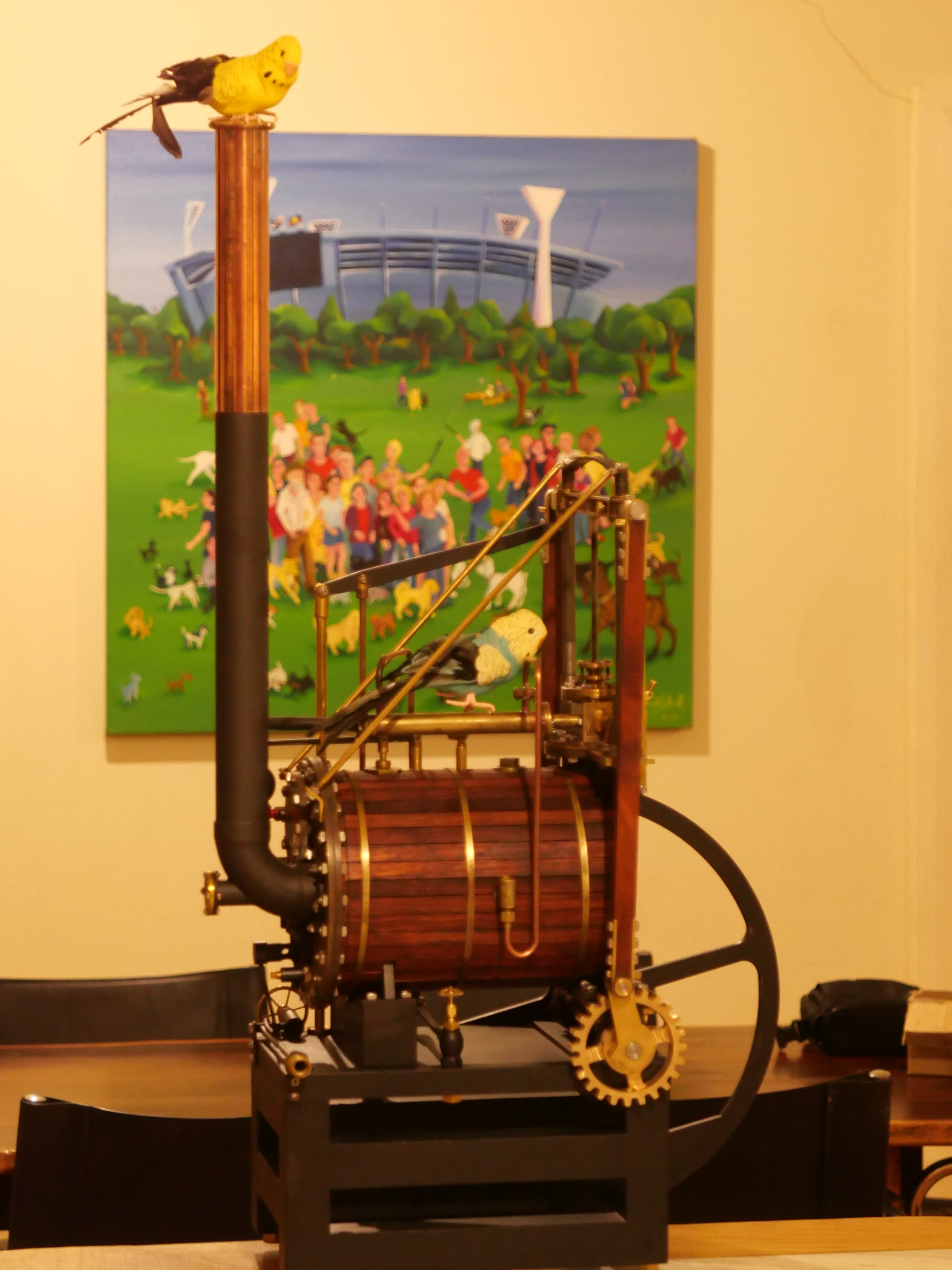


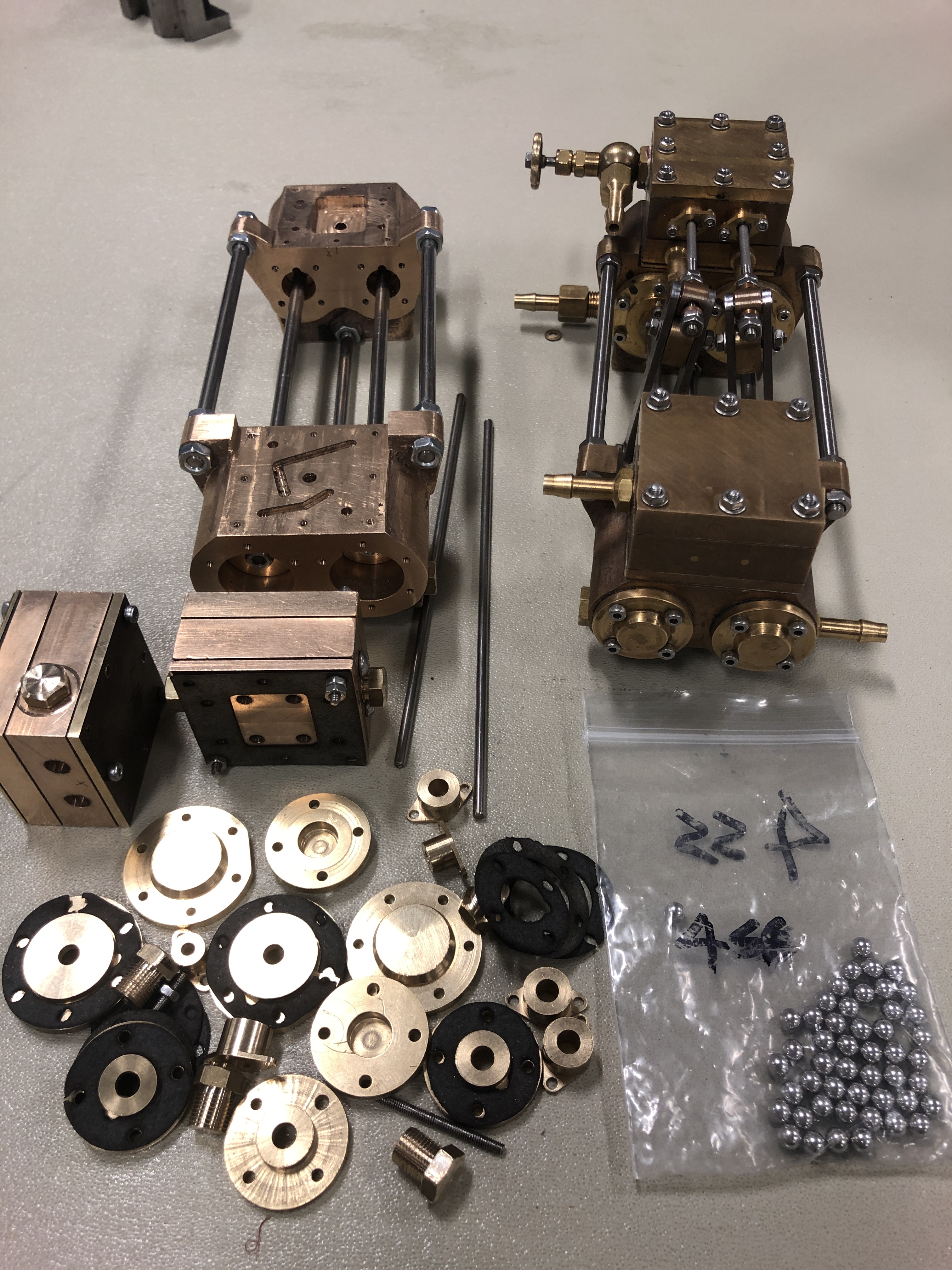


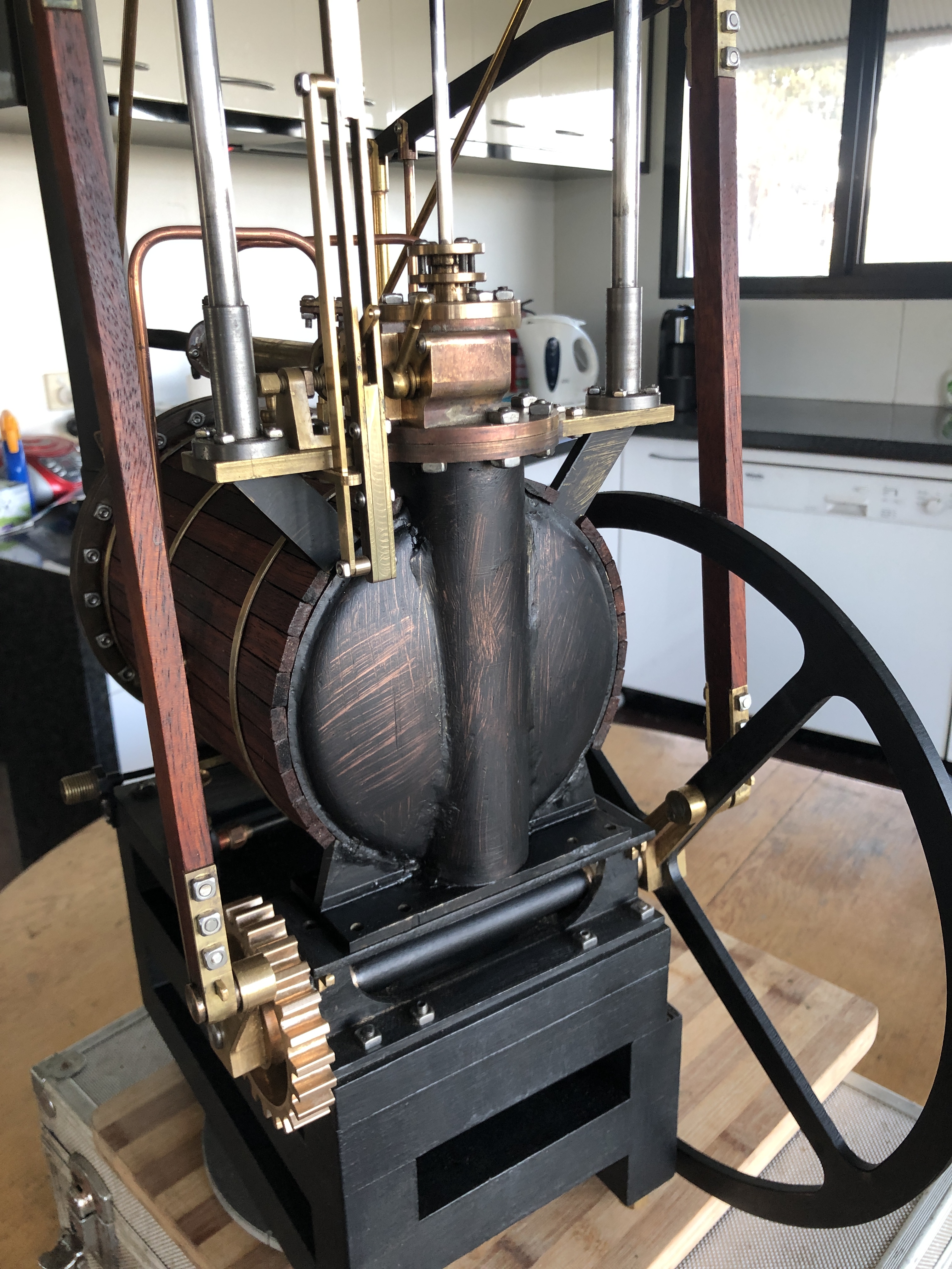


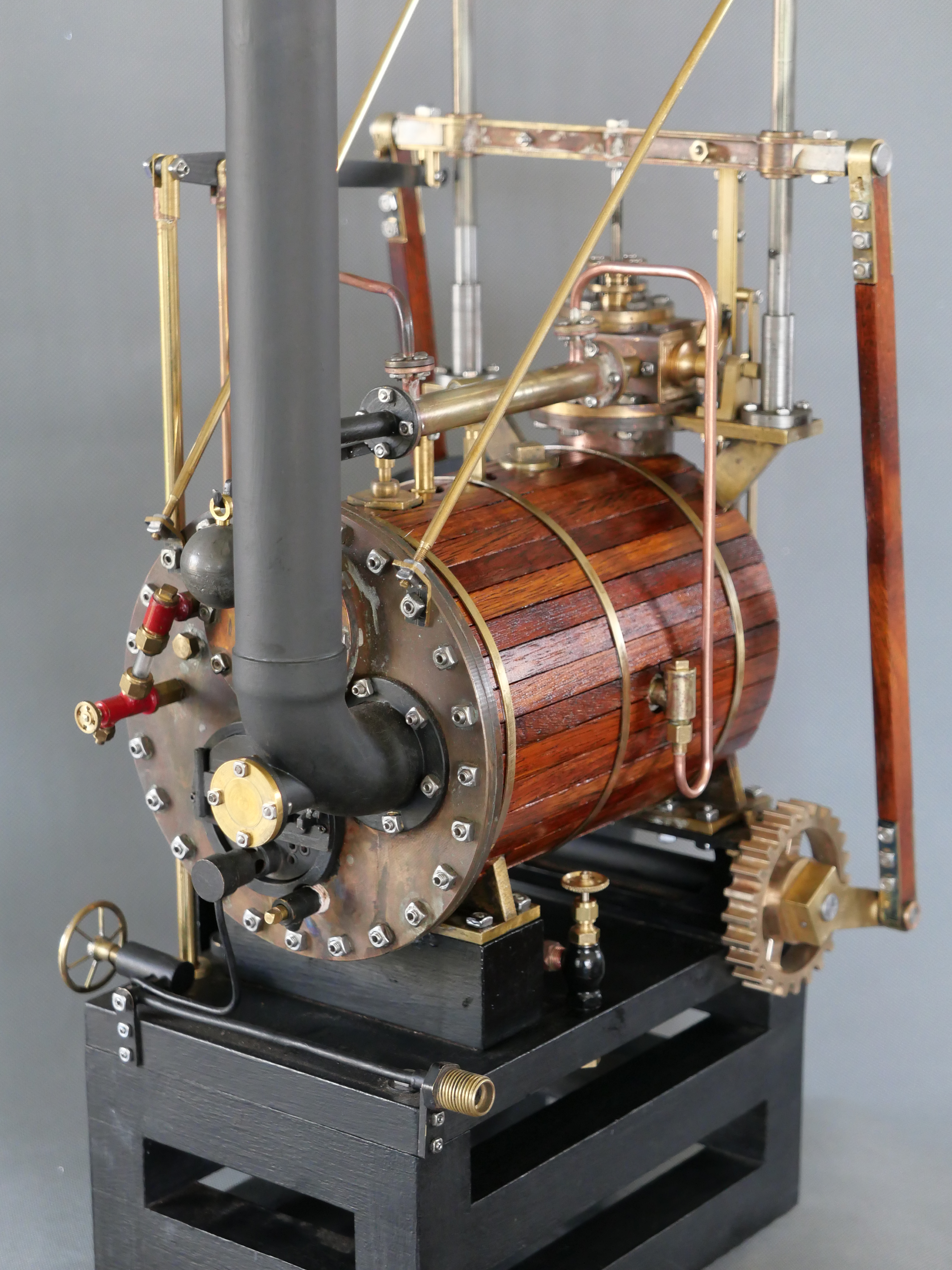


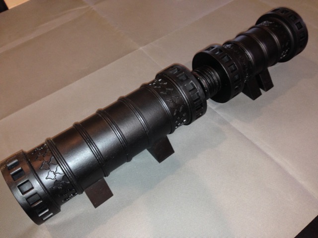
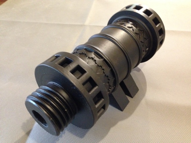
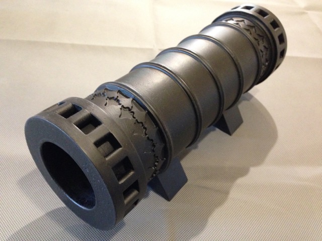


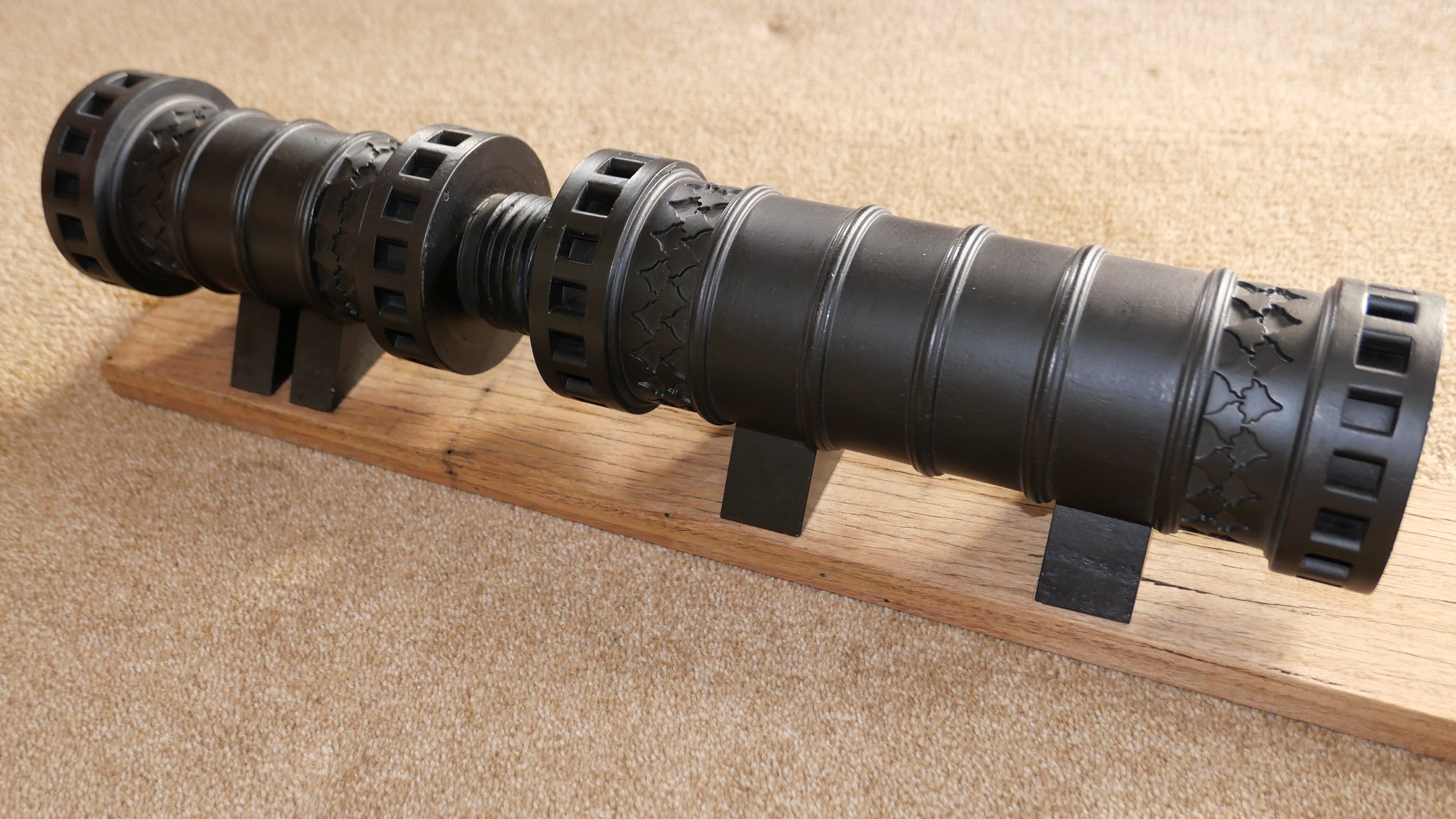

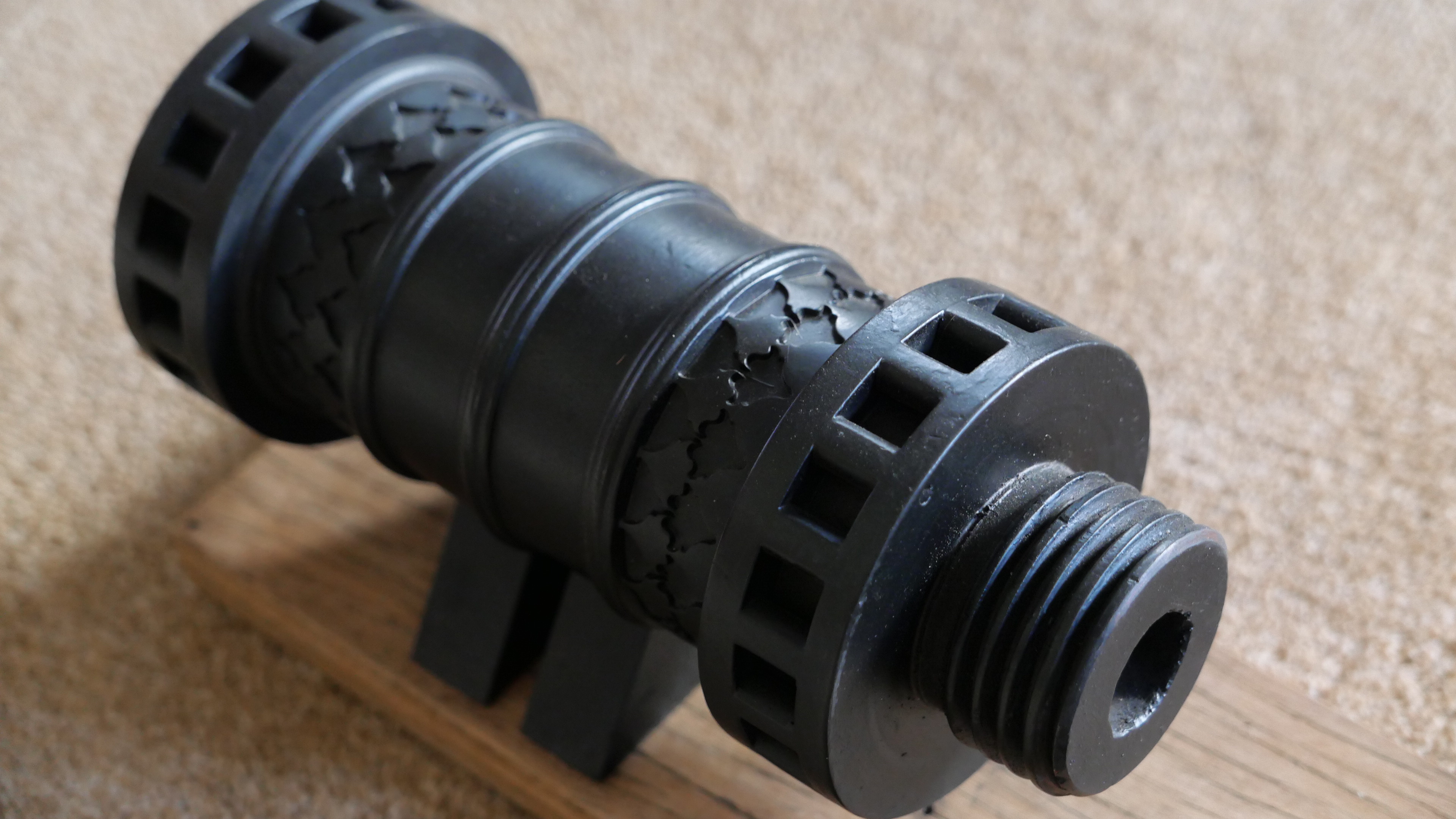


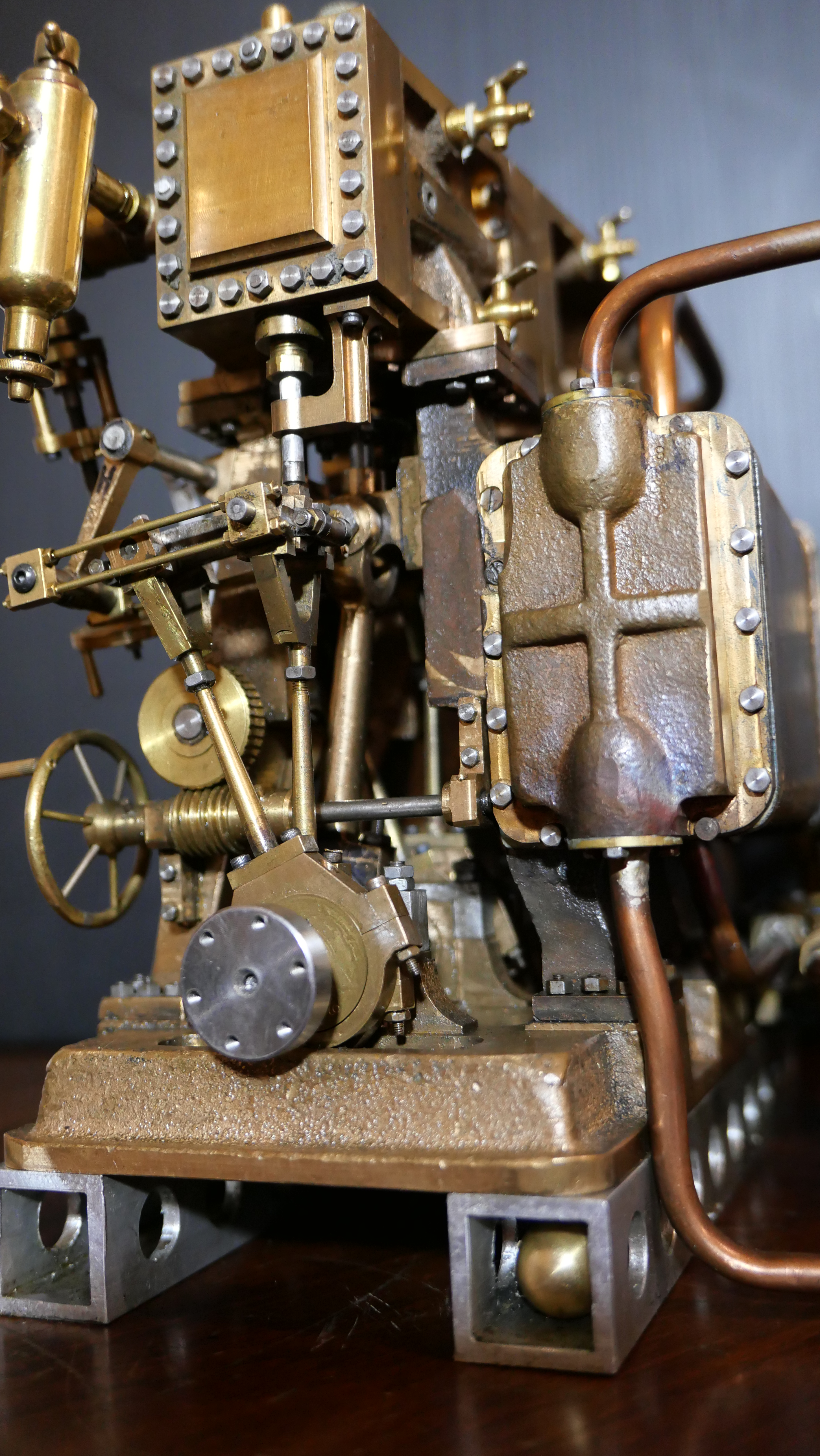


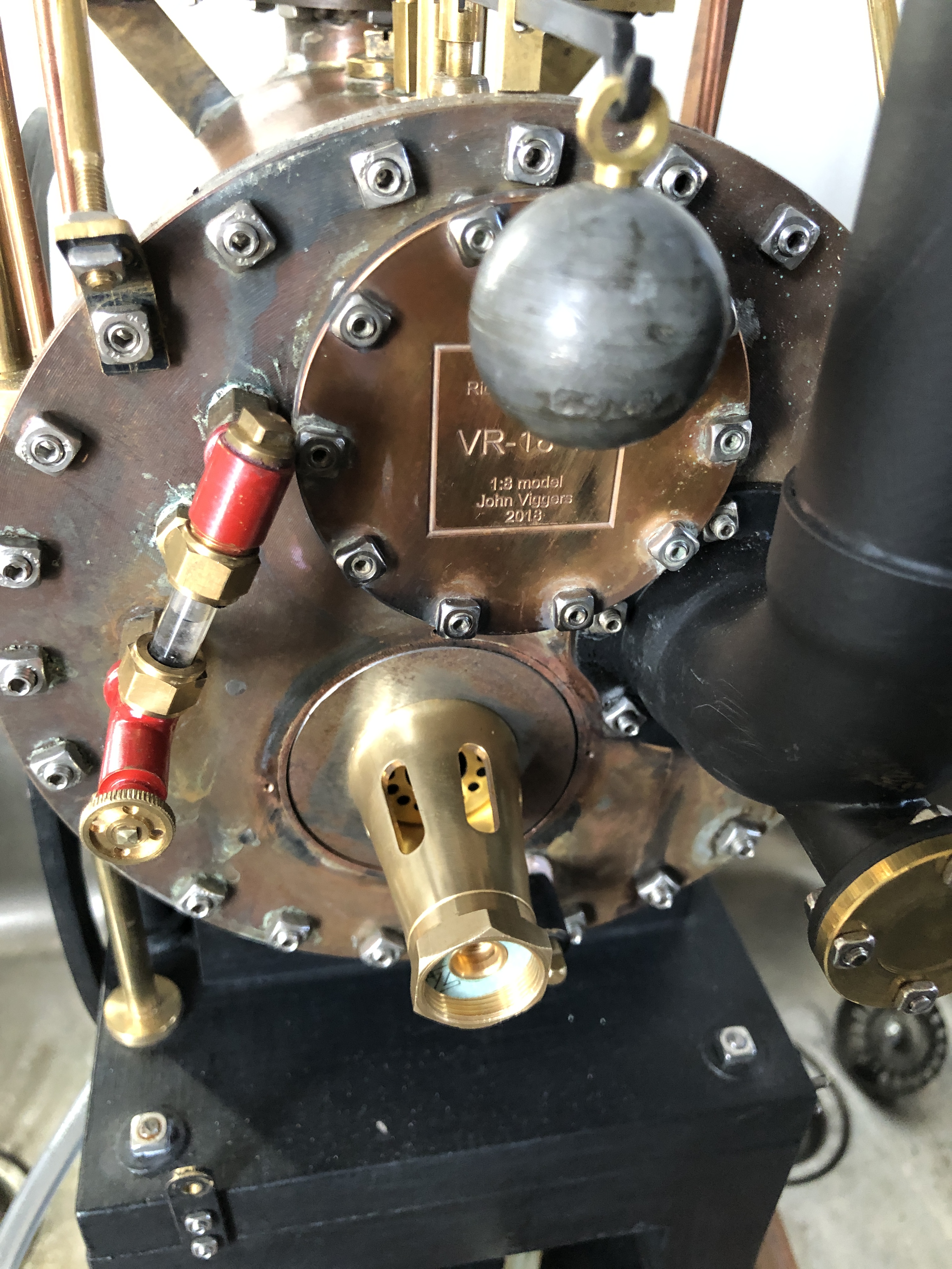


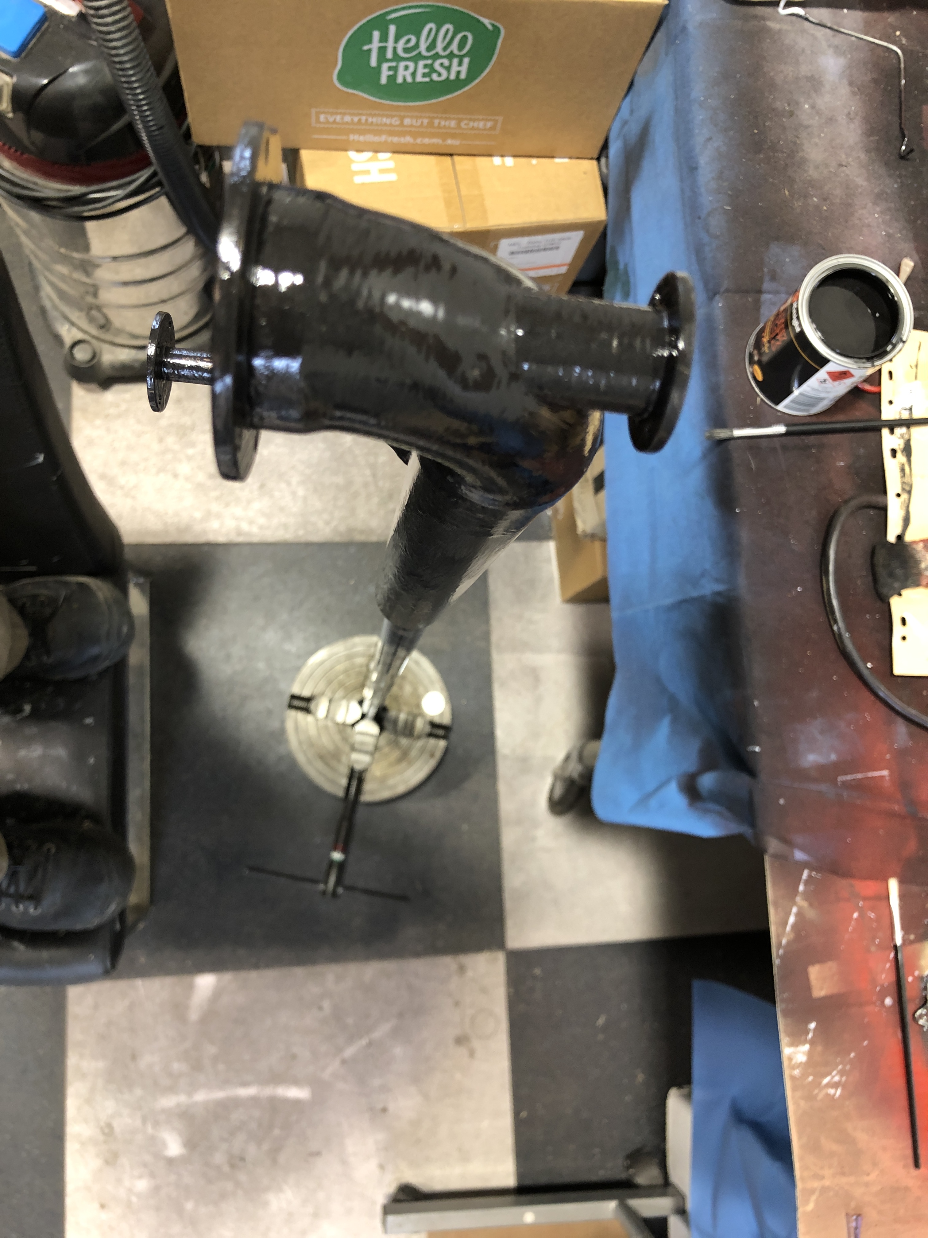
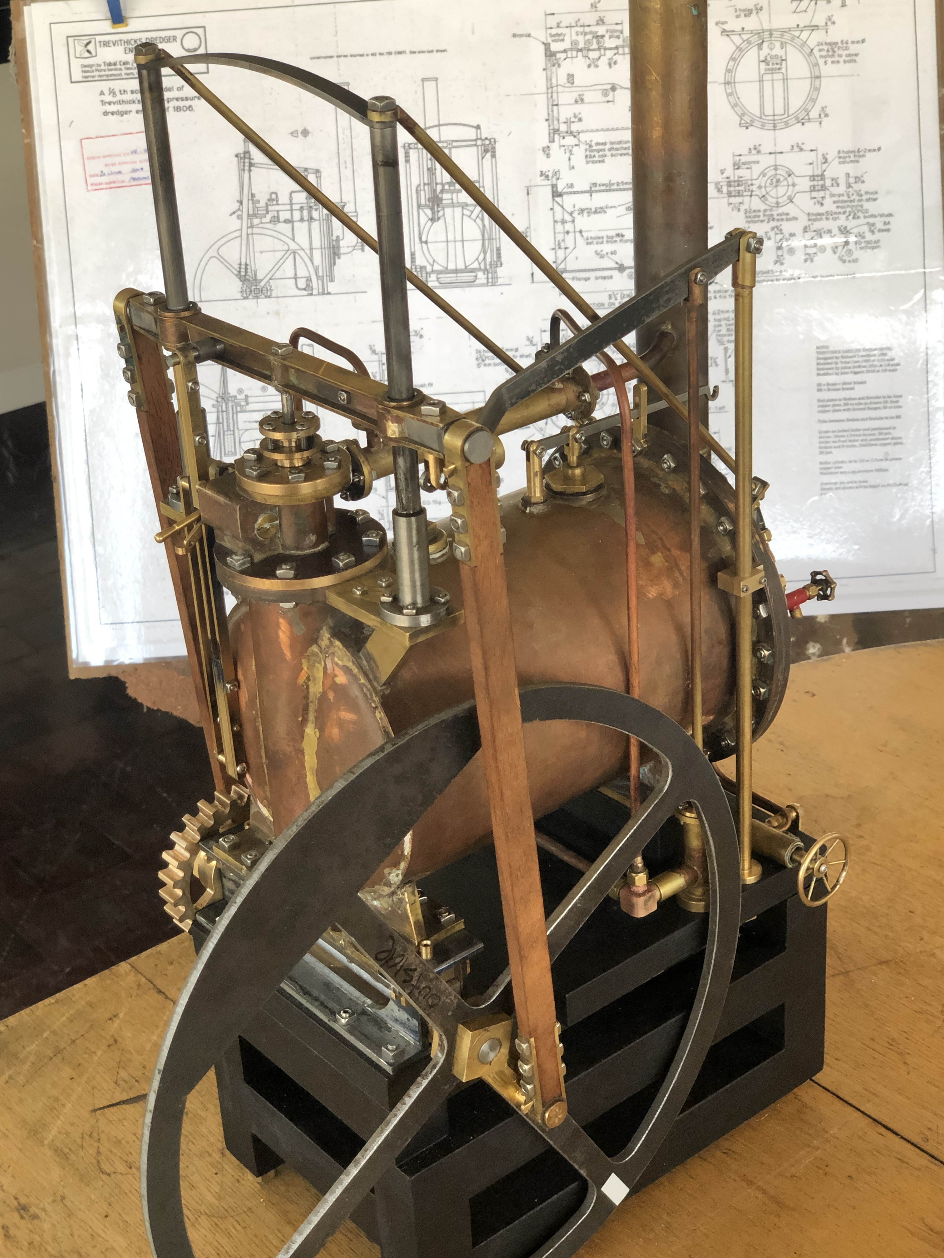
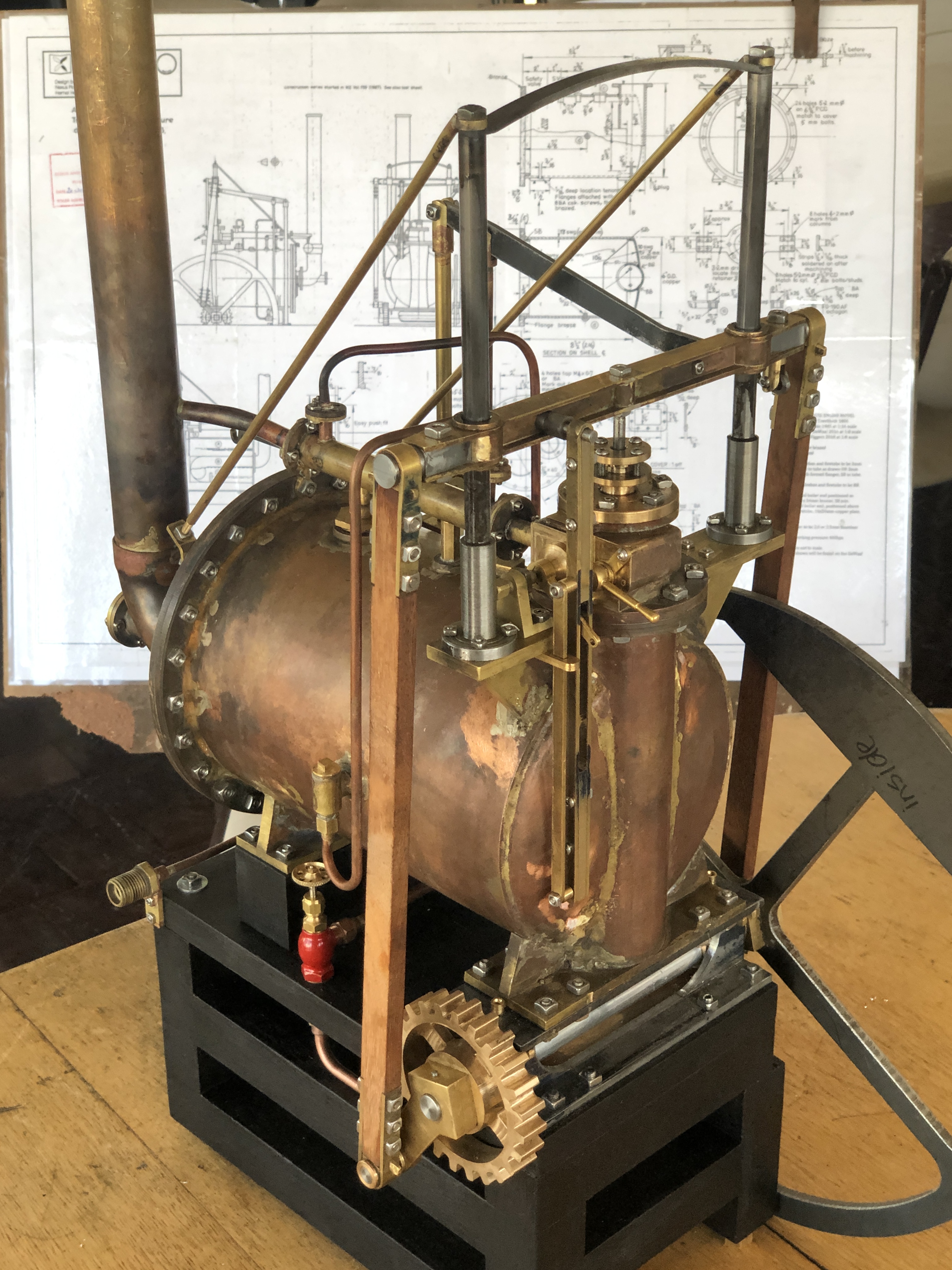
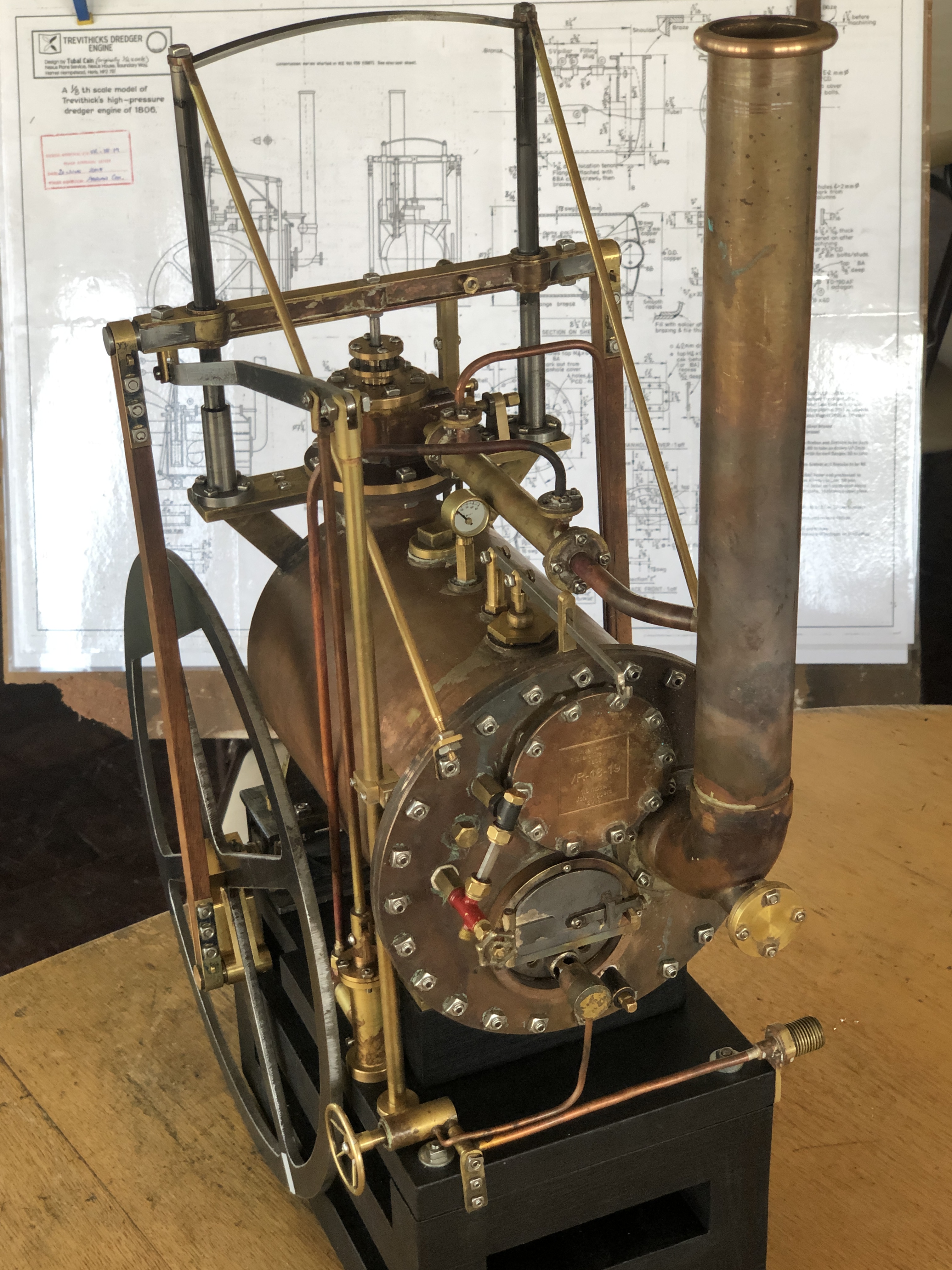


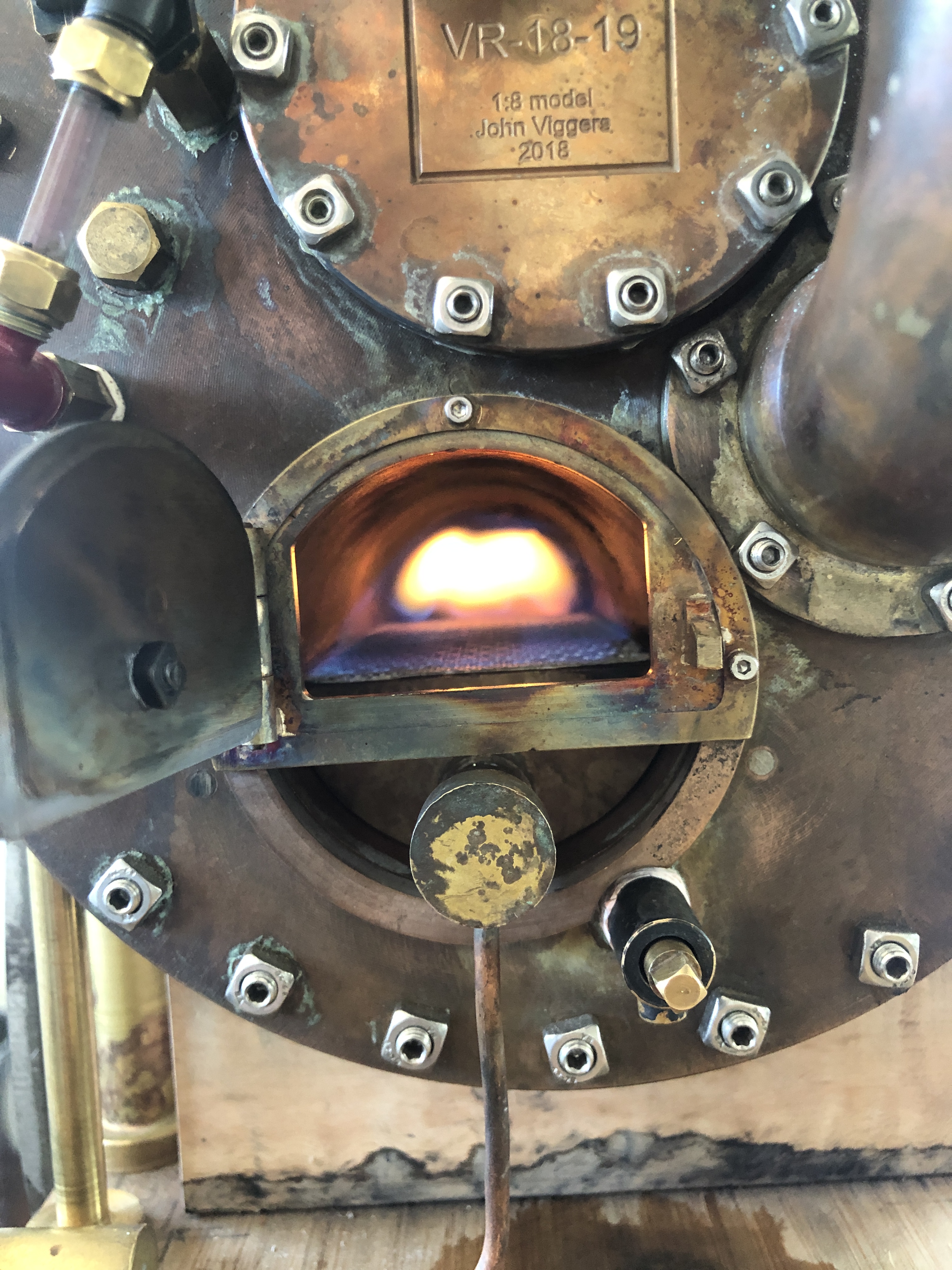


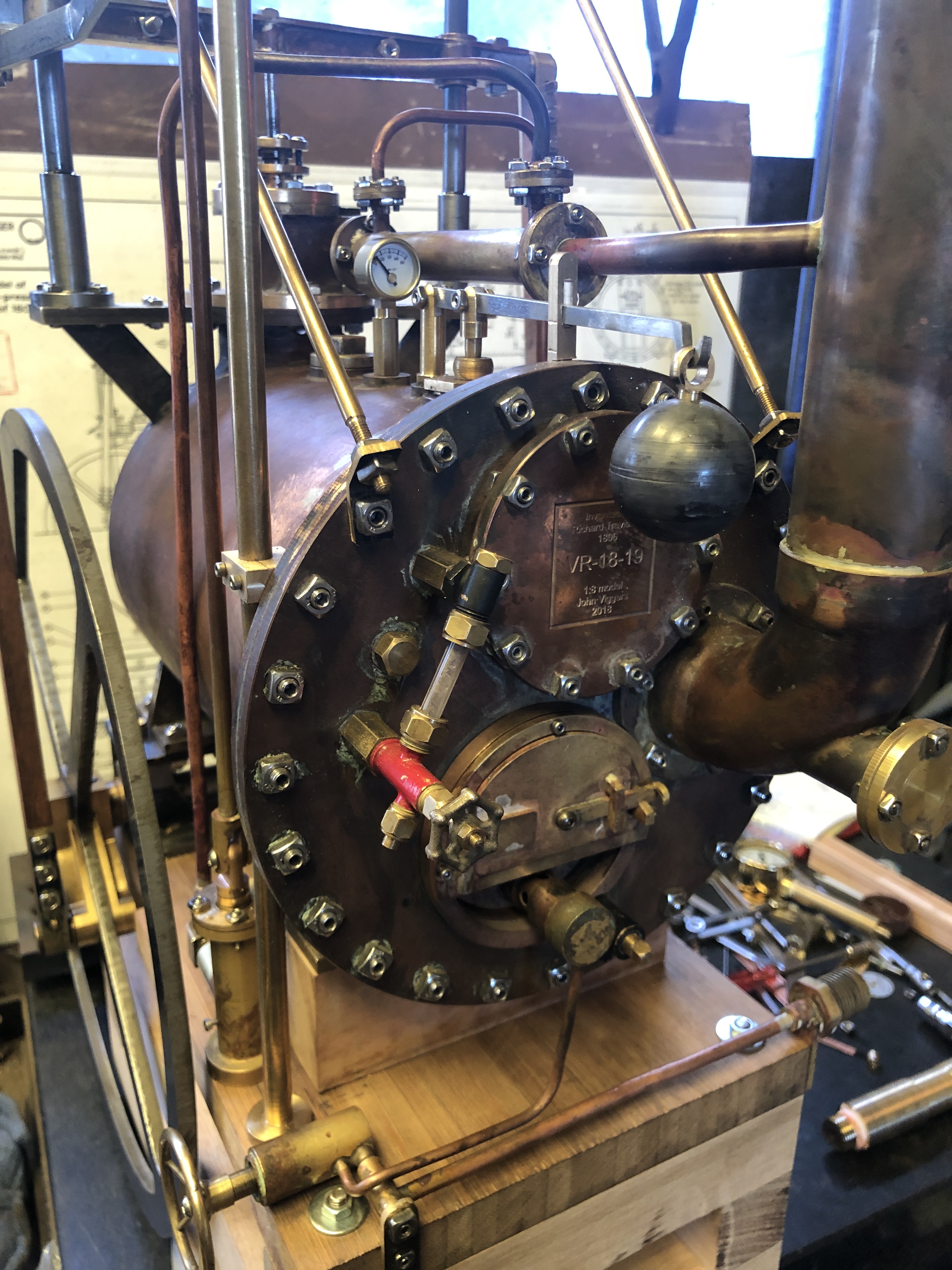

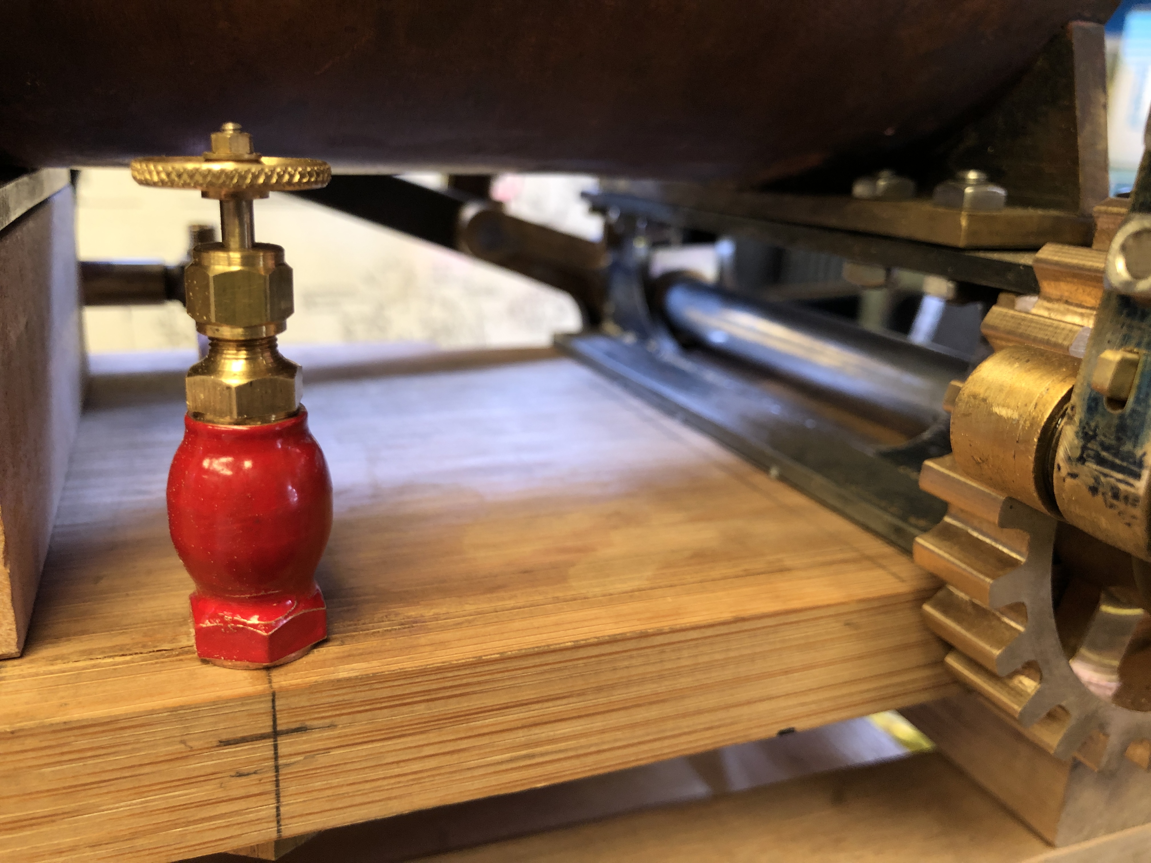
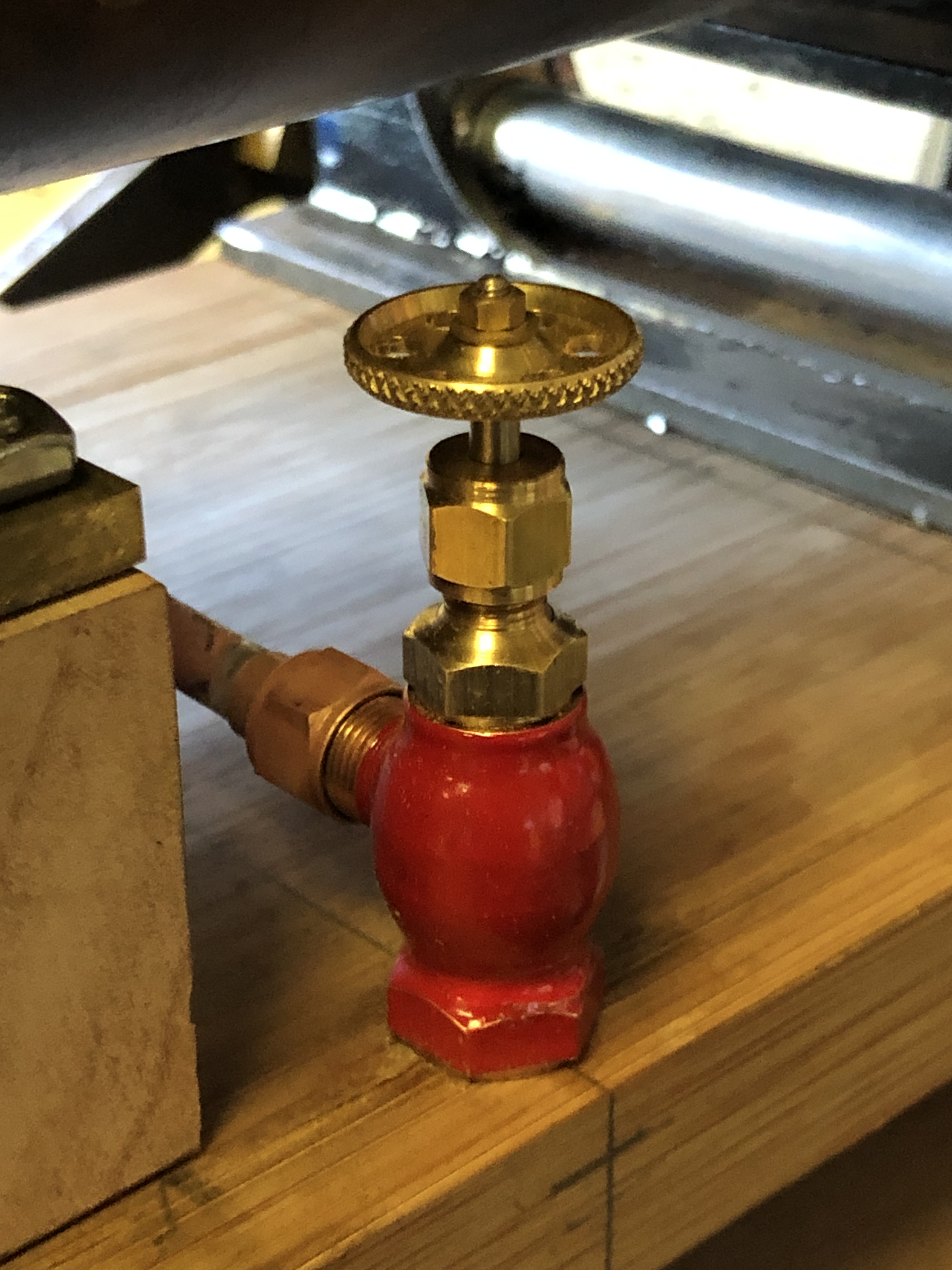
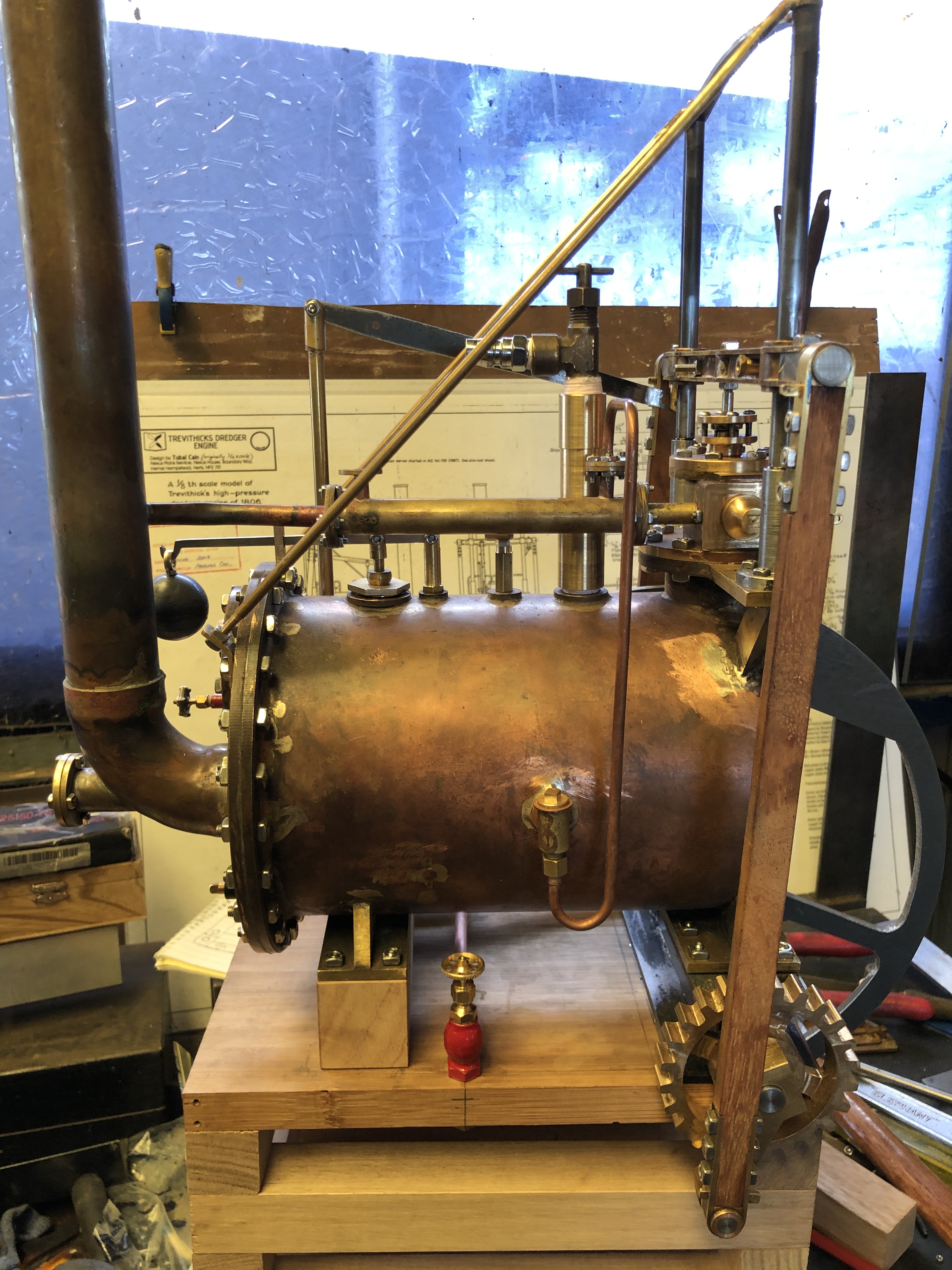


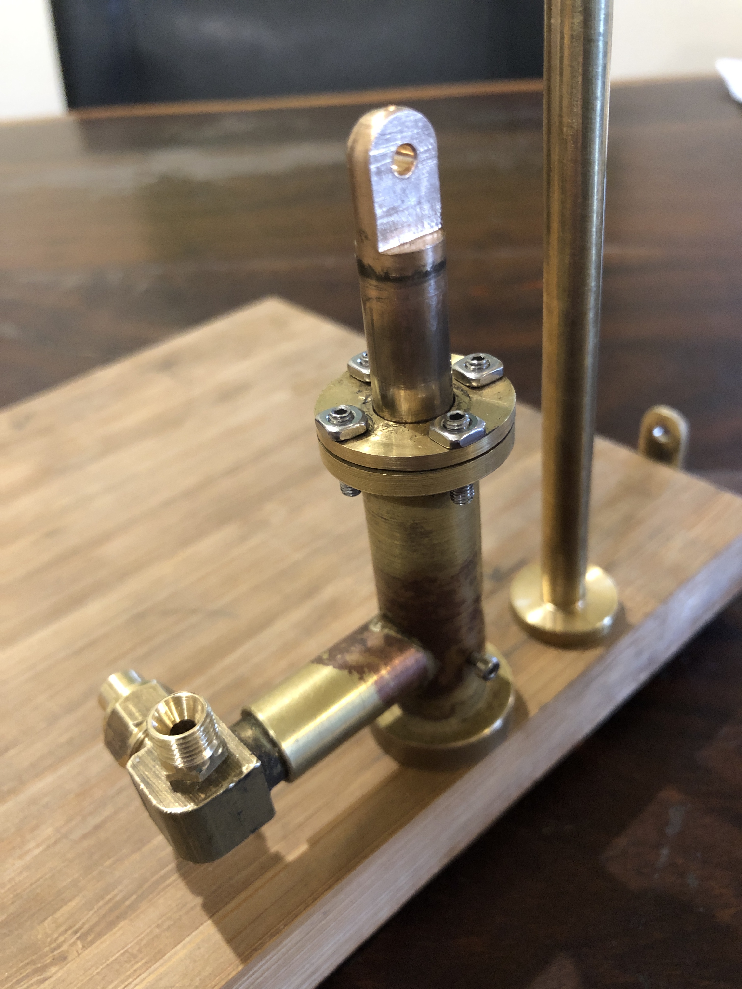
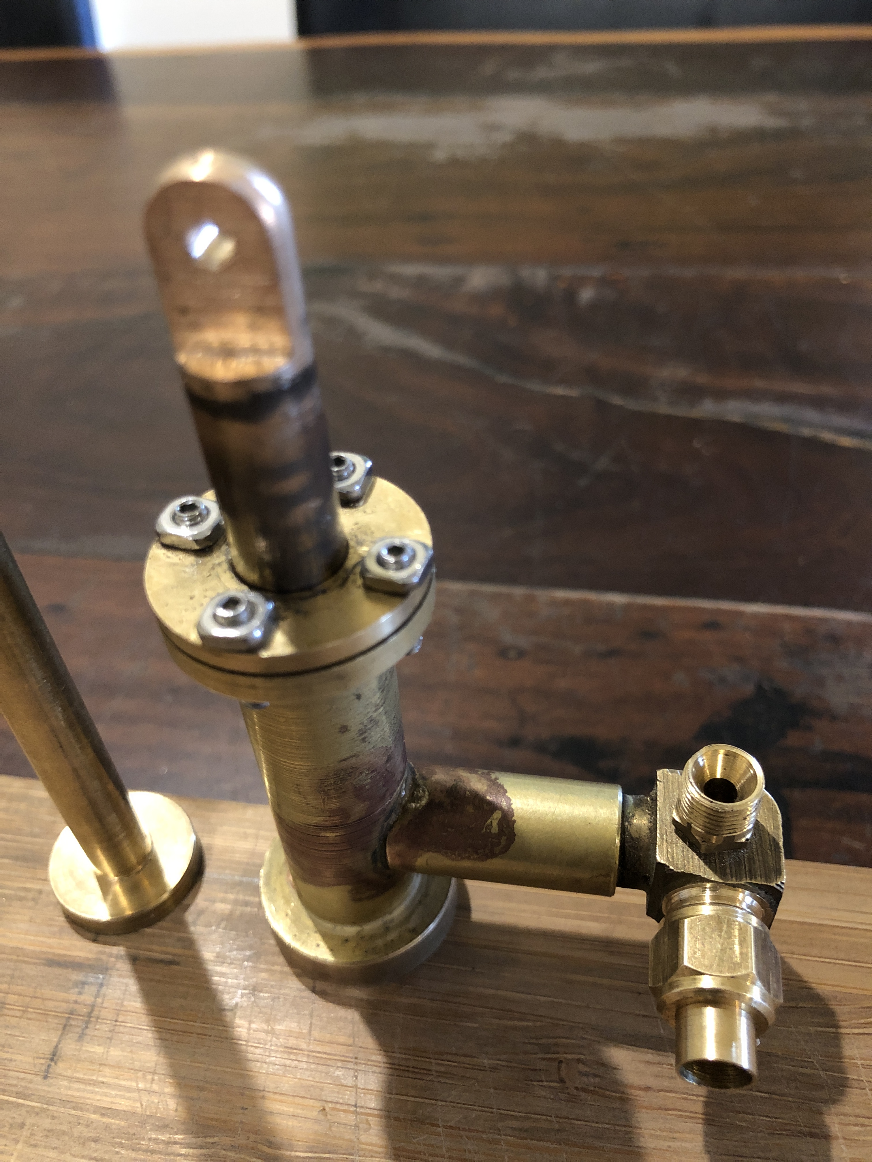


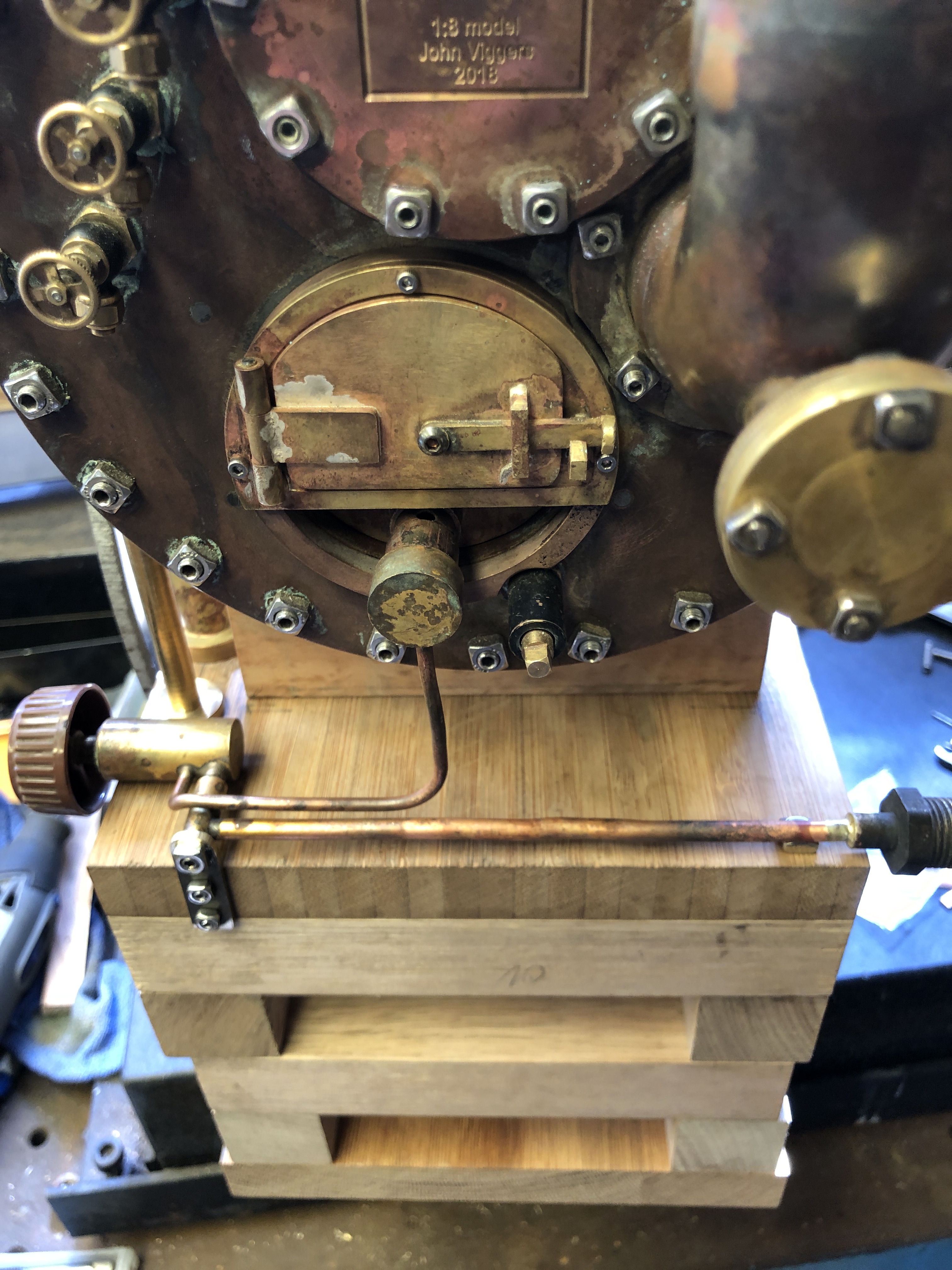
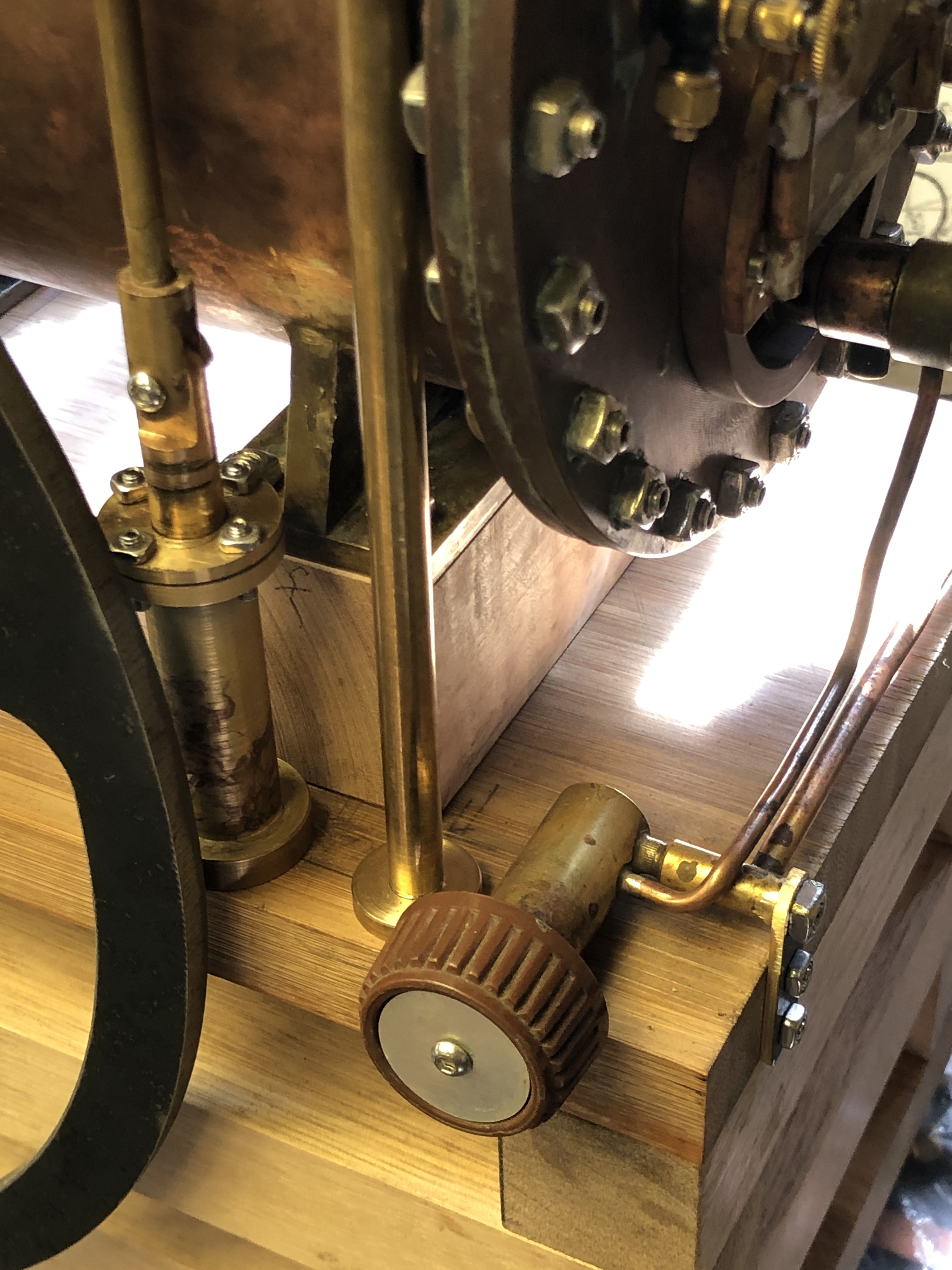
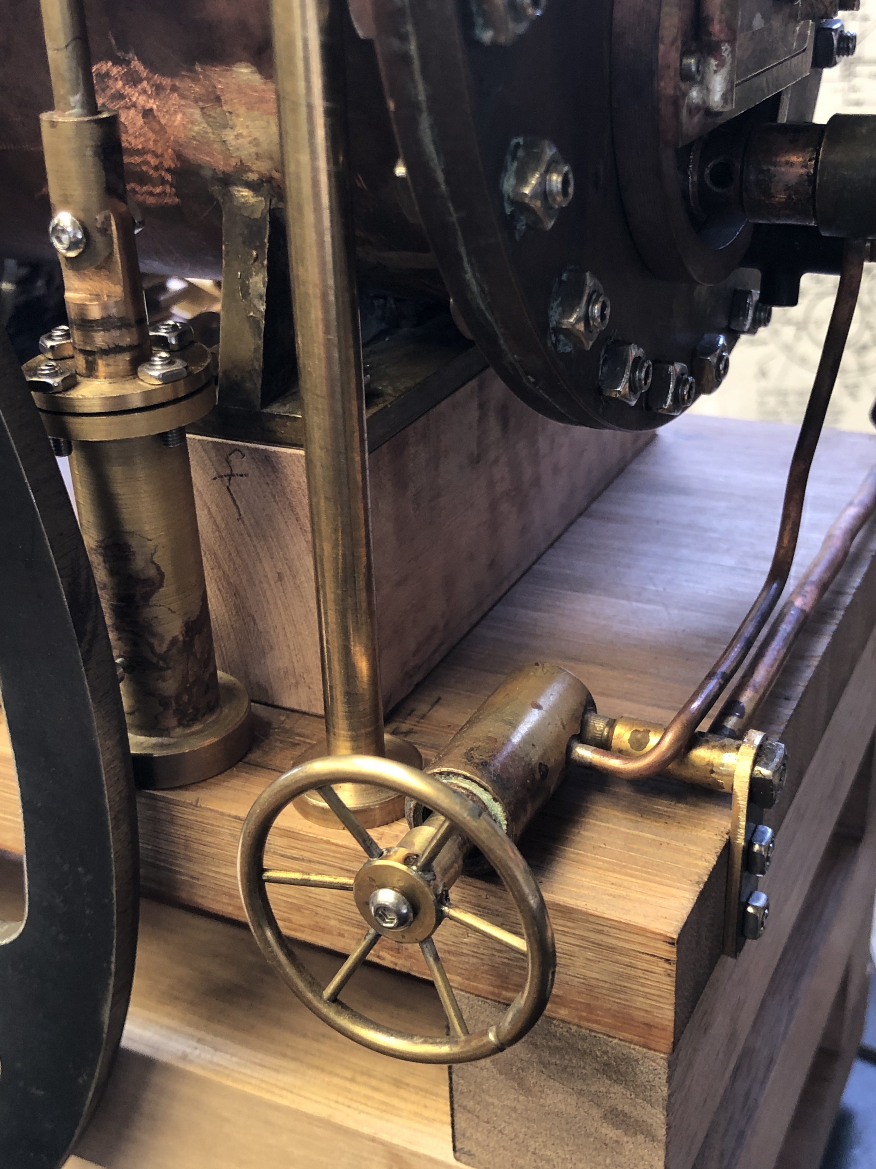

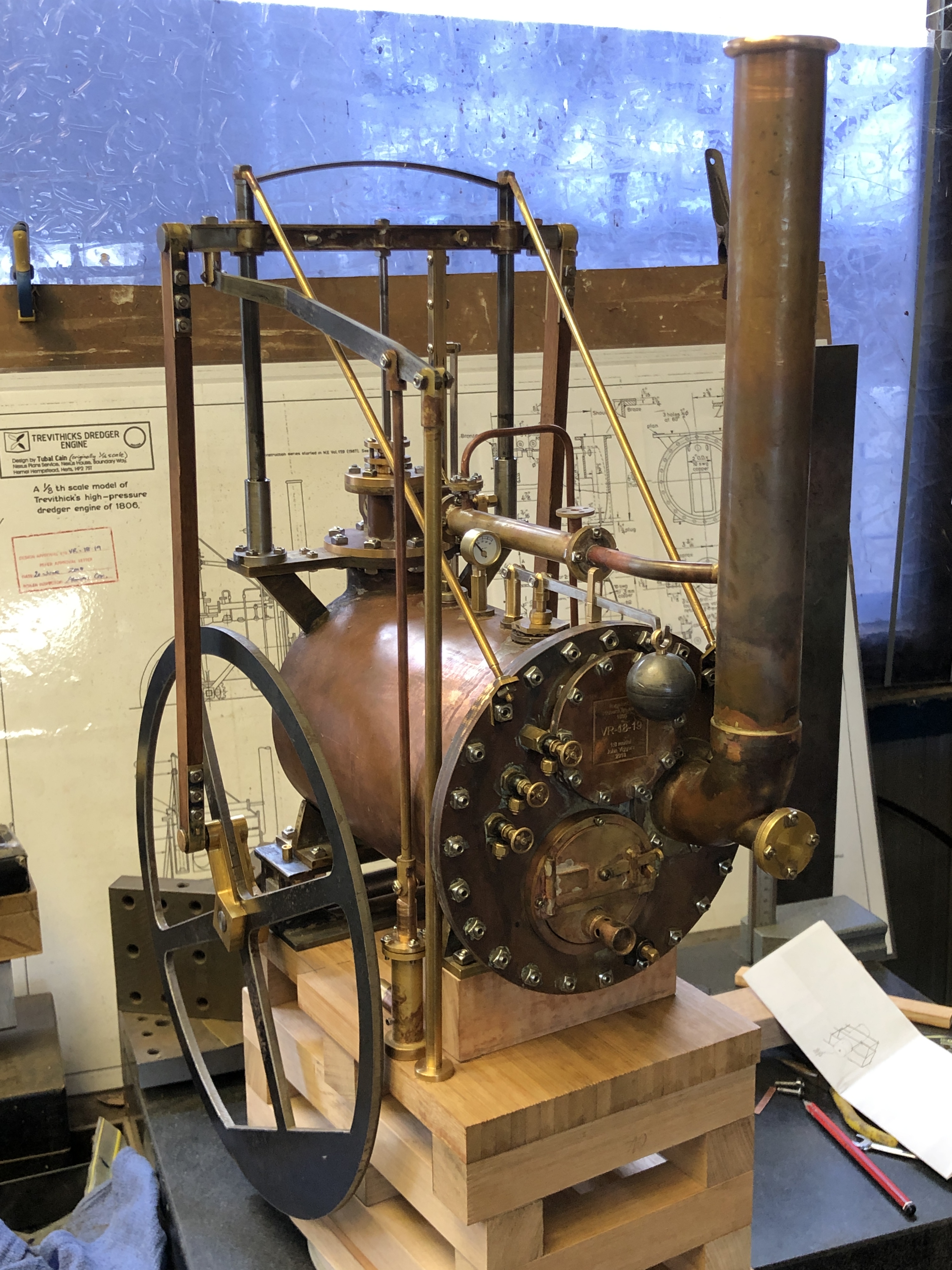


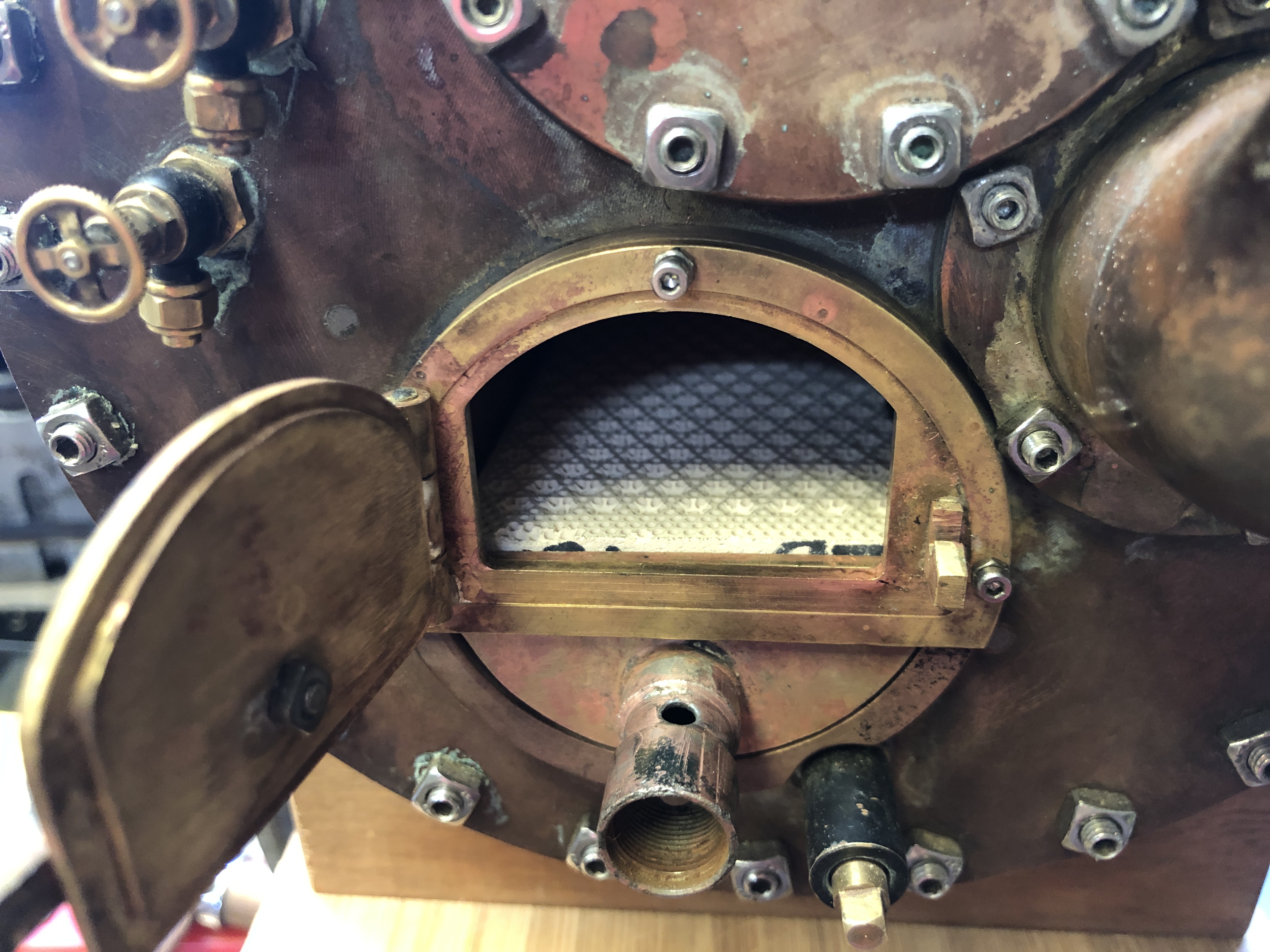

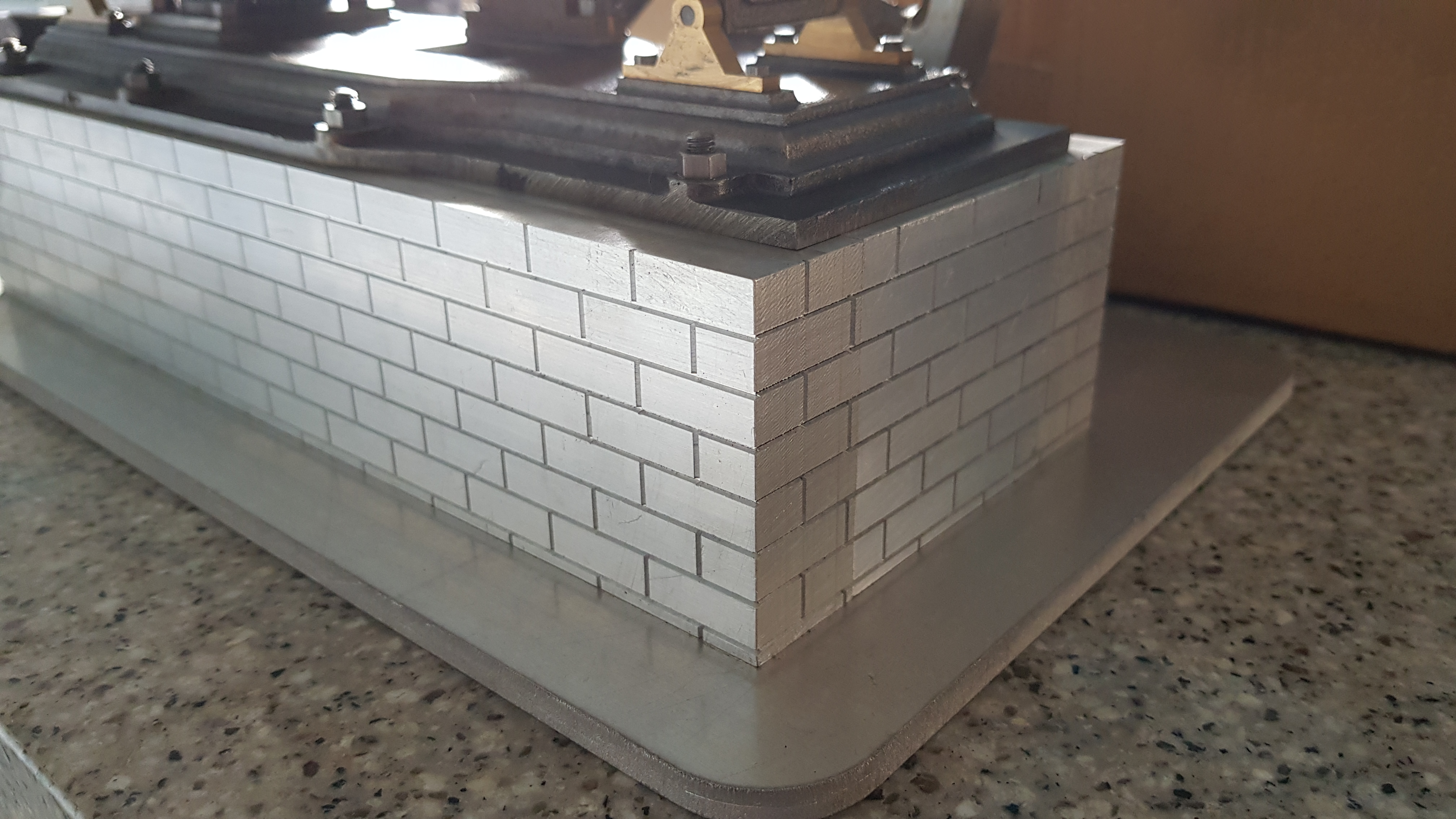


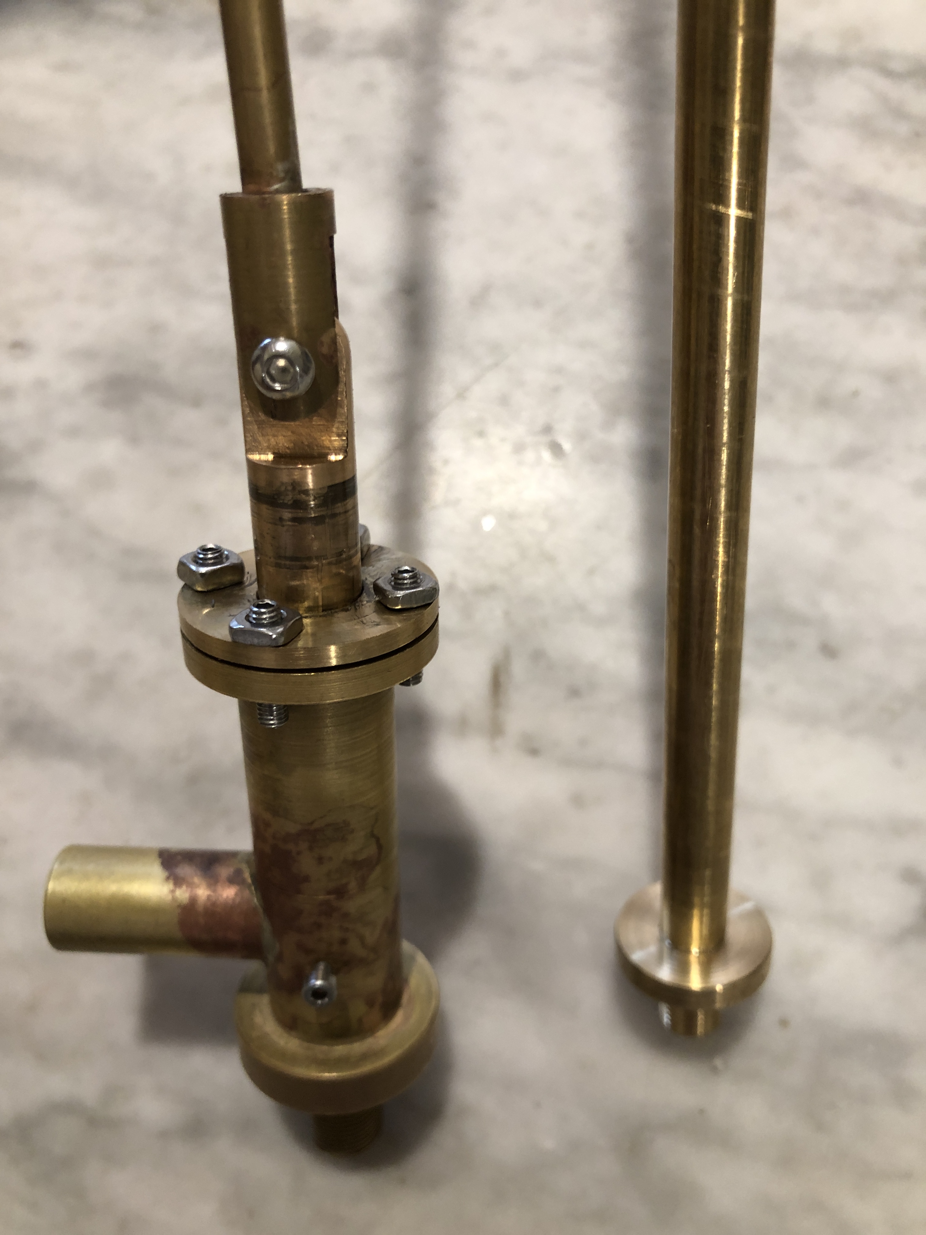


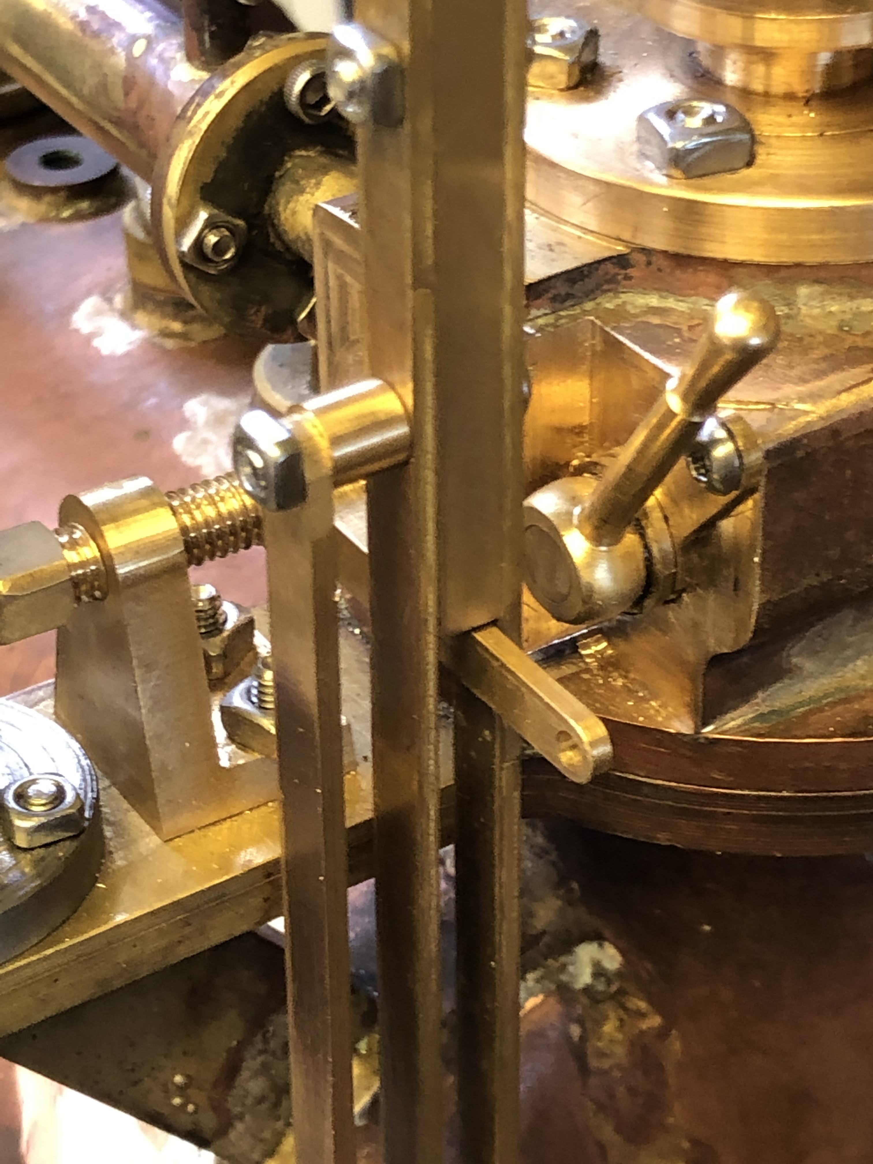

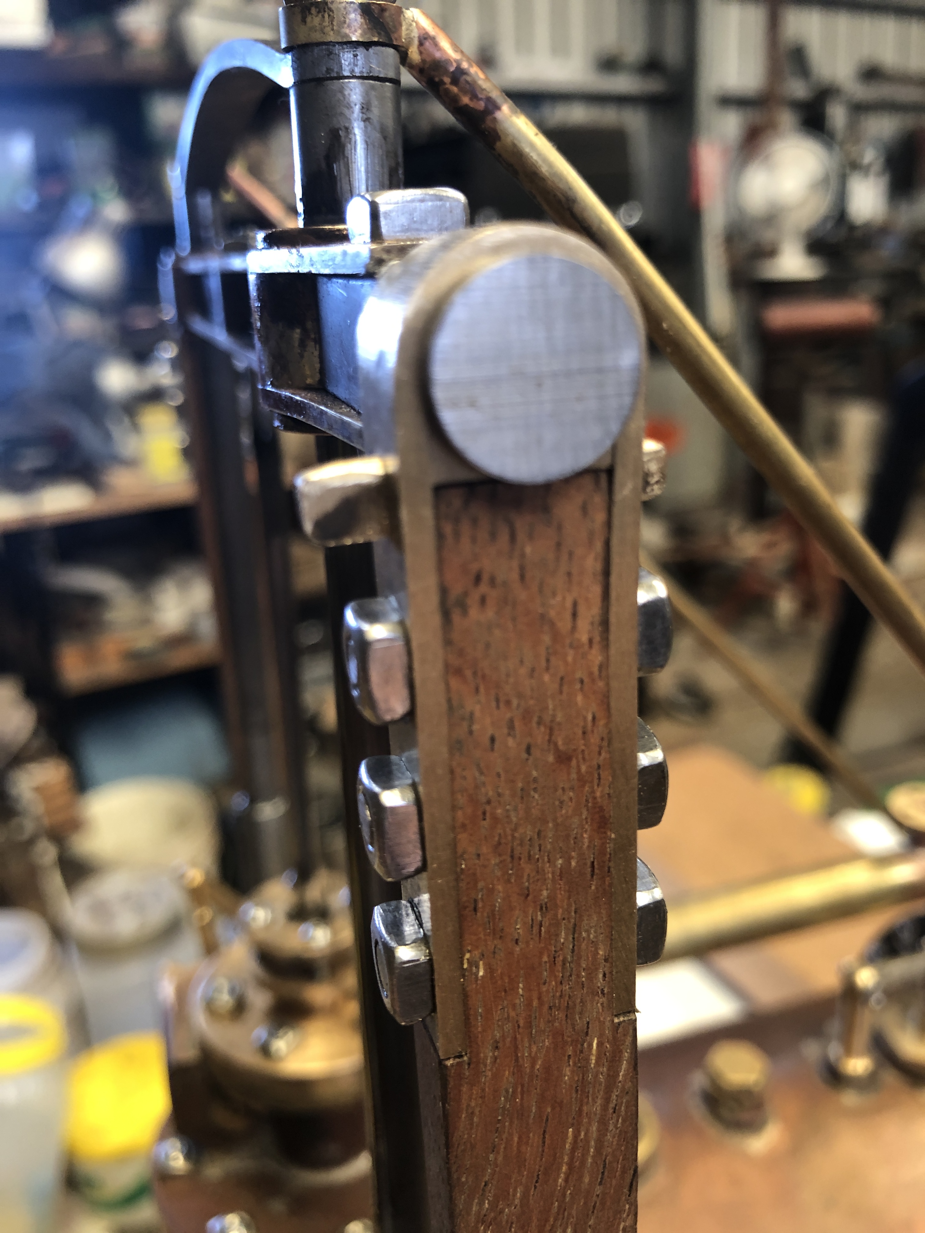


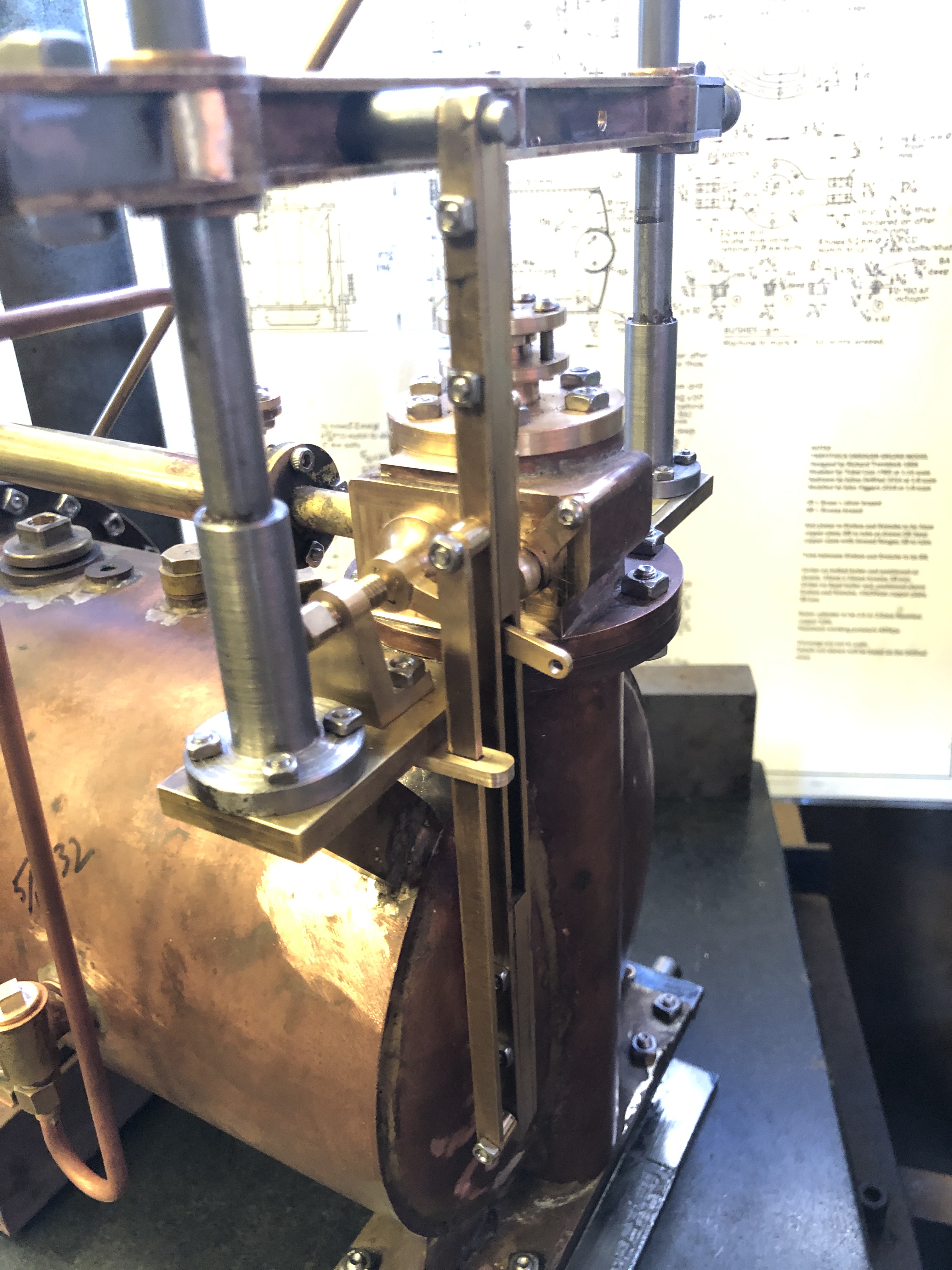


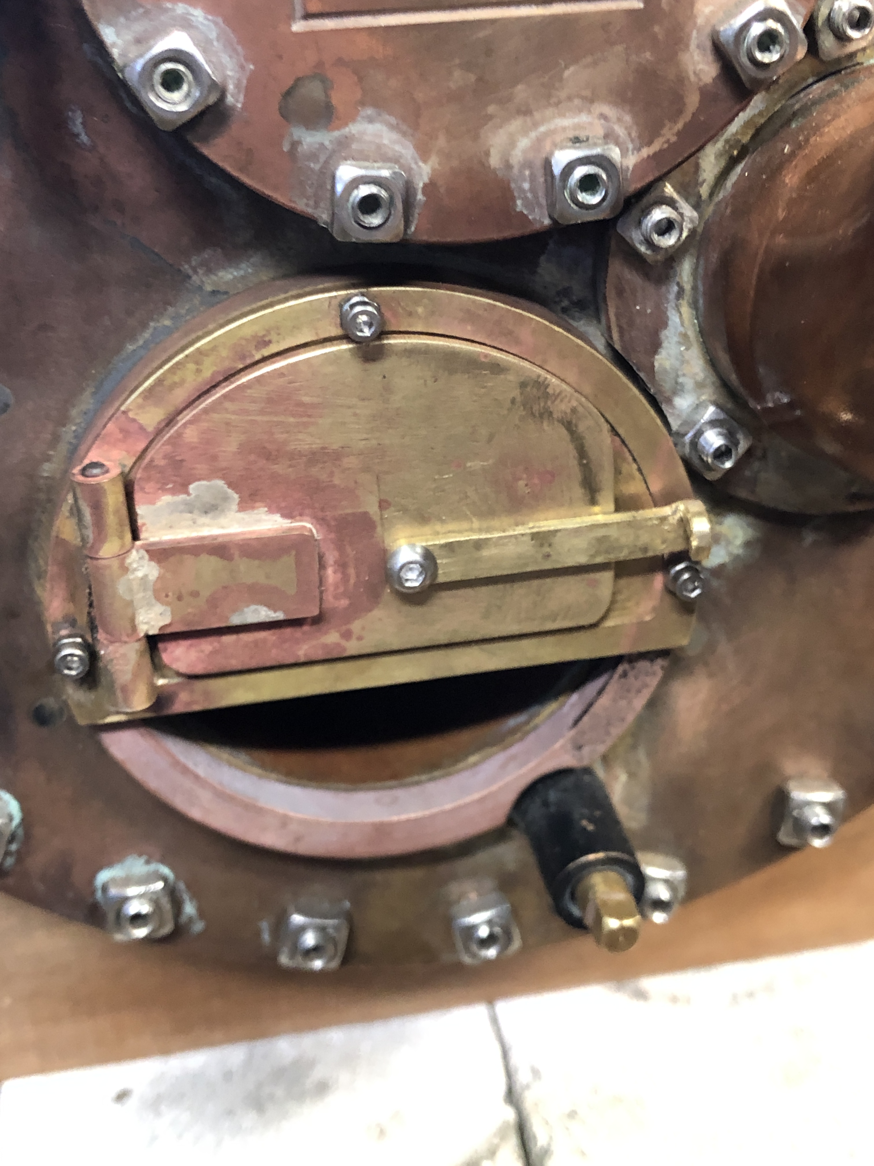
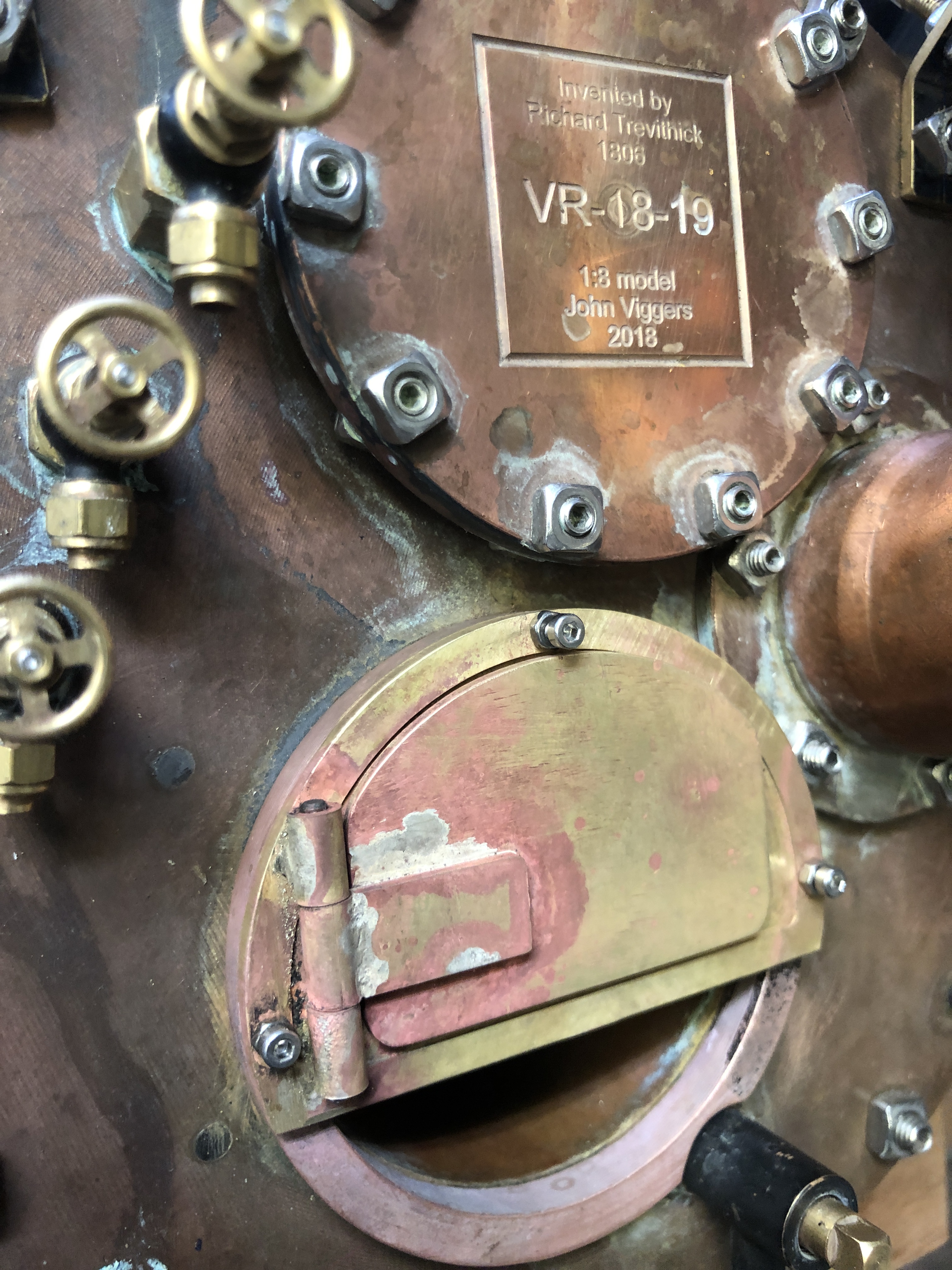


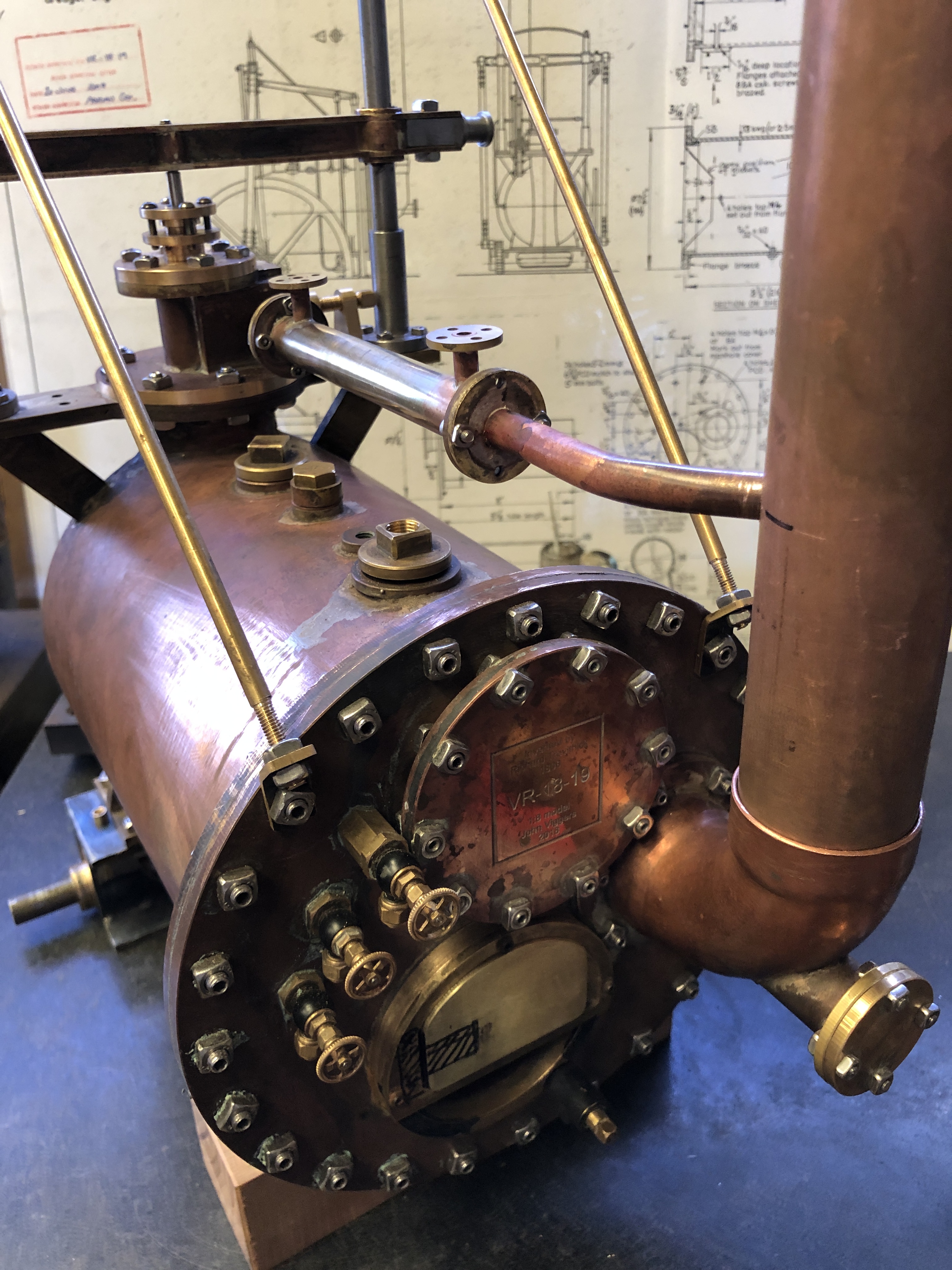
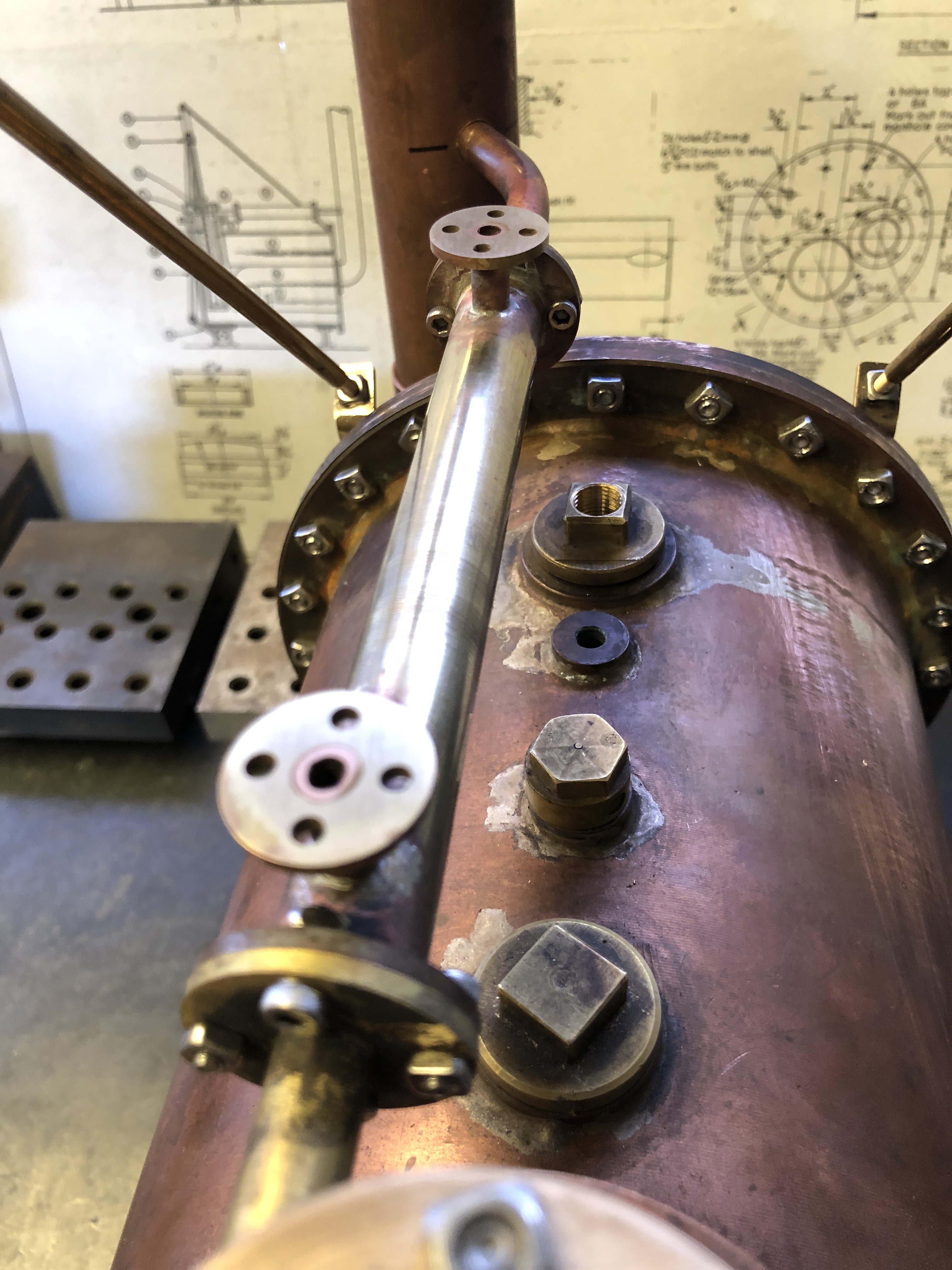


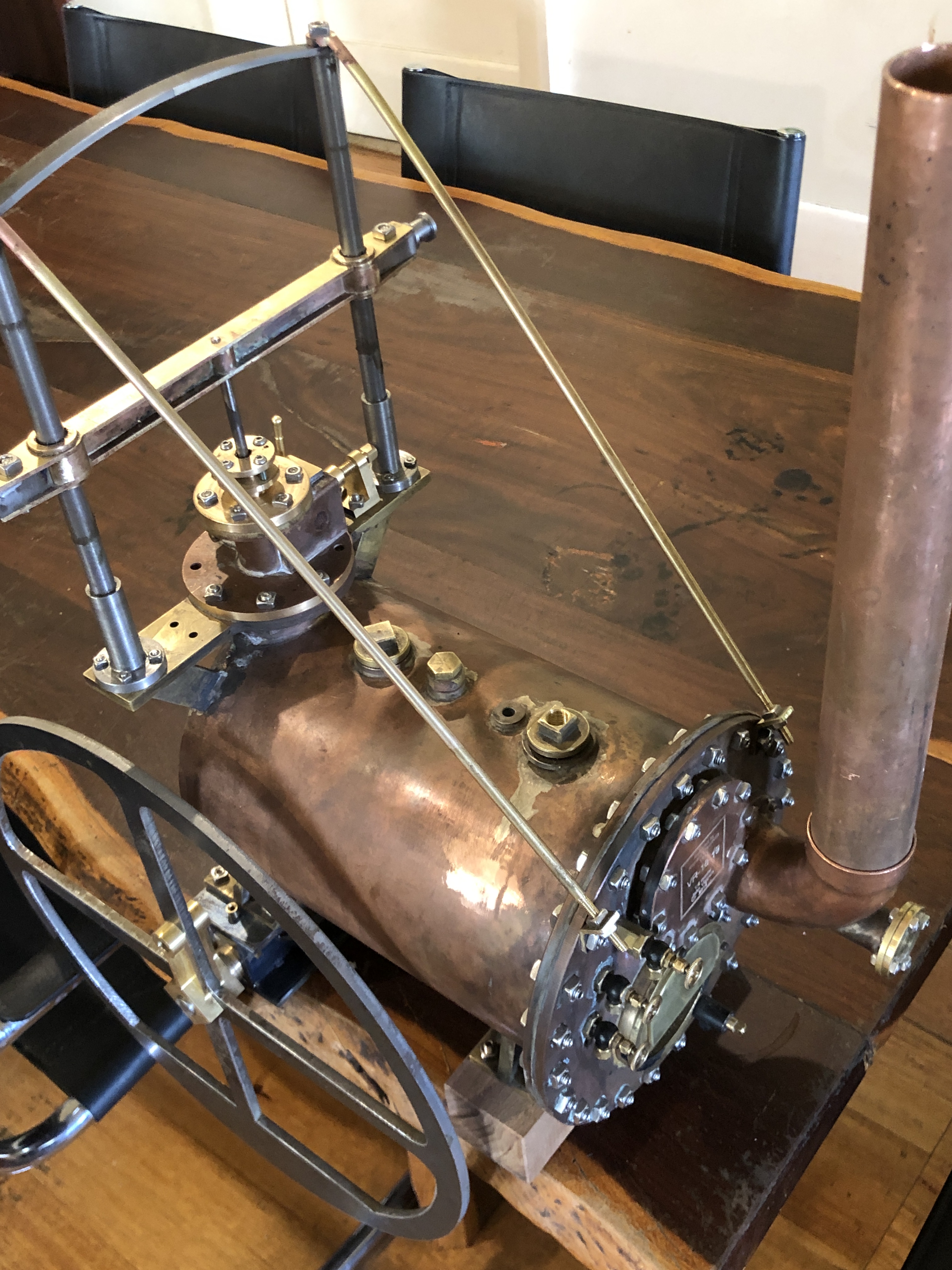


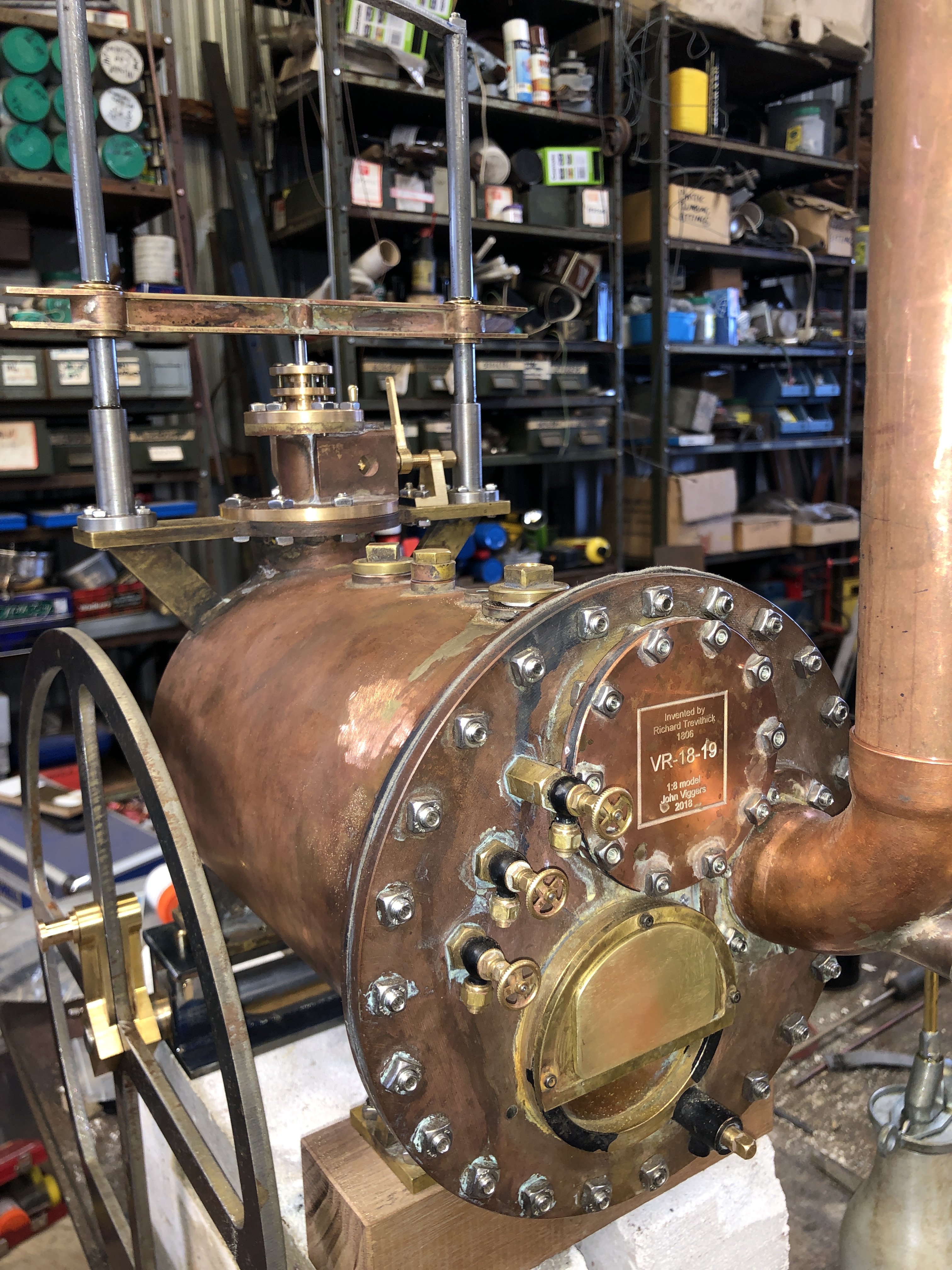


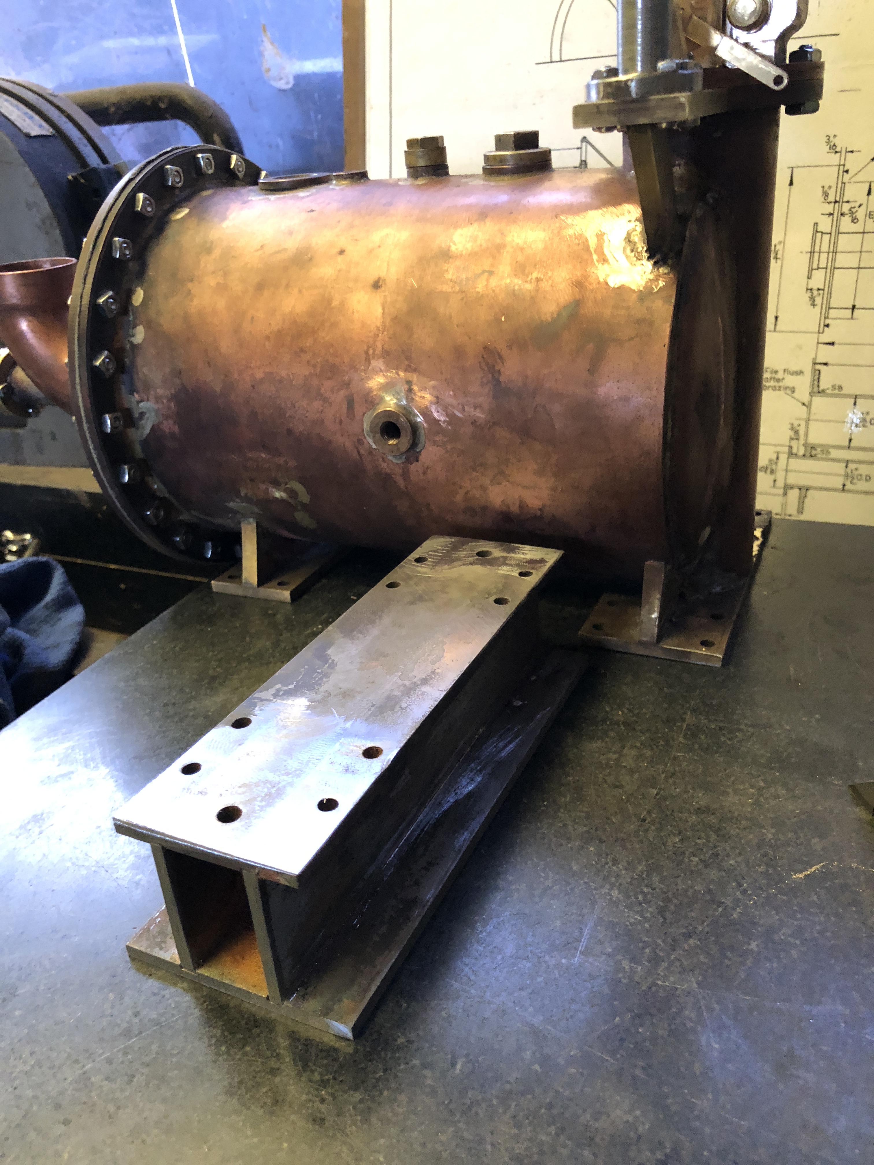

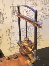


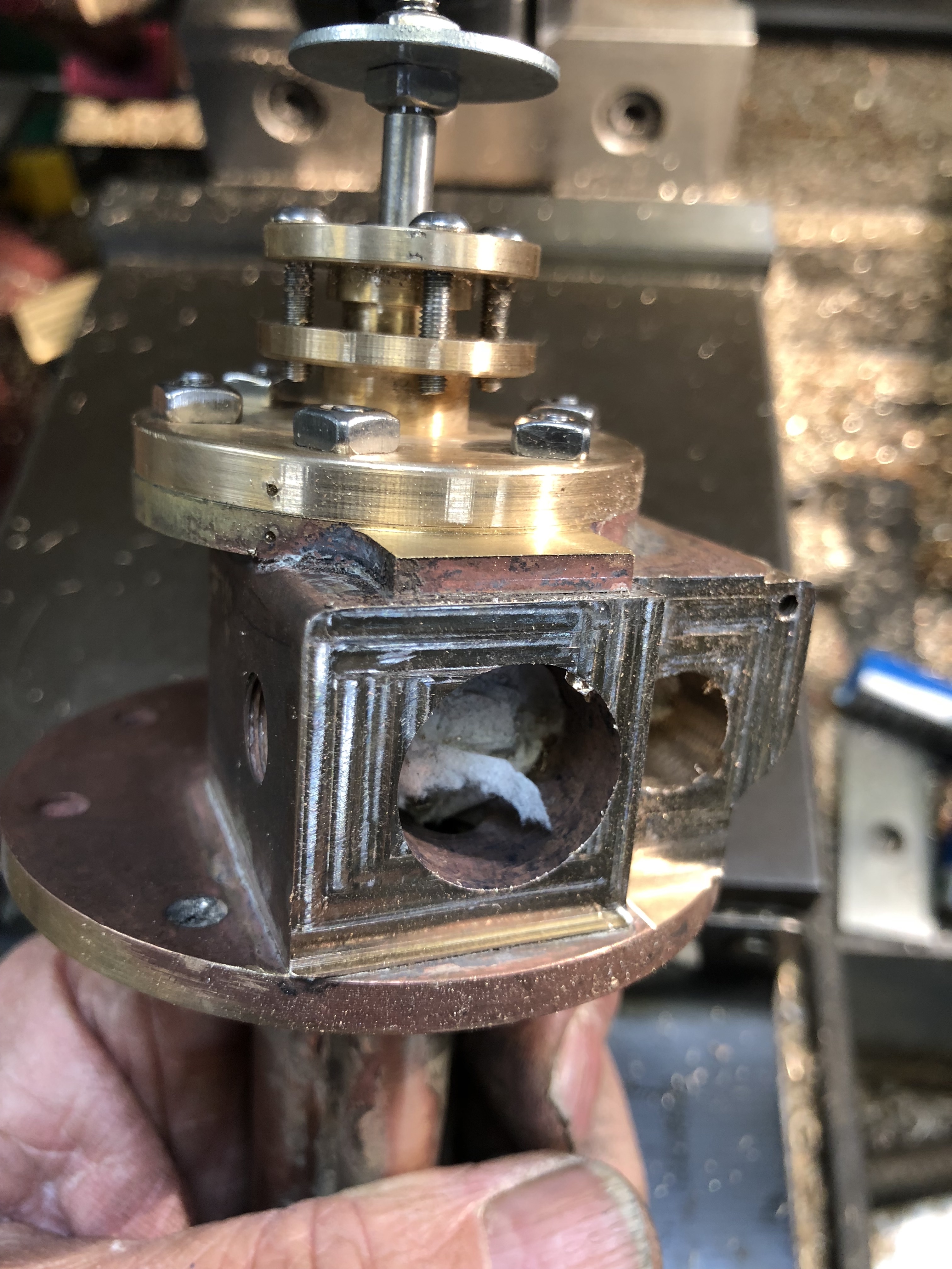

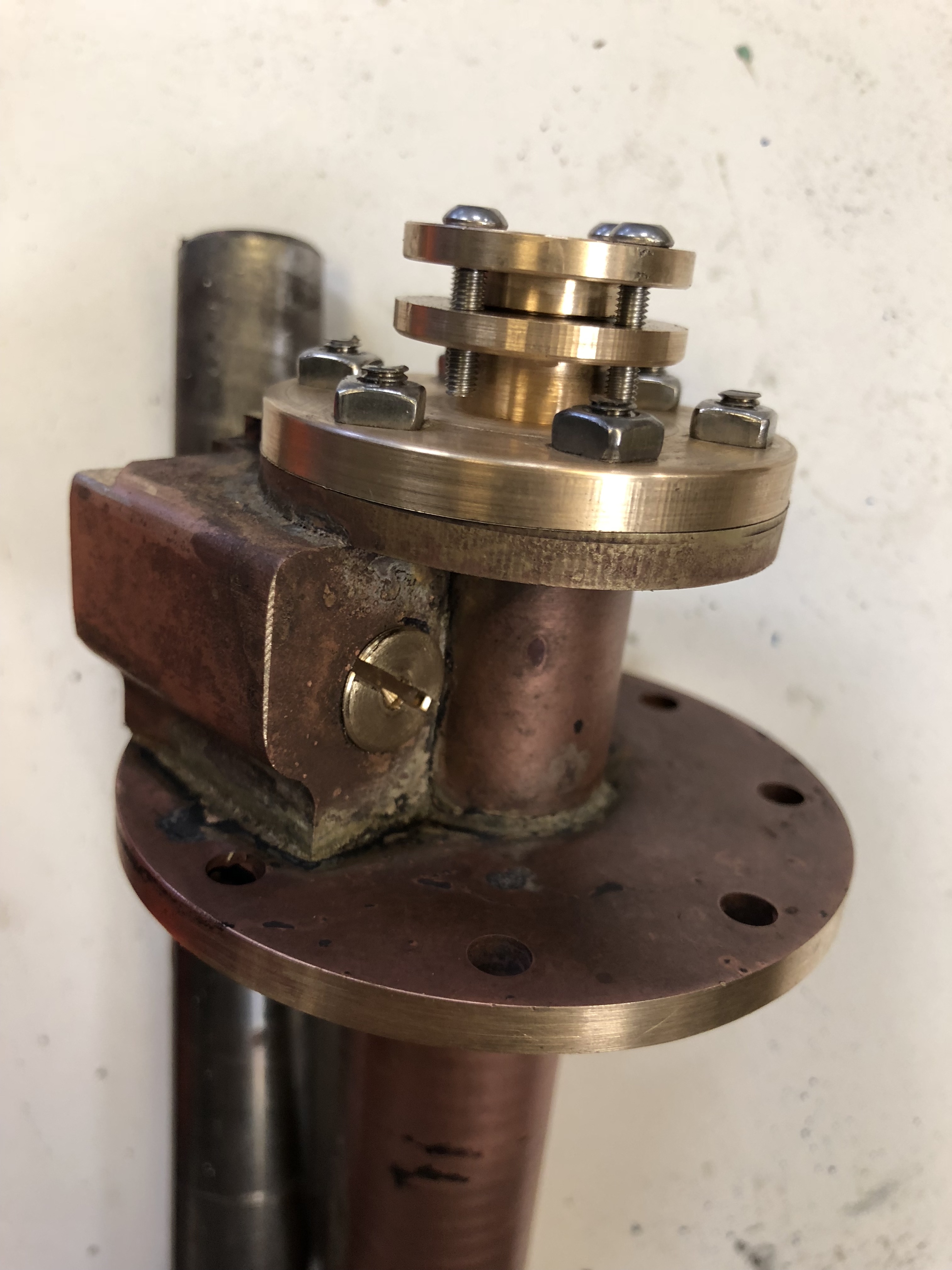


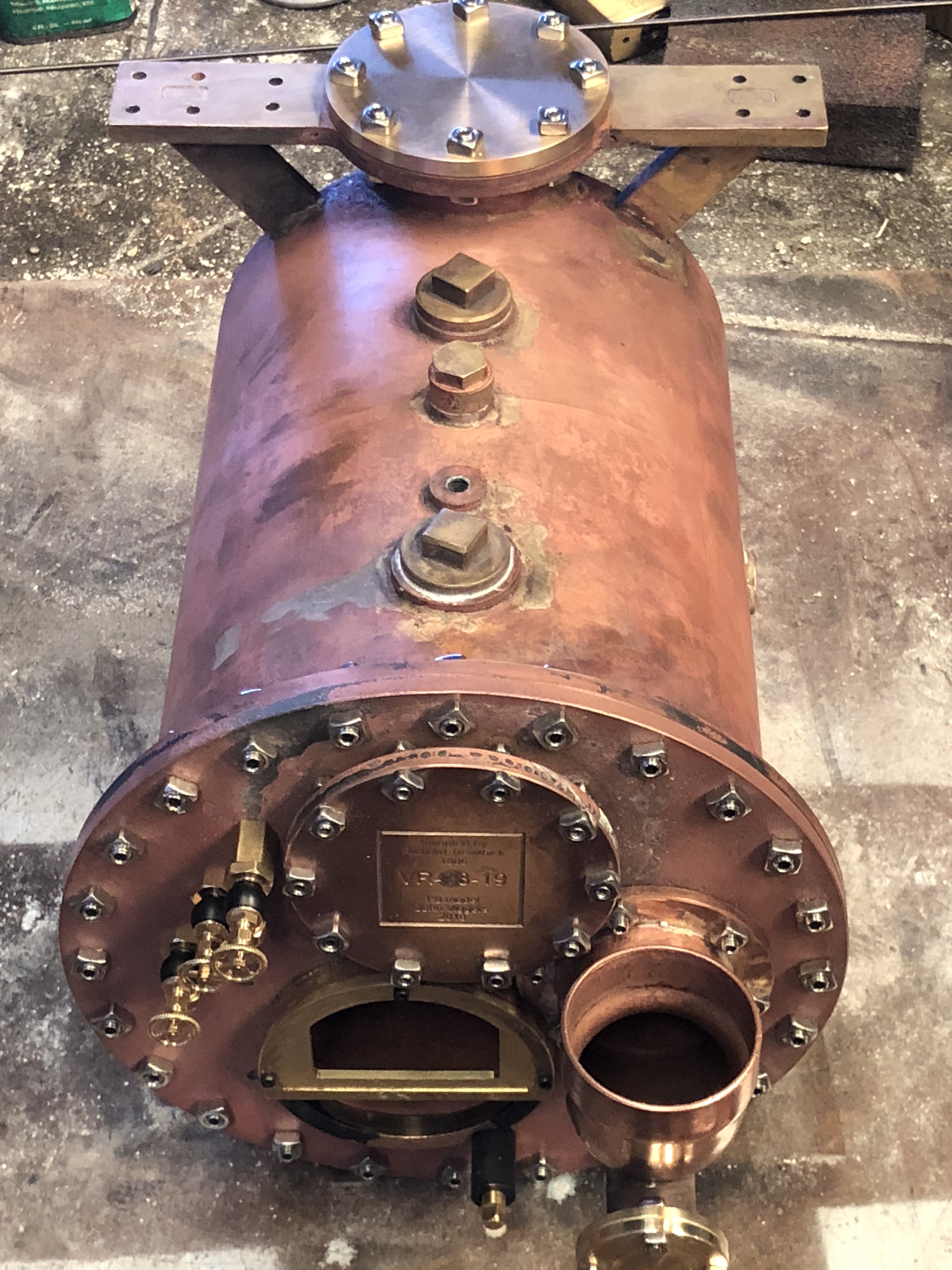
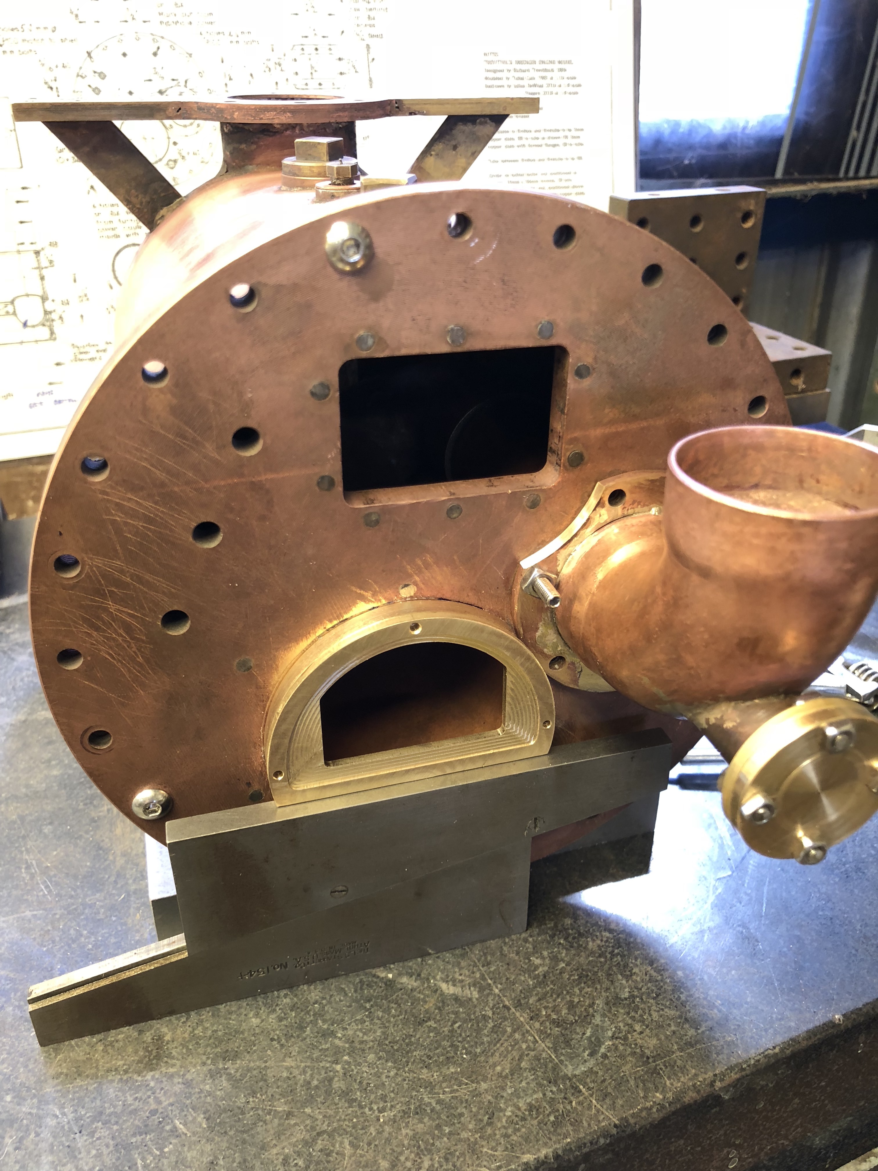
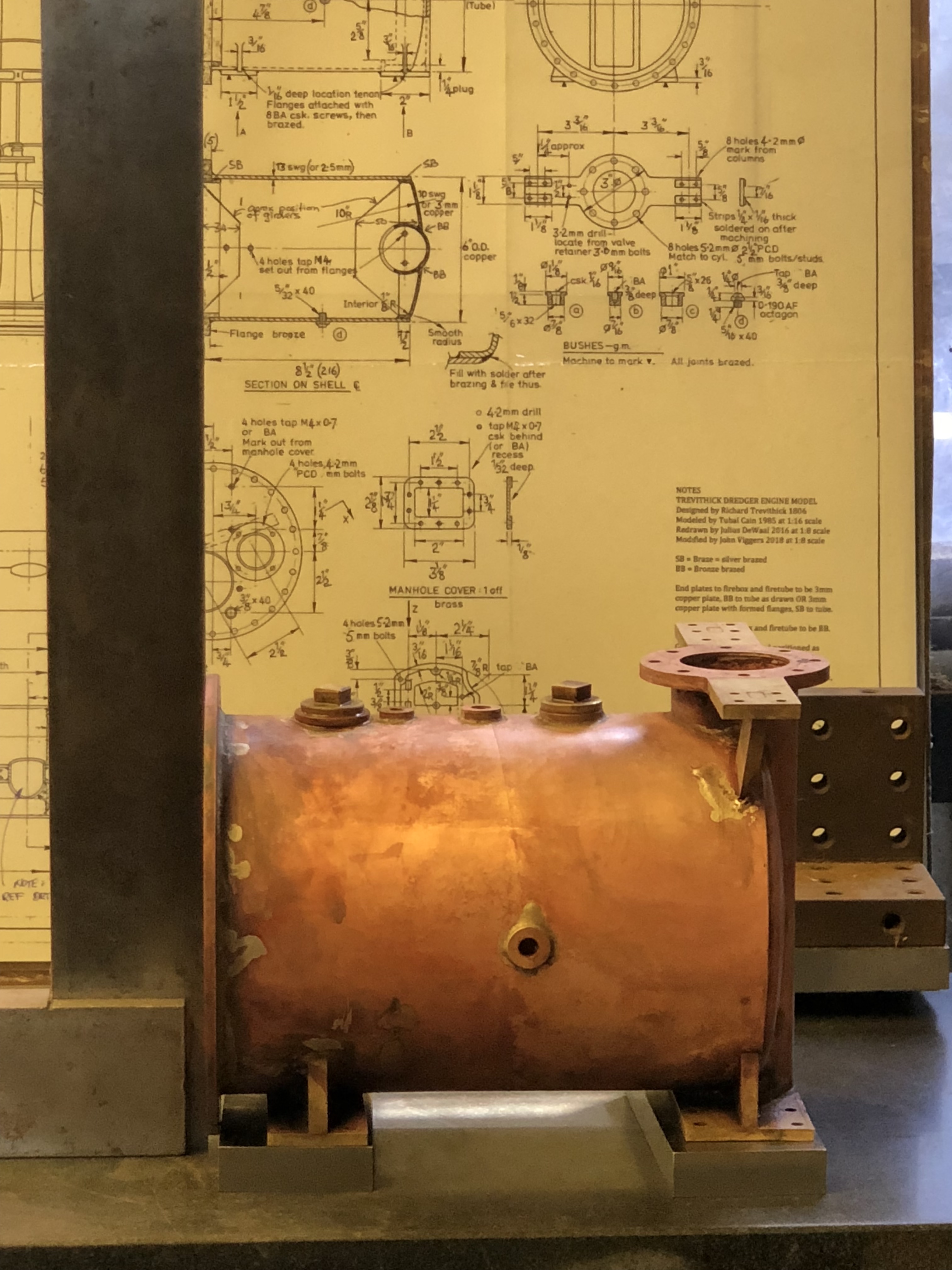
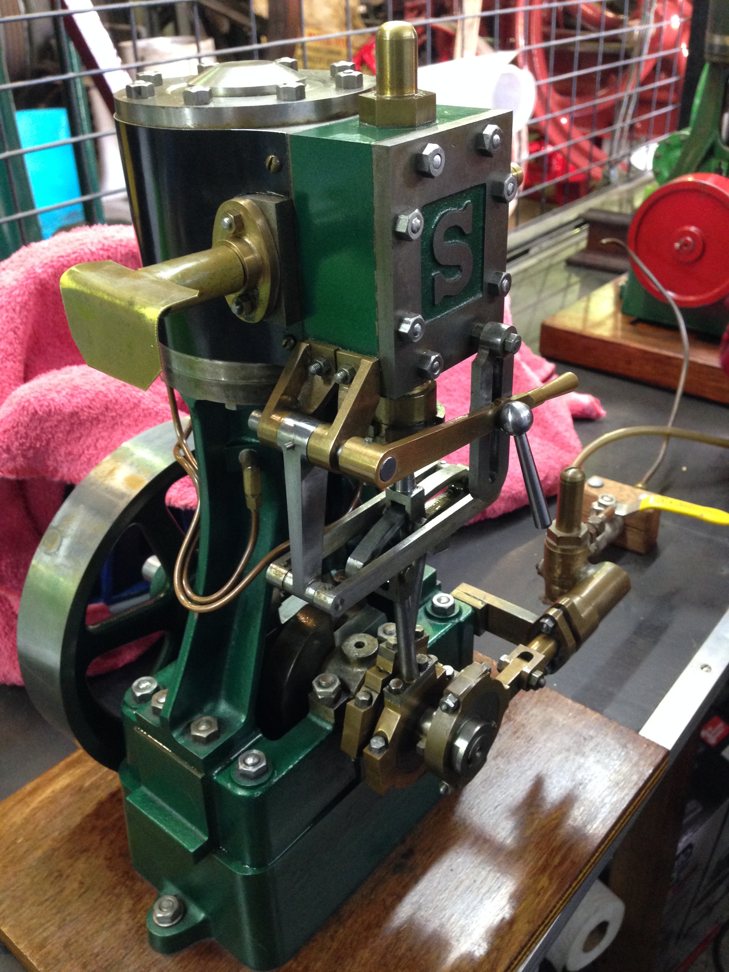
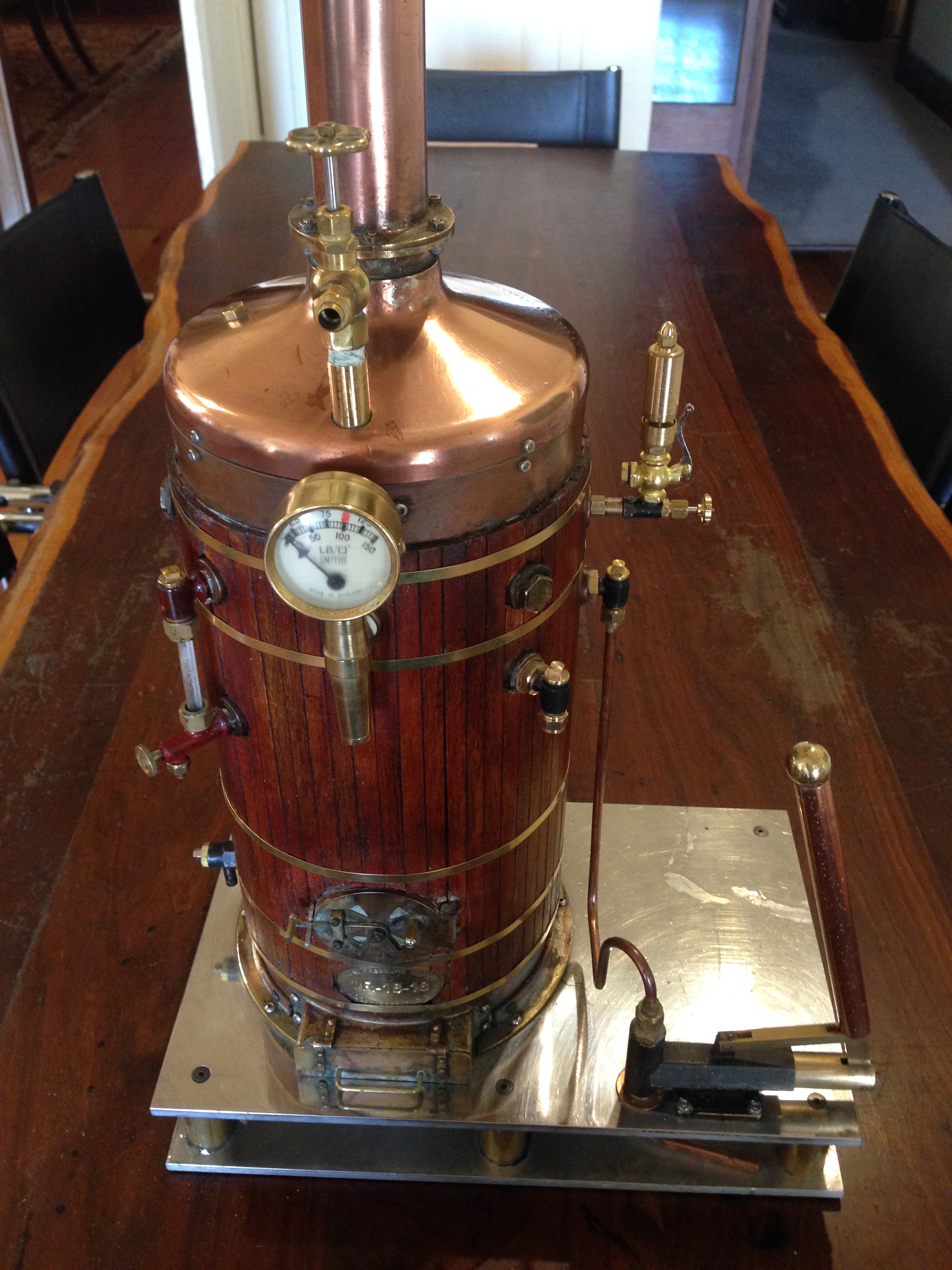
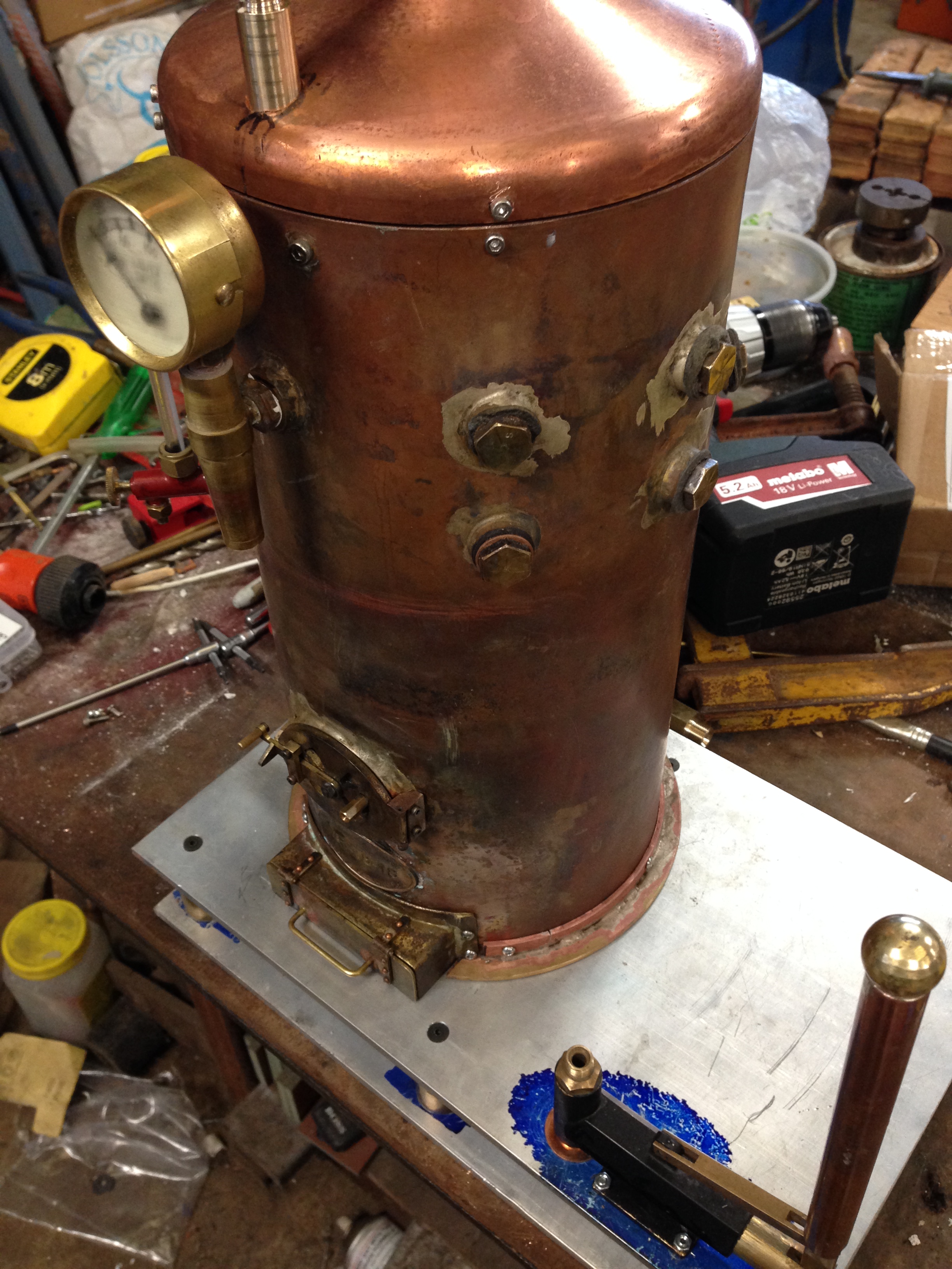
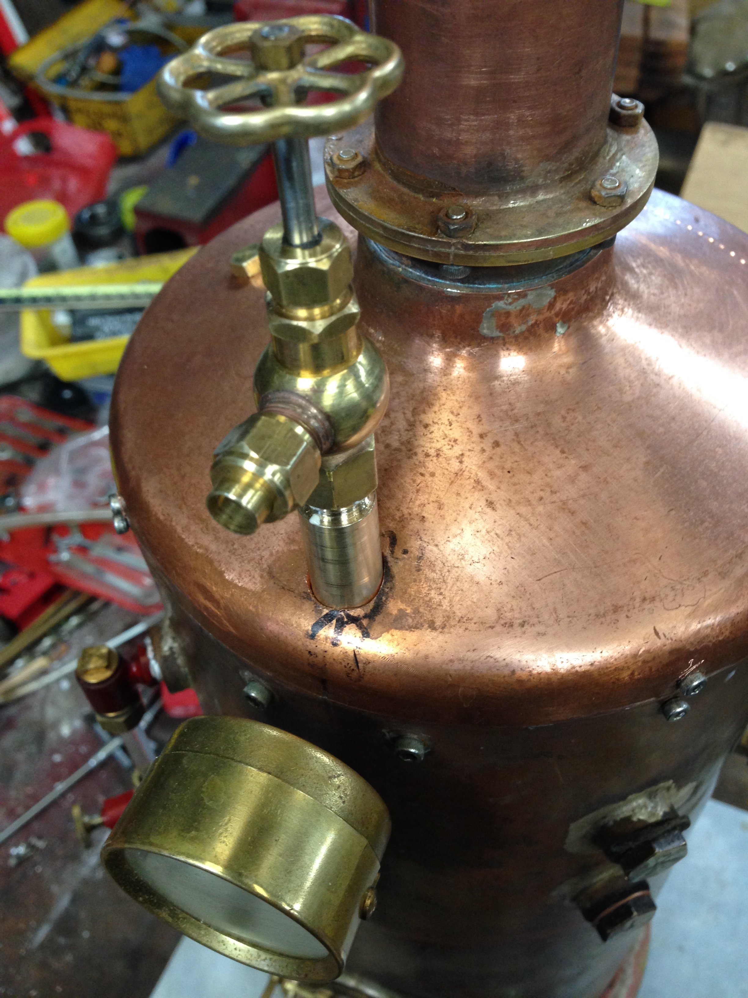
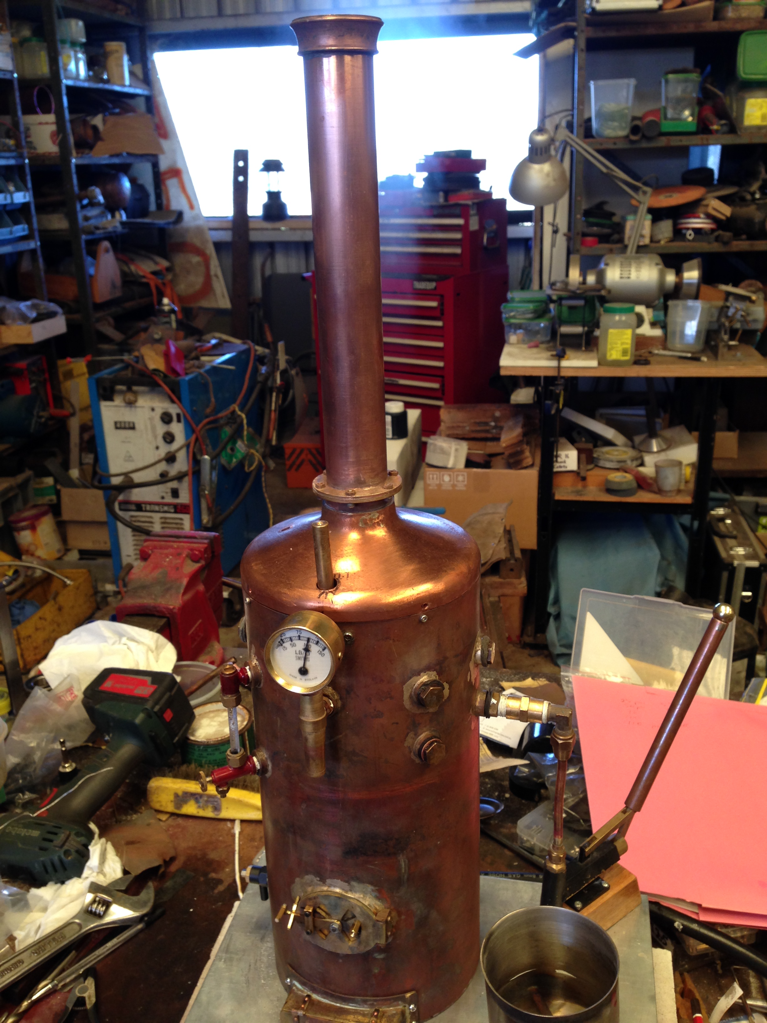
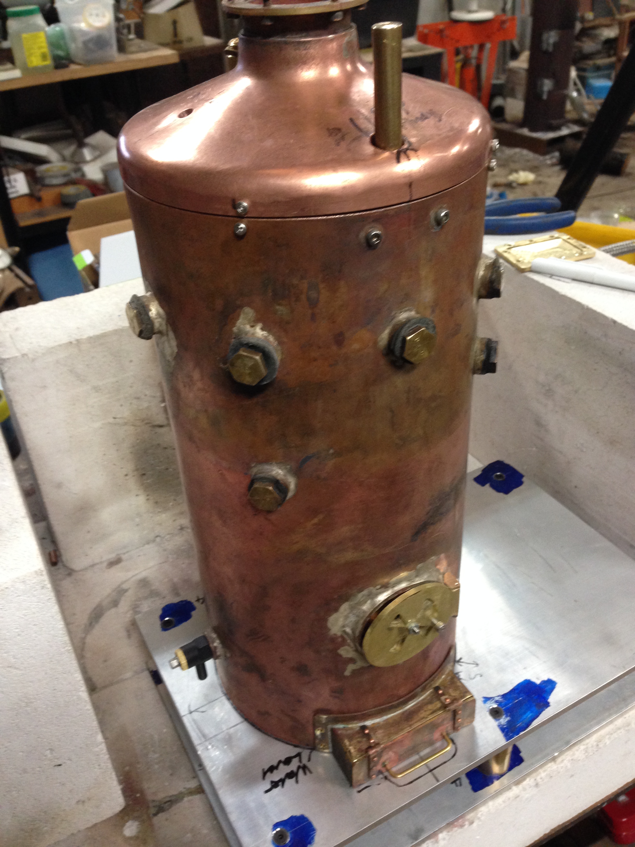
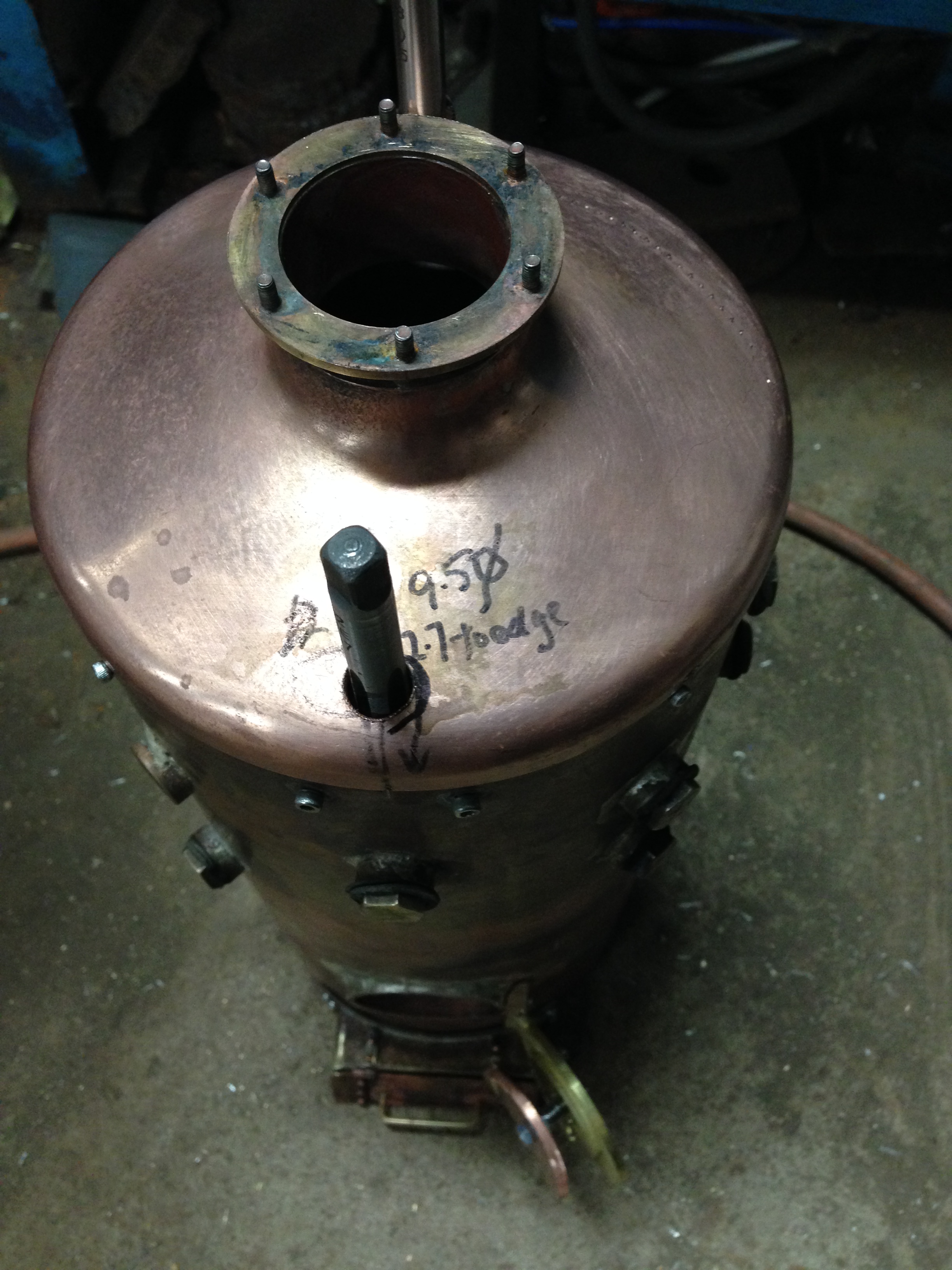
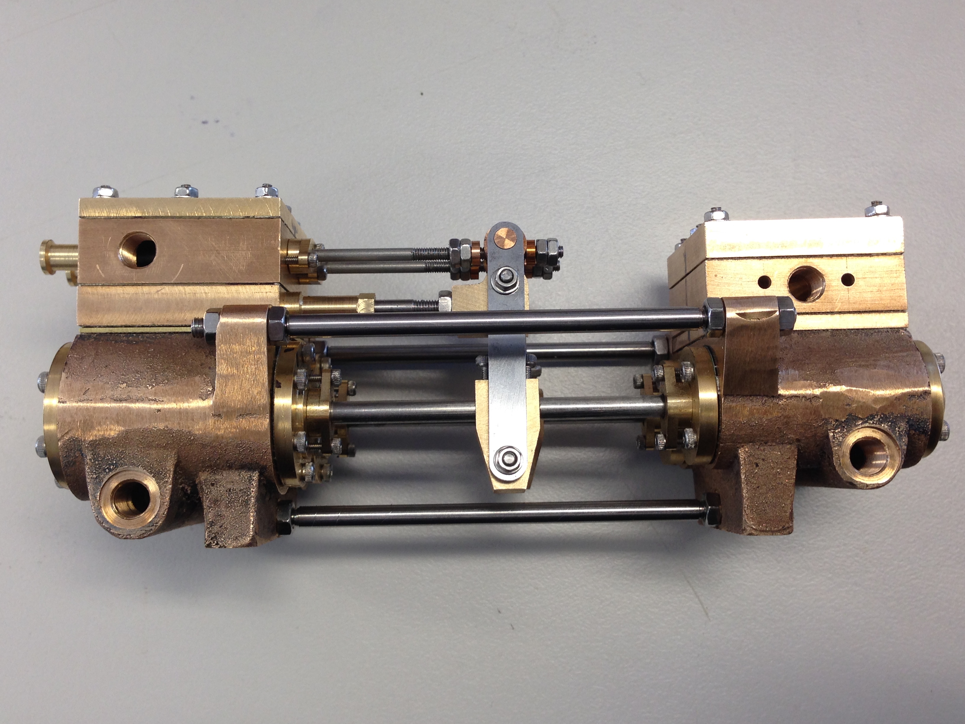
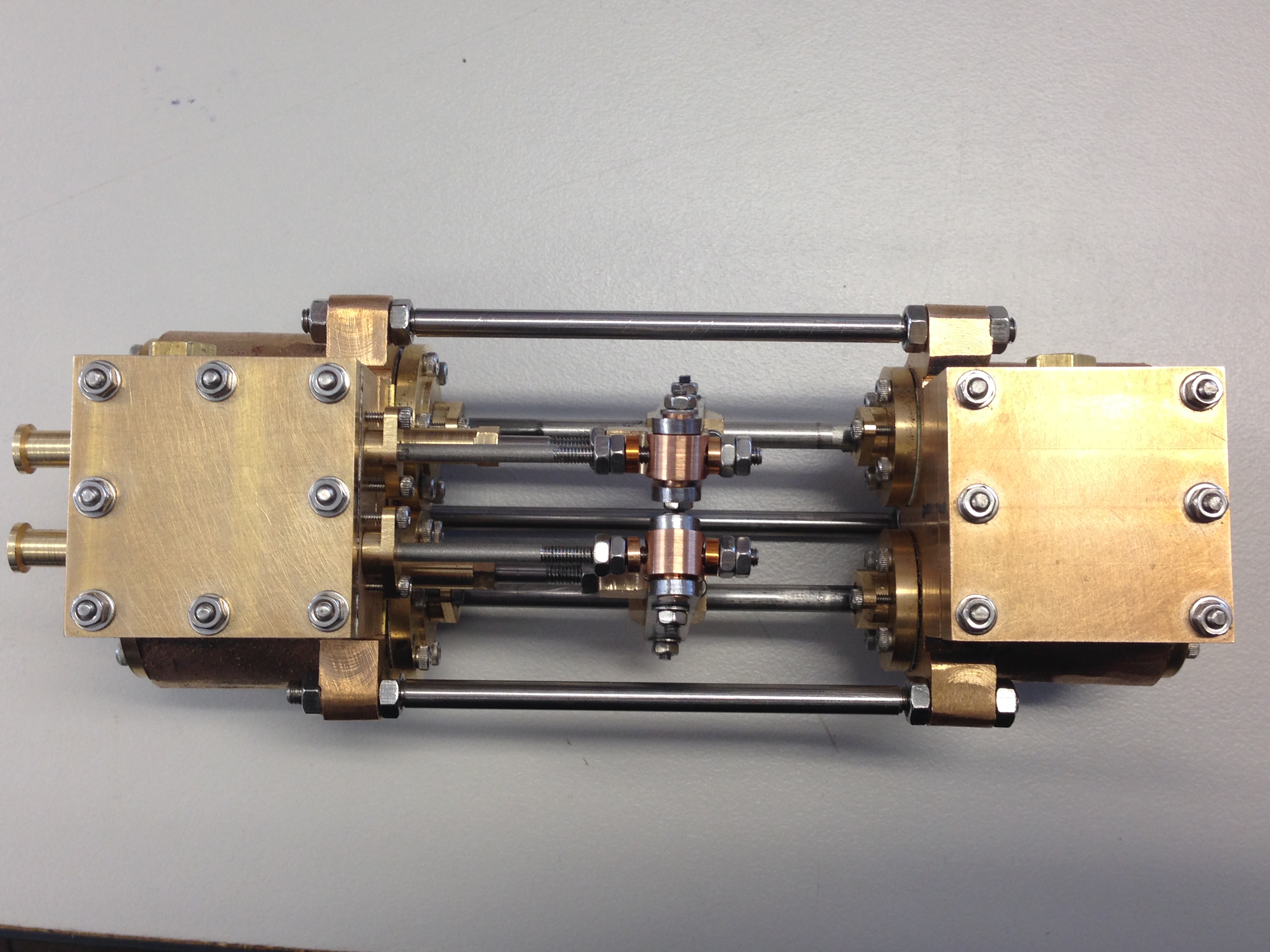
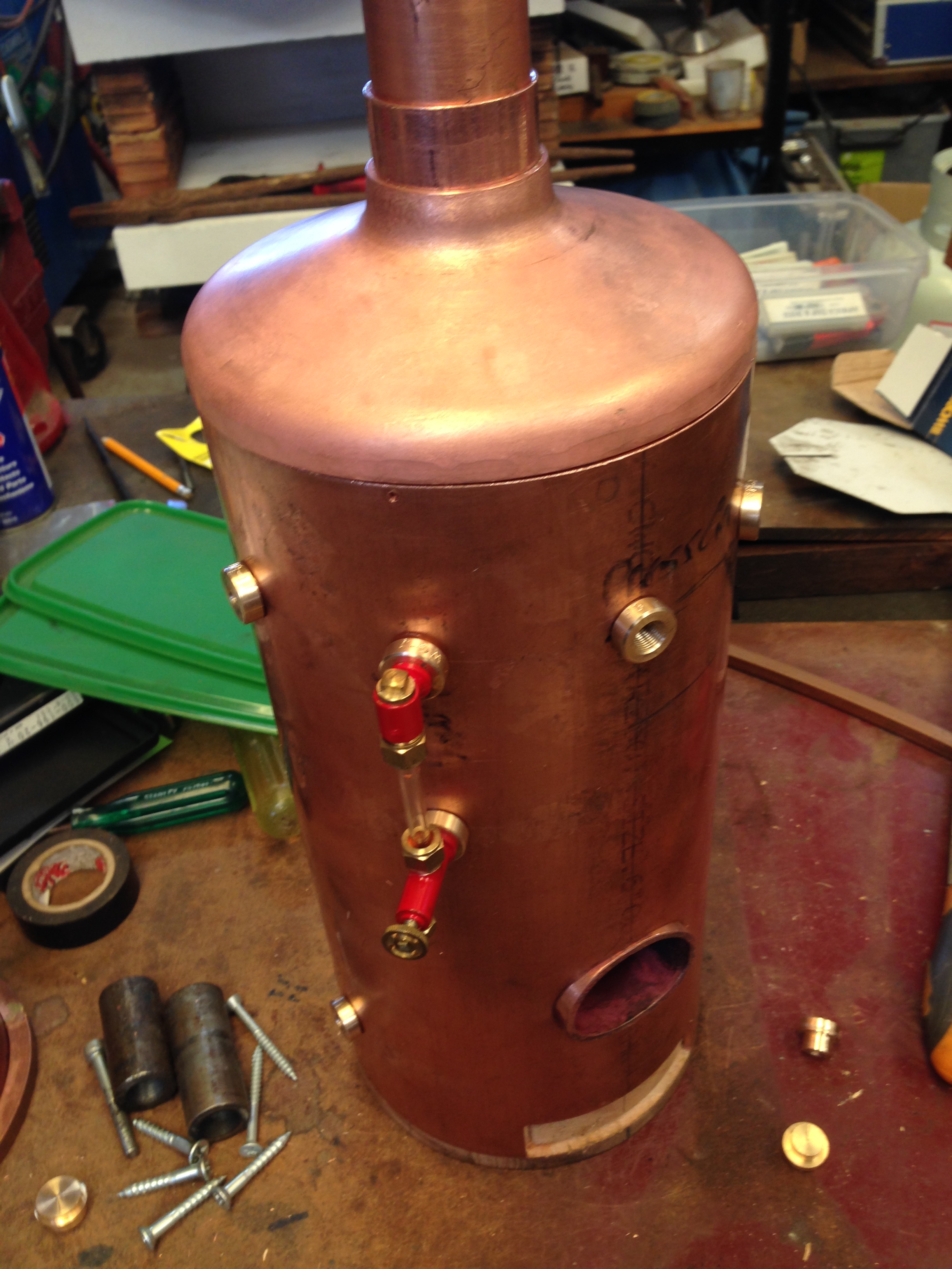
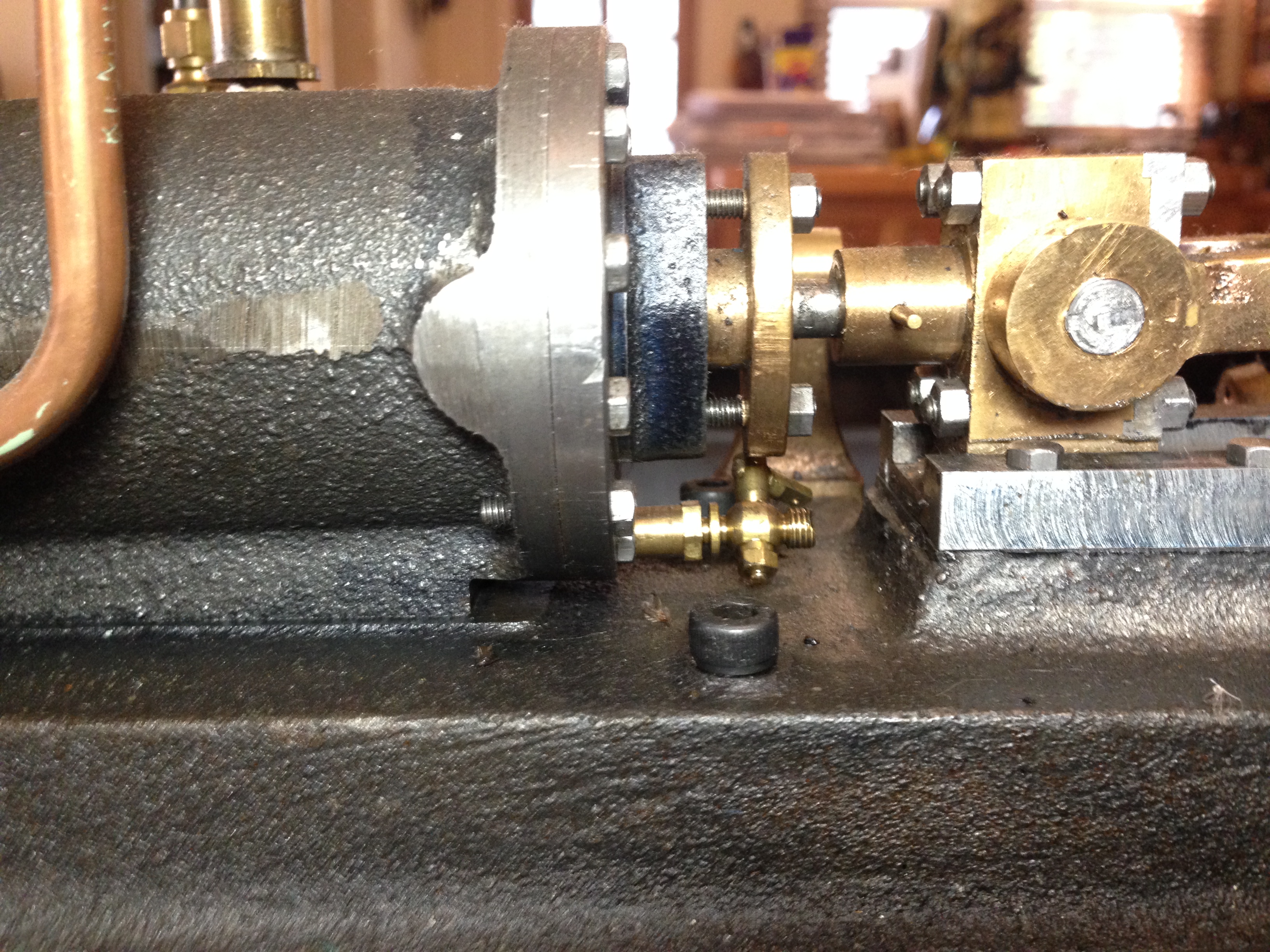
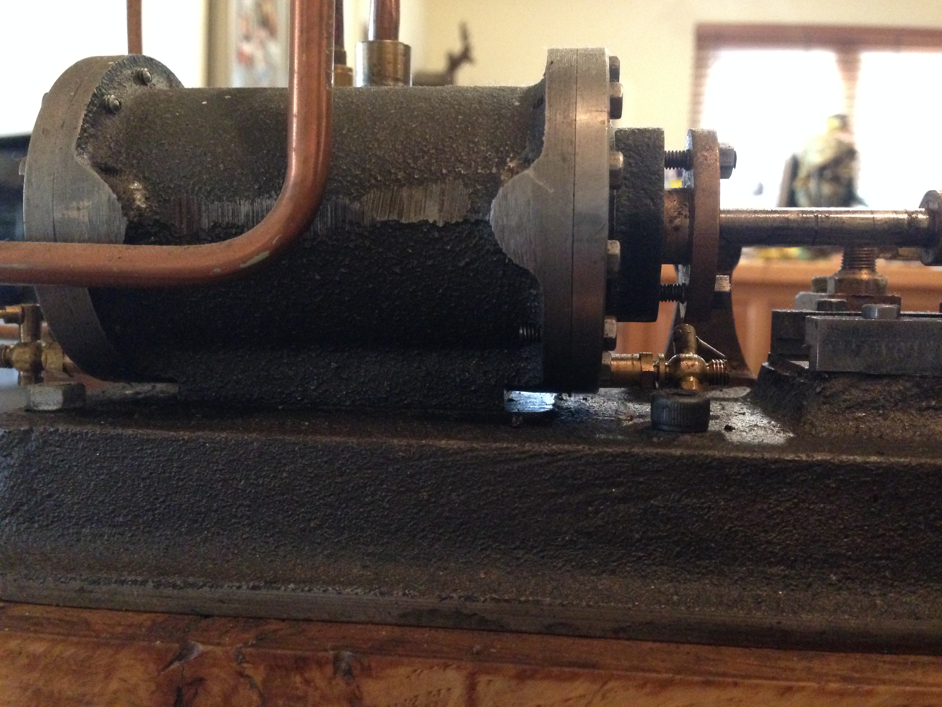
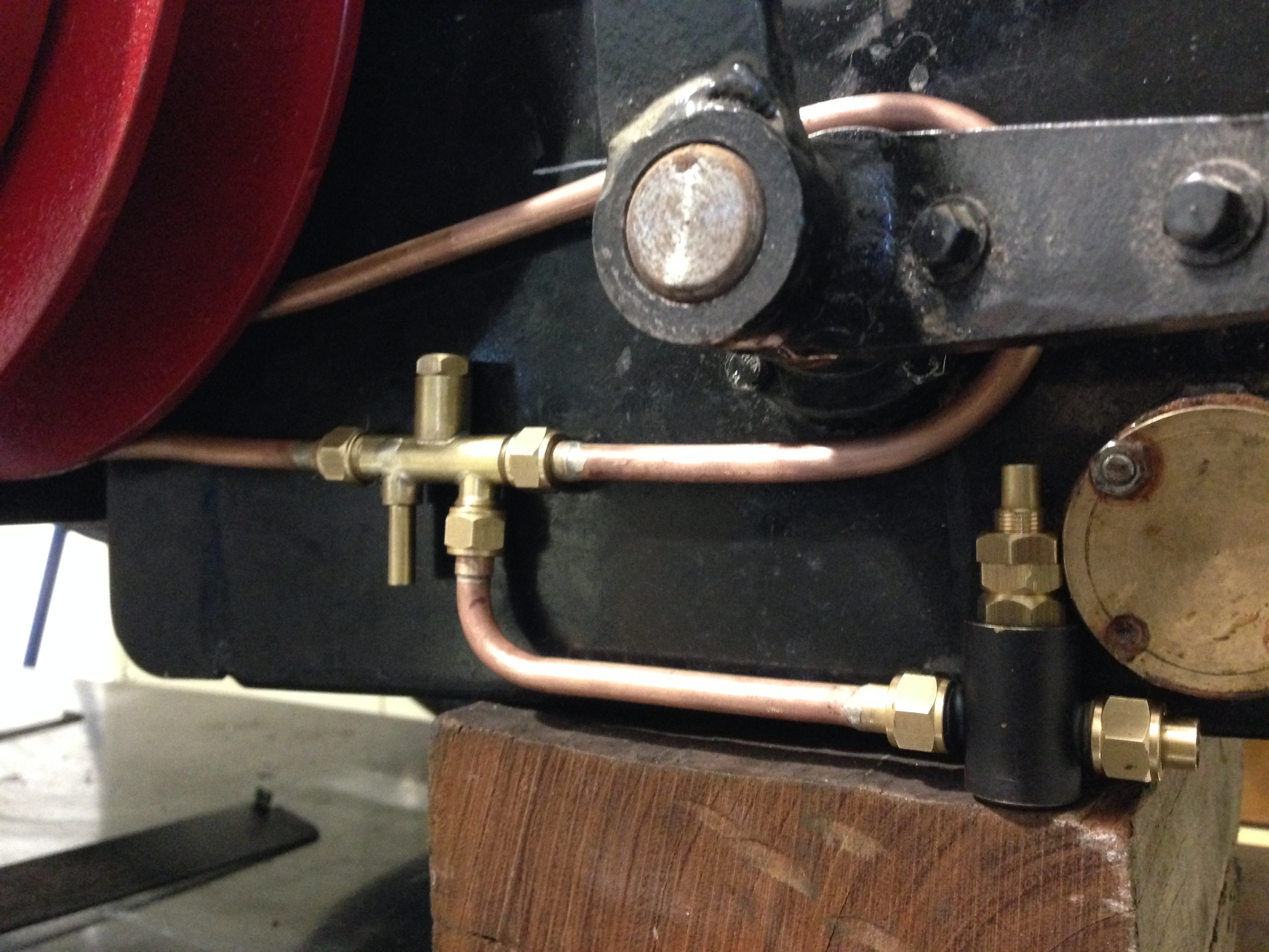
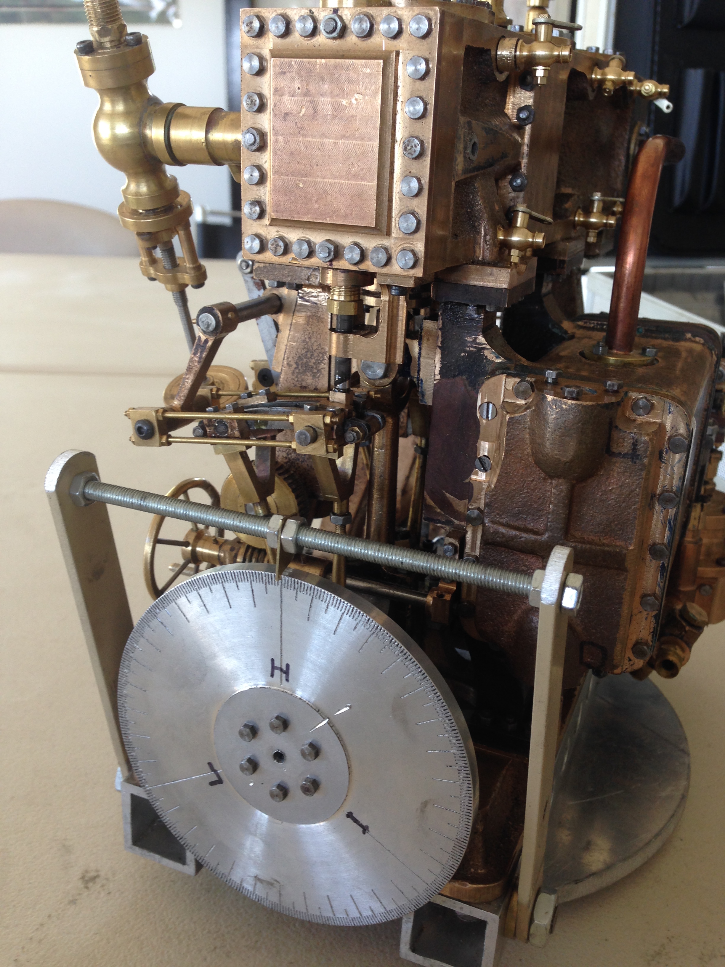
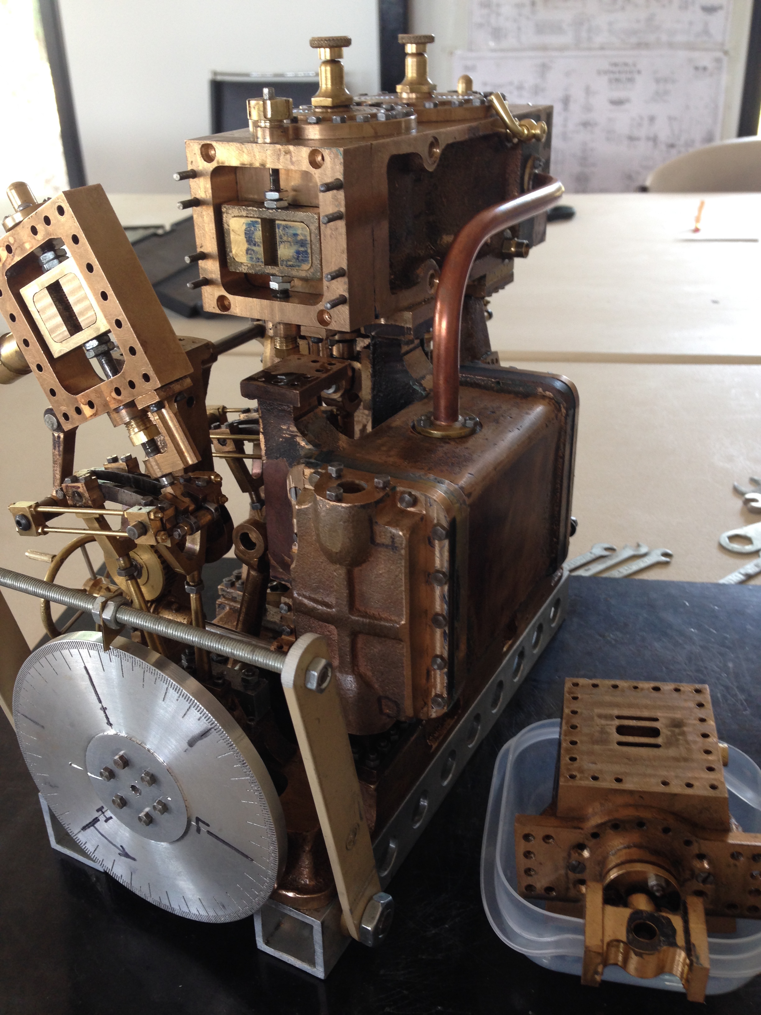
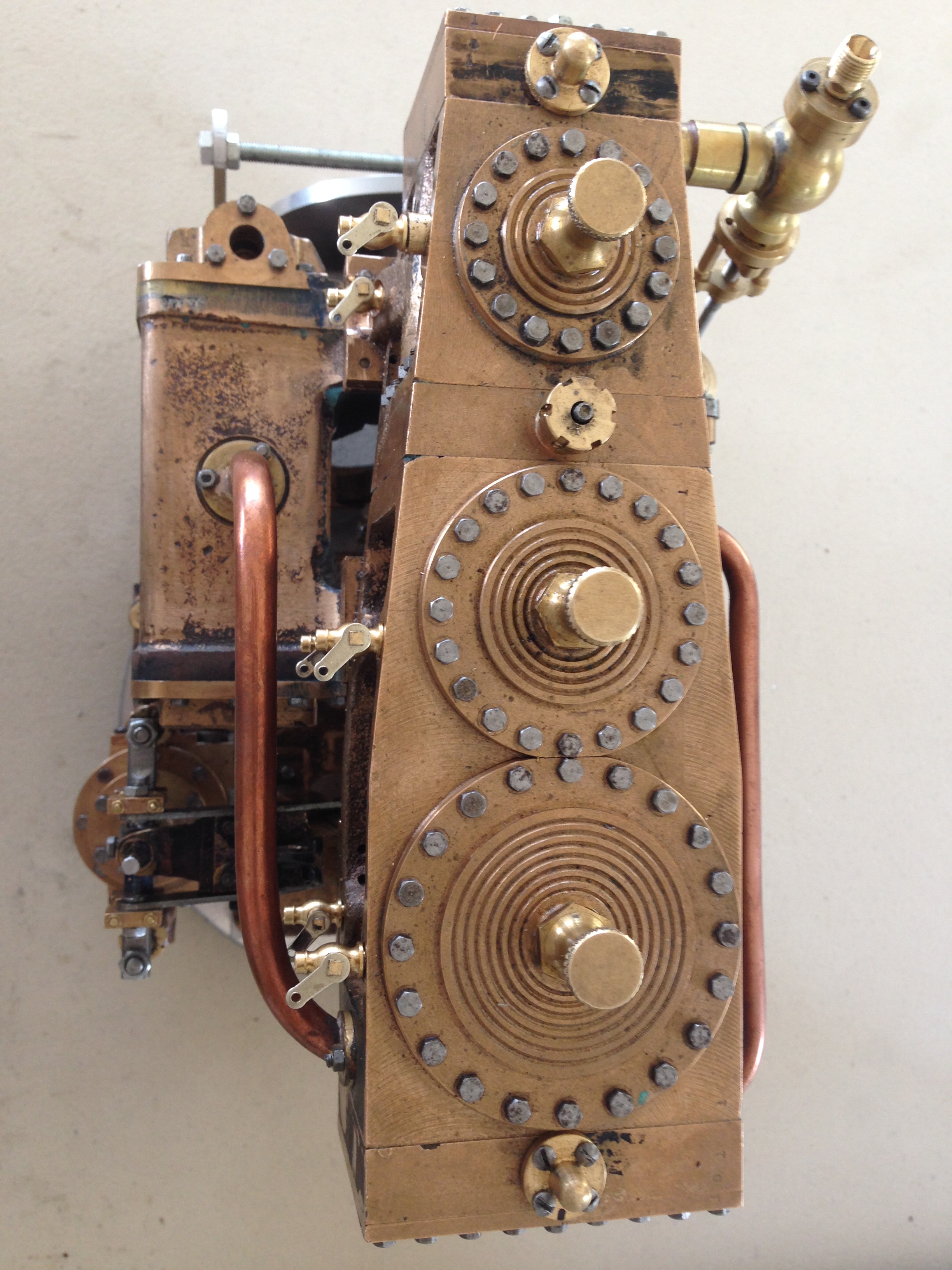
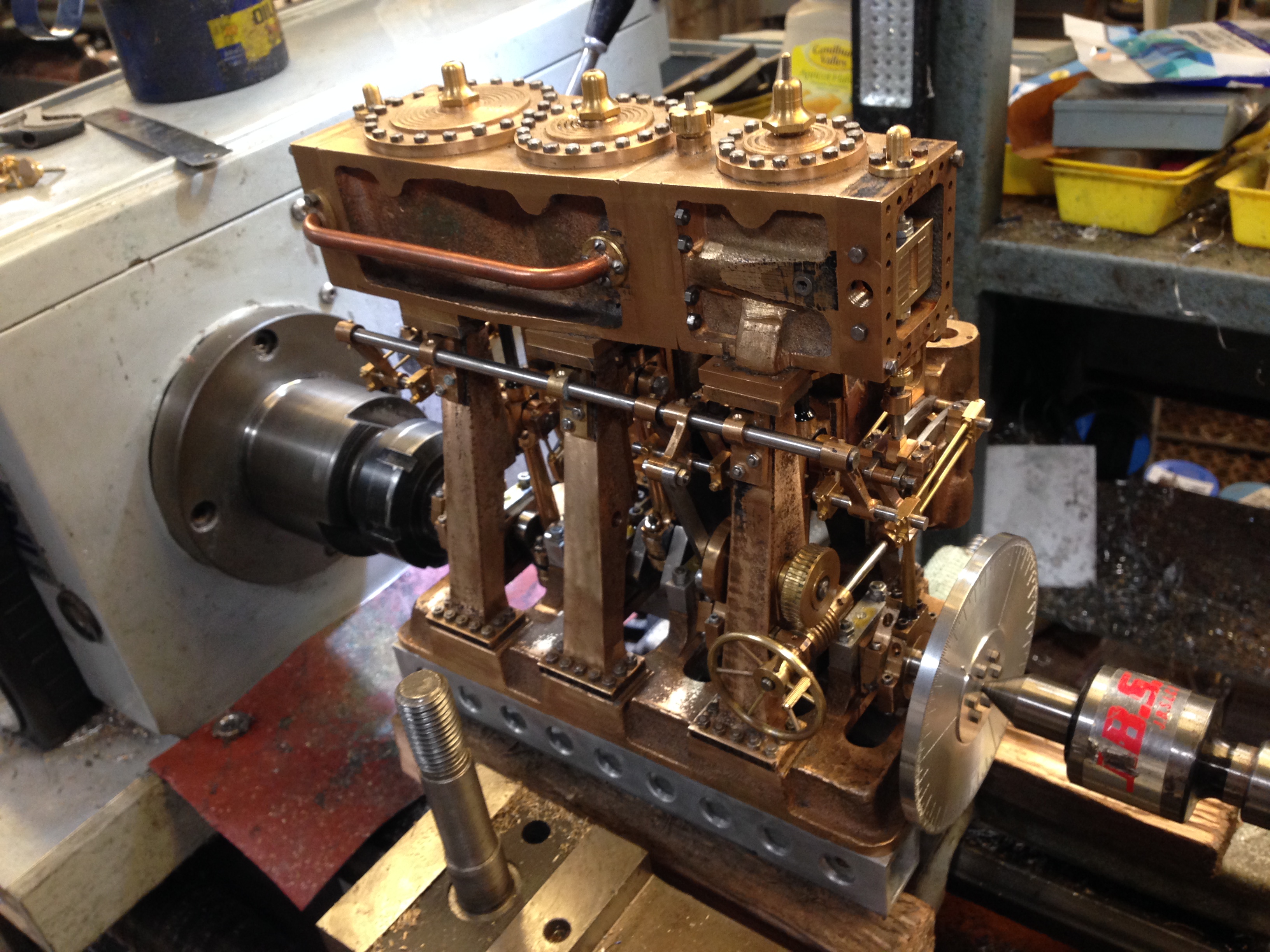
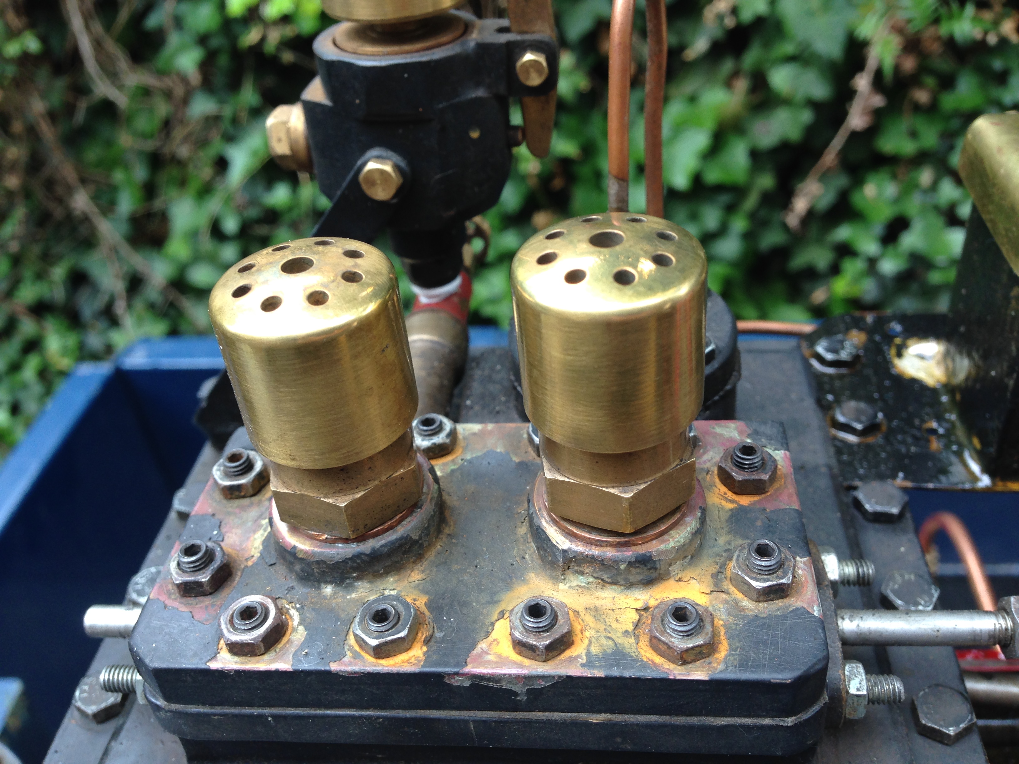
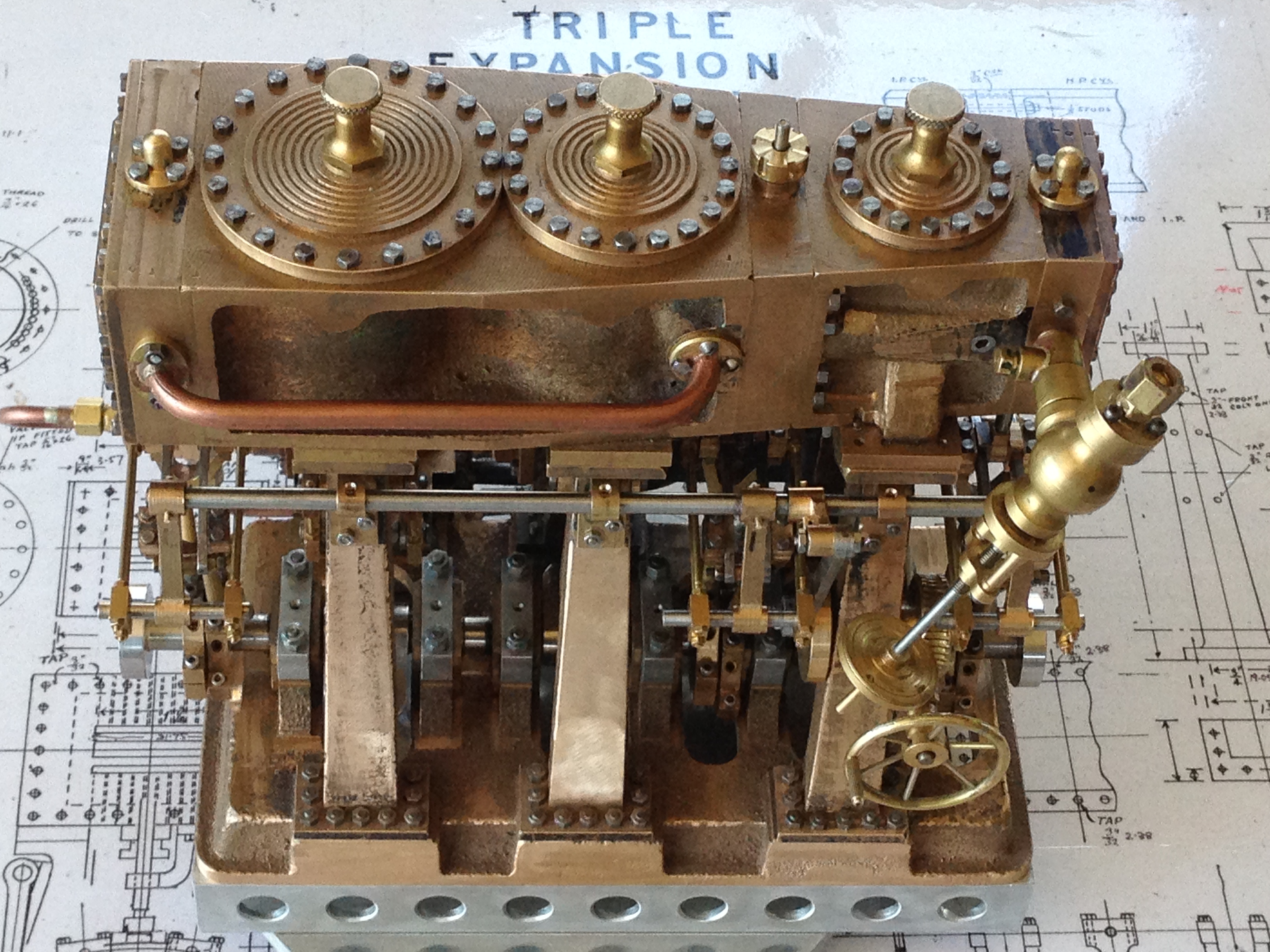
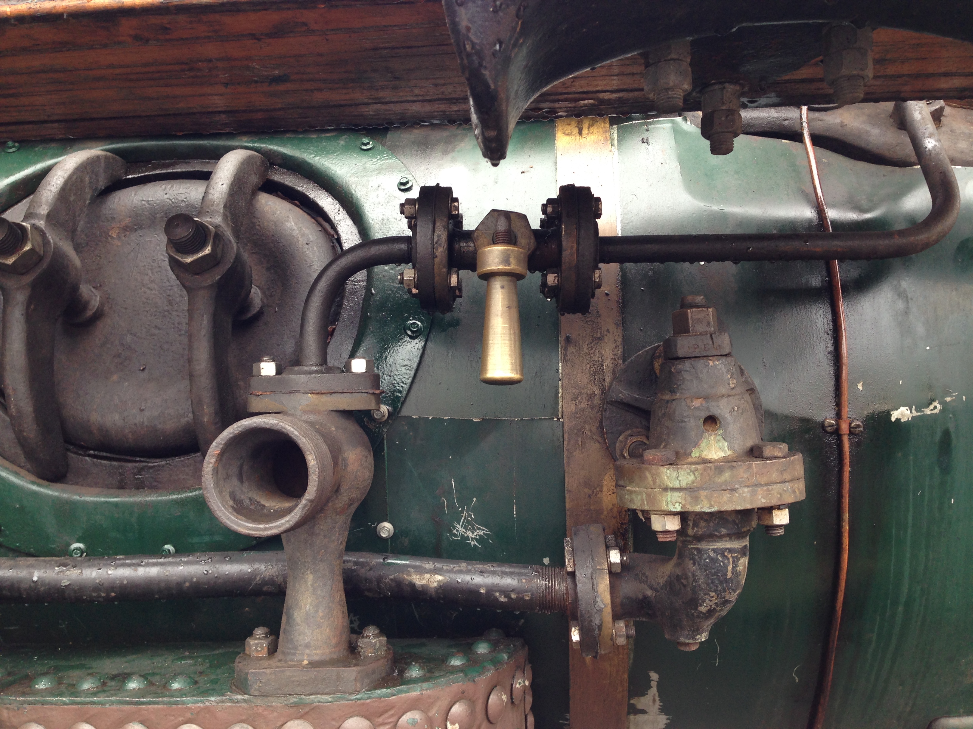
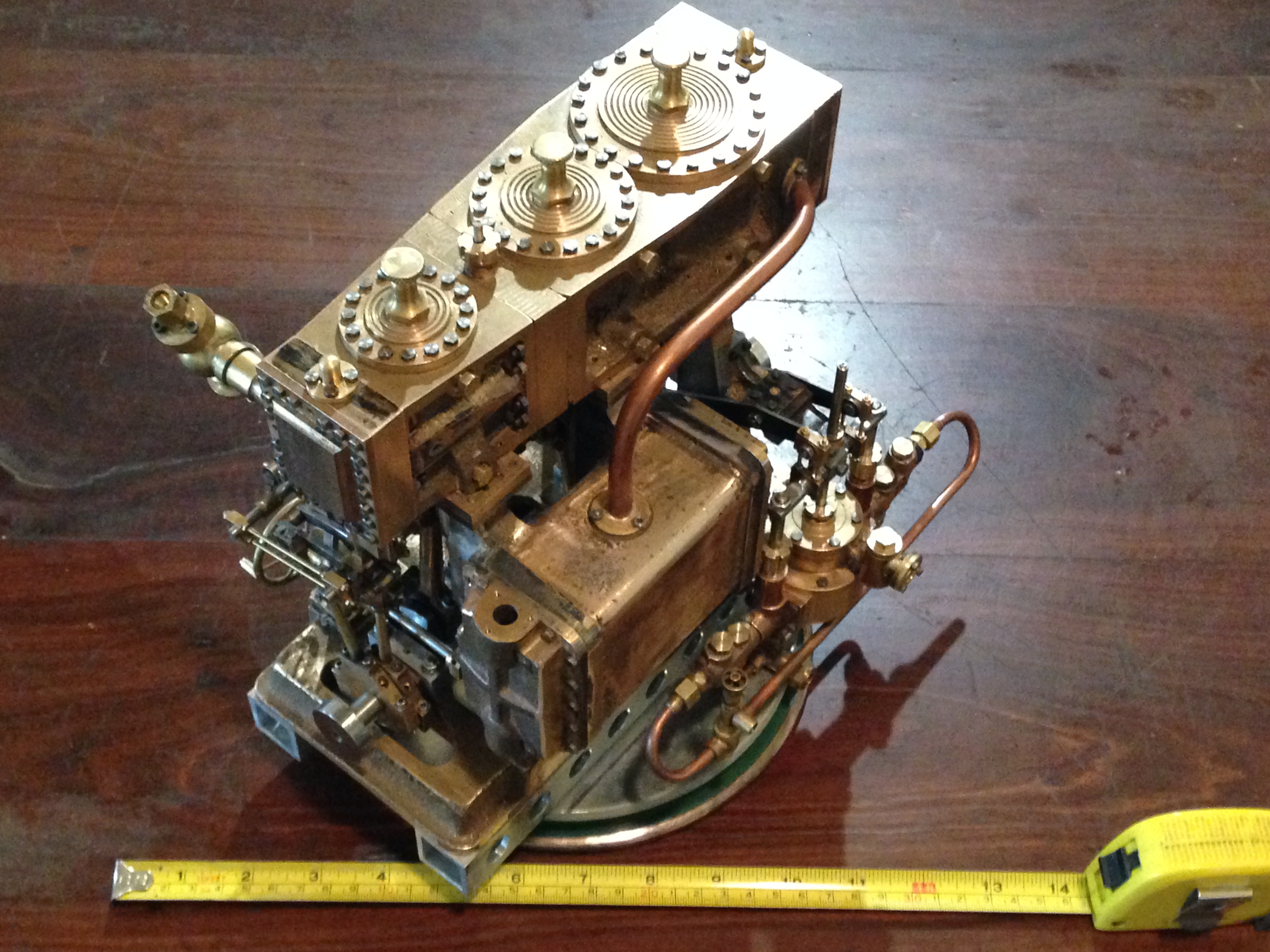
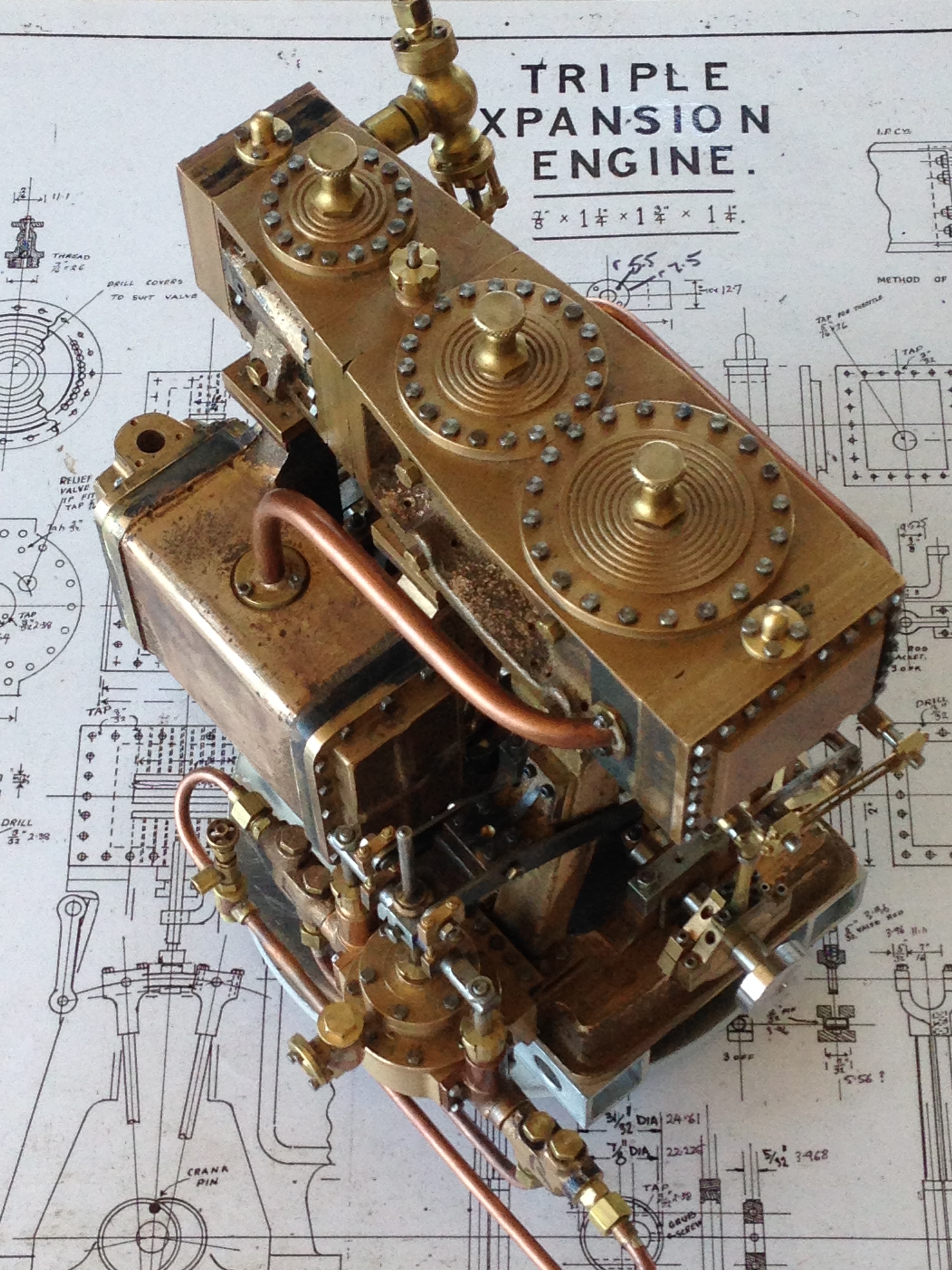
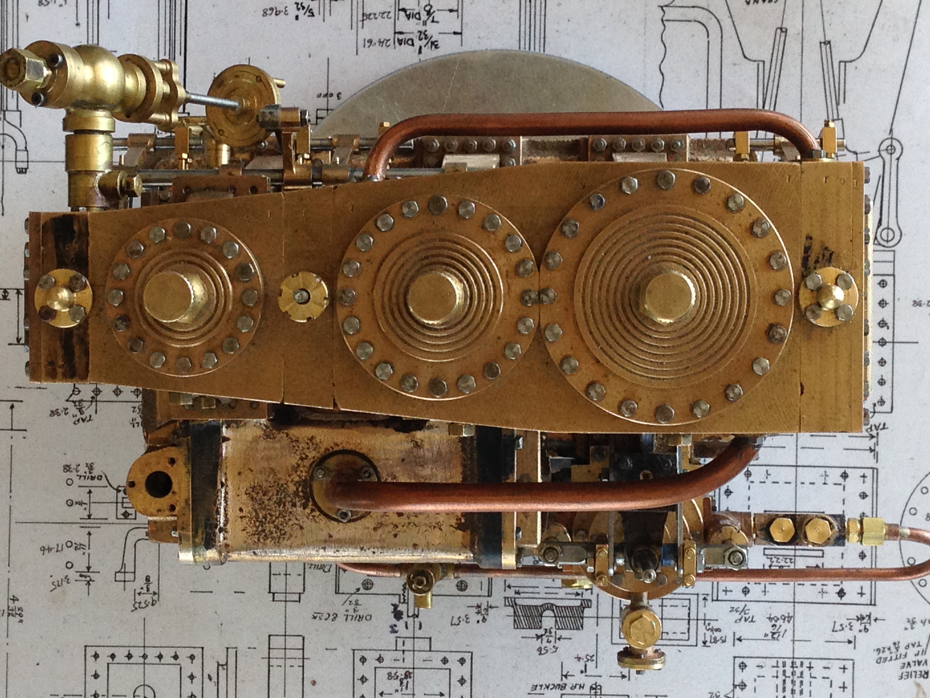
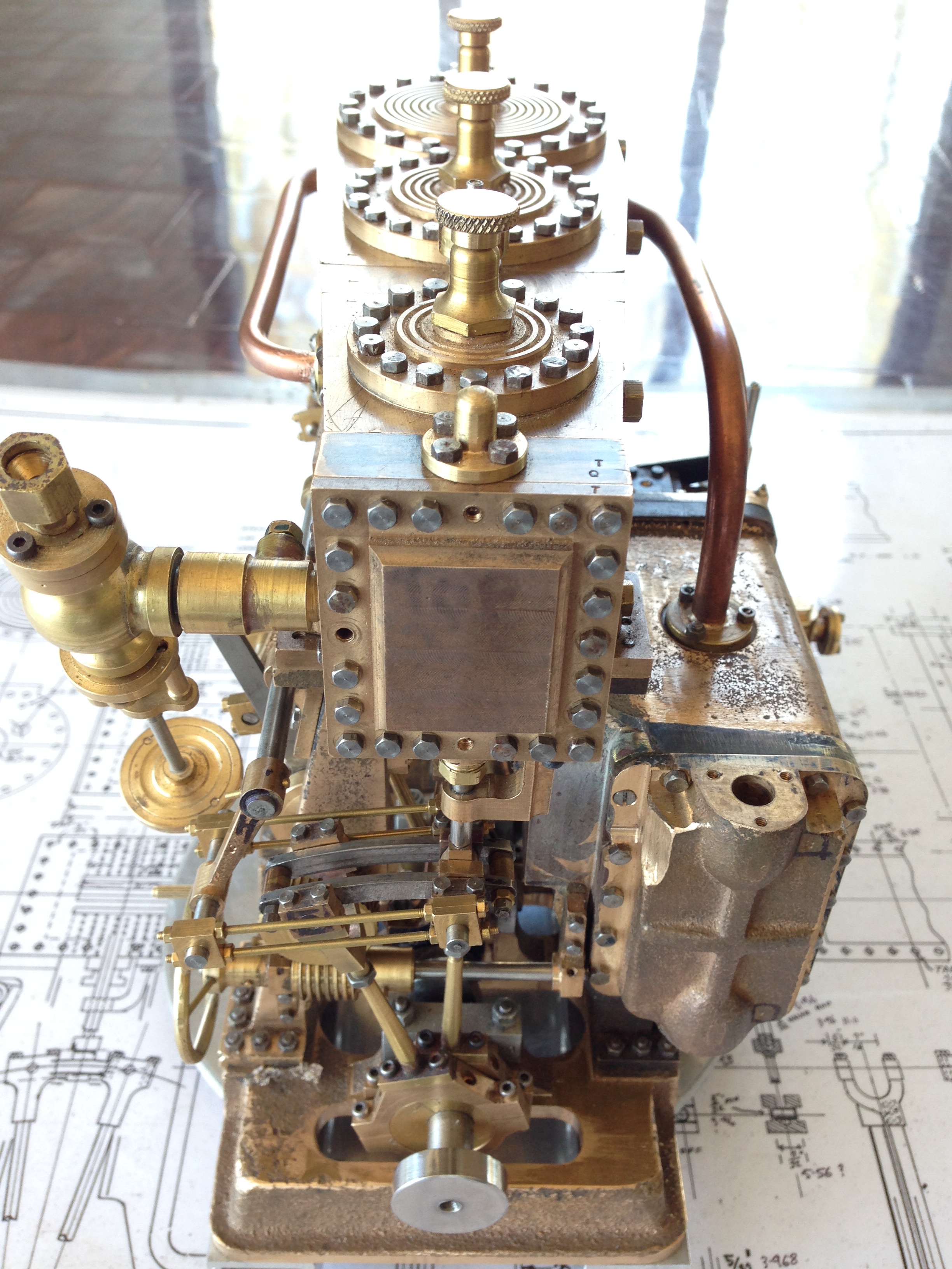
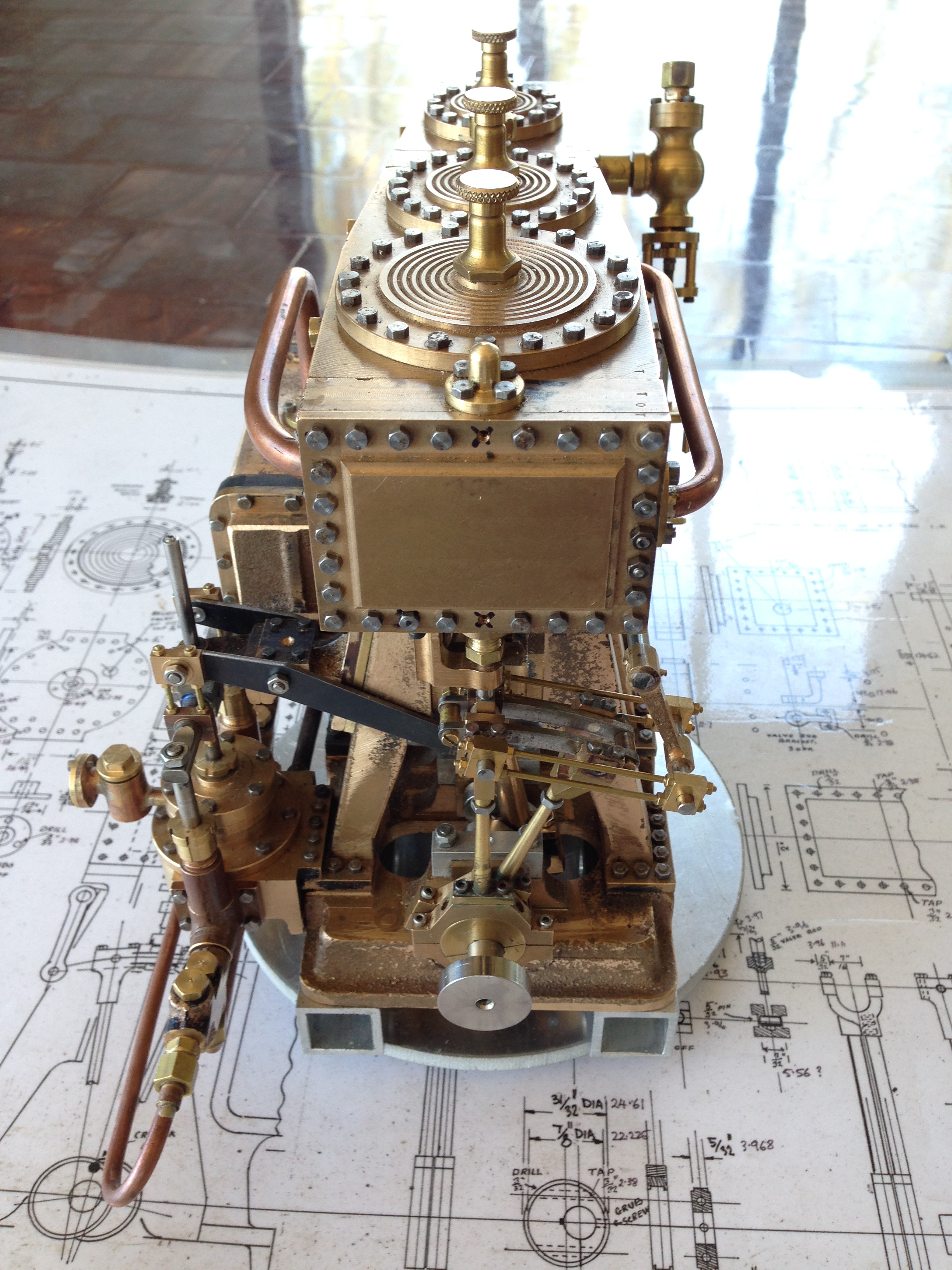
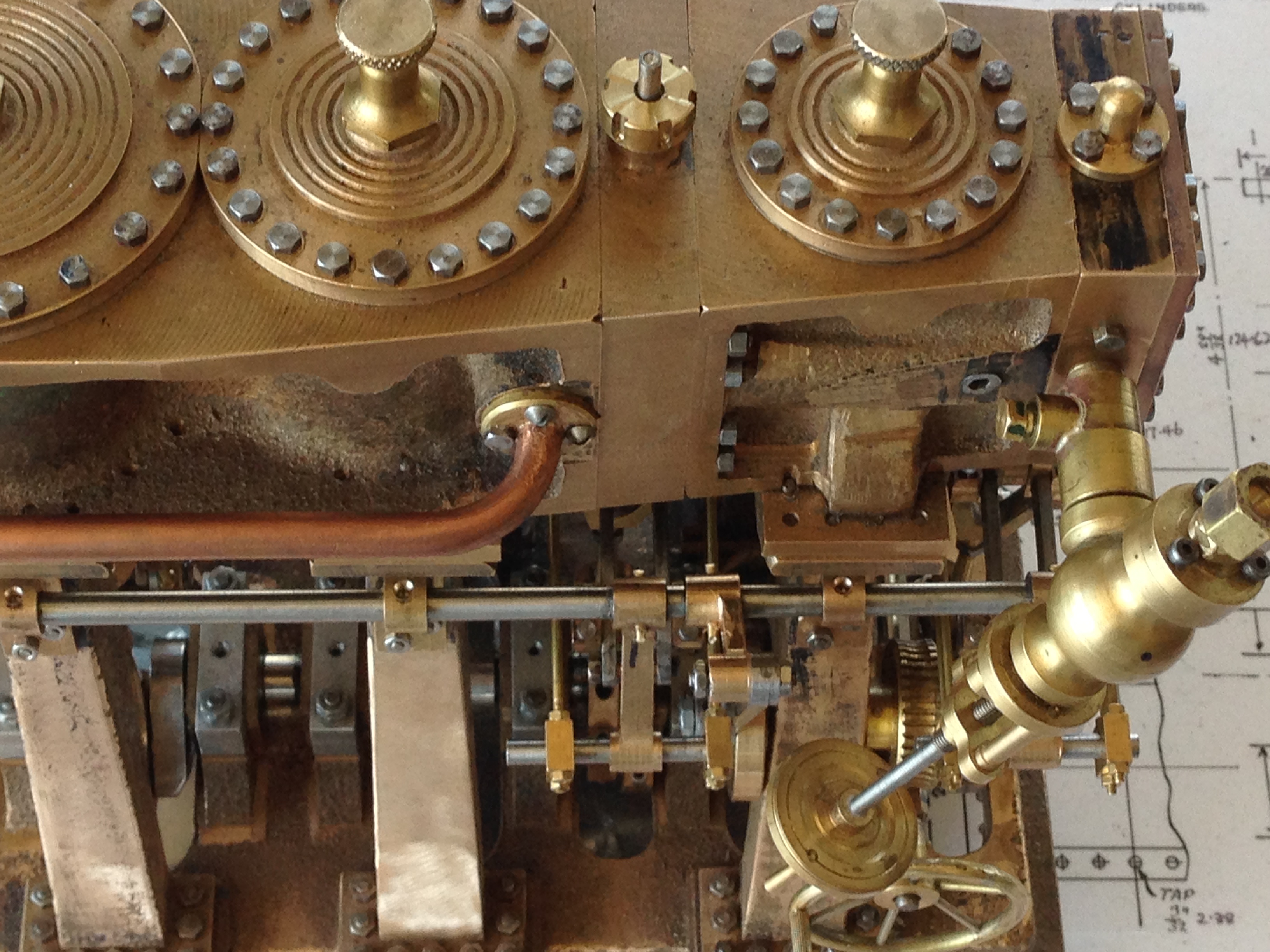
 So I spent the day inserting a lot of square nuts on stainless steel studs, and bolting on some valves. Looks quite interesting? The stainless nuts came from China and were inexpensive. A pity to paint them black.